
 My Inquiry
 My Account


Skyworks Solutions Inc. ATN3580-10
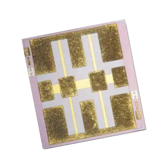
- Part No.:
- ATN3580-10
- Manufacturer:
- Skyworks Solutions Inc.
- Category:
- Attenuators
- Package:
- Module
- Datasheet:
-
 ATN3580-10.pdf
- Description:
- RF ATTENUATOR 10DB MODULE
- Quantity:
- Payment:

- Shipping:

Inventory:3,478
Please send an inquiry. Send us your inquiry, and we will respond immediately.
Product details
Overview
ATN3580-10 from Skyworks Solutions is a fixed thin-film silicon attenuator chip with nominal 10 dB attenuation, ±0.35 dB DC tolerance, ±0.2 dB flatness up to 12 GHz, and minimum 15 dB return loss to 40 GHz. It uses a balanced TEE resistive structure for broadband RF signal conditioning in microwave test equipment and high-frequency transceiver front-ends.
For engineers reviewing the ATN3580-10 datasheet, ATN3580-10 pinout, ATN3580-10 application, or ATN3580-10 equivalent, key selection criteria include its 1 W CW power handling, -55 °C to +150 °C operating temperature range, RoHS-compliant lead-free construction, and guaranteed flatness performance across 0.1–40 GHz.
Technical Context
The ATN3580-10 implements a balanced TEE topology on high-resistivity silicon substrate, enabling broadband impedance matching and stable attenuation over 0.1–40 GHz. Its thin-film resistor fabrication ensures tighter tolerance control and higher thermal stability than thick-film alternatives.
Electrical behavior is characterized at 25 °C with DC-coupled operation; attenuation flatness degrades predictably beyond 12 GHz (±0.30 dB to 26.5 GHz, ±0.50 dB to 40 GHz), while return loss remains ≥15 dB across full bandwidth per Table 3.
Key Specifications
| Parameter | Value and Actual Design Meaning |
|---|---|
| Nominal attenuation | 10 dB - precise signal level reduction without amplification or active control |
| DC tolerance | ±0.35 dB - maximum deviation at DC, defining baseline calibration accuracy |
| Attenuation flatness (0.1–12 GHz) | ±0.2 dB - ensures consistent signal suppression across L/S/C bands |
| Minimum return loss (0.1–40 GHz) | 15 dB - limits VSWR to ≤1.43, reducing mismatch-induced ripple and reflections |
| Power handling | 1 W CW - supports continuous high-power RF testing without thermal derating |
| Operating temperature | -55 °C to +150 °C - enables deployment in aerospace, defense, and under-hood automotive RF modules |
| Package outline | 518-060 - 0.060 × 0.060 inch ceramic chip with defined die-mount land pattern |
Pinout & Package
ATN3580-10 is a two-terminal passive chip device with no polarity or directional pin assignment. It is mounted as a surface-mount die using ribbon bonding or conductive epoxy on a 518-060 outline footprint (0.060″ × 0.060″). No discrete pins exist - RF signal path flows between opposing metallized edges.
| Pin/Terminal | Circuit Role | Design Meaning |
|---|---|---|
| Terminal 1 | RF input / source side | Primary signal entry point; symmetric with Terminal 2 for bidirectional operation |
| Terminal 2 | RF output / load side | Signal exit point after fixed 10 dB loss; identical electrical role to Terminal 1 |
Key Features
| Feature | Design Value |
|---|---|
| Balanced TEE resistive structure | Enables broadband impedance match and flat frequency response without external tuning |
| Thin-film silicon construction | Delivers higher power density and thermal stability vs. thick-film printed attenuators |
| Specified flatness to 40 GHz | Supports millimeter-wave 5G FR2, radar, and satellite comms system validation |
| Rugged die form factor | Withstands mechanical stress during hybrid assembly and wire-bonding processes |
| RoHS-compliant & Green™ | Meets global environmental compliance requirements for industrial and telecom deployments |
Applications
| Test & Measurement Instrumentation | Defense Radar Front-Ends |
|---|---|
Use Scenario: Signal level adjustment in vector network analyzer (VNA) calibration kits and RF power sensor interfaces. IC Role / Device Role / Timing Role: Passive fixed-attenuation element placed between source and DUT to extend dynamic range and prevent receiver saturation. Use Value: ±0.2 dB flatness to 12 GHz ensures traceable amplitude accuracy during S-parameter measurements. | Use Scenario: Inter-stage isolation in T/R module transmit chains operating at X- and Ku-band. IC Role / Device Role / Timing Role: Broadband RF attenuator integrated into MMIC-based transmit paths to suppress LO leakage and improve spectral purity. Use Value: 15 dB return loss to 40 GHz minimizes standing waves that degrade PA efficiency and phase noise. |
| 5G mmWave Base Station Radios | Satellite Communication Transceivers |
Use Scenario: Gain control and signal conditioning in phased-array antenna beamformer IC interconnects. IC Role / Device Role / Timing Role: Fixed-loss pad used between GaN driver stages and antenna switch modules to manage peak power distribution. Use Value: 1 W CW rating allows uninterrupted operation during burst-mode 5G NR transmission cycles. | Use Scenario: Input protection and level setting in LNB downconverters and uplink modulator stages. IC Role / Device Role / Timing Role: DC-coupled attenuator placed before mixer inputs to prevent compression and intermodulation distortion. Use Value: -55 °C to +150 °C operating range supports deployment in thermally uncontrolled LEO satellite payloads. |
Equivalent & Alternatives
The following parts are listed as comparable options for similar fixed-attenuation applications.
| Alternative Part | Technical Difference | Application Difference | Selection Advice |
|---|---|---|---|
| Mini-Circuits VAT-10W+ | Surface-mount ceramic package; 10 dB ±0.4 dB tolerance; 0.01–20 GHz bandwidth; 2 W power rating | Limited to 20 GHz - unsuitable for Ka-band or 40 GHz test systems | Select when higher power margin is required below 20 GHz and wider flatness tolerance is acceptable |
| Qorvo QPA1009 | Monolithic GaAs MMIC attenuator; 10 dB ±0.5 dB; 0.1–40 GHz; integrated bias circuitry; 0.5 W rating | Active bias requirement adds design complexity; lower power handling than ATN3580-10 | Select only if DC blocking or integrated control interface is needed - otherwise ATN3580-10 offers superior simplicity and reliability |
Compared with VAT-10W+ and QPA1009, the ATN3580-10 delivers wider bandwidth (to 40 GHz), tighter flatness (±0.2 dB to 12 GHz), and higher CW power handling (1 W) in a passive, DC-coupled, zero-bias solution ideal for high-frequency instrumentation and defense RF subsystems.
Availability
ATN3580-10 is available at Aetrix Electronics and suitable for RF test equipment, defense radar modules, 5G mmWave radios, and satellite communication transceivers requiring stable component supply across extended temperature ranges and multi-decade product lifecycles.
Supply support for ATN3580-10 includes scheduled delivery planning, volume procurement assistance, BOM continuity management, traceable sourcing, and lifecycle availability coordination for OEM customers, industrial embedded developers, connected-device designers, and electronics production programs.
Manufacturer
Skyworks Solutions is a global semiconductor company specializing in analog and mixed-signal connectivity solutions for wireless, broadband, automotive, and industrial markets.
The ATN3580 series belongs to Skyworks' high-frequency passive components product line, engineered specifically for precision RF signal conditioning in microwave and millimeter-wave systems where broadband flatness, thermal robustness, and repeatability are critical.
FAQ
What is the DC attenuation tolerance of the ATN3580-10?
The ATN3580-10 has a DC attenuation tolerance of ±0.35 dB as specified in Table 2 of the Skyworks datasheet. This tolerance defines the maximum allowable deviation from the nominal 10 dB value at DC and forms the baseline for all frequency-dependent flatness specifications. The ATN3580-10 maintains this tight tolerance across its full operating temperature range of -55 °C to +150 °C.
Does the ATN3580-10 require DC blocking capacitors?
No, the ATN3580-10 is a DC-coupled passive attenuator and does not require DC blocking capacitors. Its balanced TEE structure operates from DC to 40 GHz, making it suitable for applications involving baseband signals, pulse modulation, or low-frequency RF where DC continuity is essential. The ATN3580-10 is explicitly specified for attenuation at DC per the Skyworks datasheet description.
What is the recommended mounting method for the ATN3580-10?
Skyworks recommends die mounting the ATN3580-10 using conductive epoxy or eutectic solder onto a 518-060 land pattern, followed by ribbon bonding to both terminals. Figure 4 of the datasheet provides the suggested die mount and ribbon attachment drawing for ≥6 dB attenuators like the ATN3580-10. Mechanical clamping or flip-chip bonding is not supported. The ATN3580-10 must be handled per ESD Class 2 (HBM) precautions.
Is the ATN3580-10 suitable for space-level applications?
The ATN3580-10 is not certified for space-level use, though its -55 °C to +150 °C operating temperature range and rugged thin-film silicon construction support demanding terrestrial and airborne environments. It lacks radiation hardness qualification, MIL-PRF-19500 screening, or QML-V certification. For space applications, users must perform independent radiation testing and lot acceptance per their program requirements. The ATN3580-10 itself is rated for commercial and industrial use only.
How does the ATN3580-10 compare to thick-film attenuators in power handling?
The ATN3580-10 achieves 1 W CW power handling due to its thin-film silicon construction, which provides superior thermal conductivity and resistor stability compared to traditional thick-film printed attenuators. Thick-film variants typically max out at 0.25–0.5 W before significant drift or failure occurs. This 2×–4× improvement enables the ATN3580-10 to sustain continuous operation in high-power test fixtures and radar transmitter stages where the ATN3580-10's thermal performance is critical.
ATN3580-10 Specifications
- Product attributes
- Attribute value
- Manufacturer:
- Skyworks Solutions Inc.
- Package/Case:
- Module
- Series:
- ATN3580
- Packaging:
- Tray
- Product Status:
- Active
- Attenuation Value:
- 10dB
- Frequency Range:
- 100 MHz ~ 40 GHz
- Power (Watts):
- 1W
- Impedance:
- -
- Grade:
- -
- Qualification:
- -
ATN3580-10 FAQ
1.How can I place an order for ATN3580-10 through Aetrix?
Please submit a Request for Quotation (RFQ) for ATN3580-10 on Aetrix. Our sales agent will provide a competitive quotation and guide you through the order confirmation once you accept the terms.
2.Are the price and stock information for ATN3580-10 reliable?
The price and inventory of ATN3580-10 are updated periodically and may fluctuate due to market conditions. Stock and pricing data are typically refreshed every 24 hours. Quotation validity for ATN3580-10 is usually 5 days.
3.What payment methods are accepted for ATN3580-10?
We accept Wire Transfer, PayPal, Credit Card, Western Union, MoneyGram, and Escrow for ATN3580-10 transactions.
Note: Certain payment methods may incur a processing fee.
4.How is shipping managed for ATN3580-10?
ATN3580-10 orders can be shipped via leading logistics carriers, including DHL, UPS, FedEx, TNT, or Registered Mail.
Once your ATN3580-10 order is processed, you will receive an email with the shipment details and tracking number.
Note: Tracking information may take up to 24 hours to appear. Express delivery typically takes 3–5 business days.
5.How can I obtain technical support or documentation for ATN3580-10?
For technical support, including ATN3580-10 datasheets, pinout diagrams, or application guidance, please contact our engineering support team. They can provide detailed documentation and assistance for your ATN3580-10 requirements.
6.How does Aetrix verify that ATN3580-10 is sourced from the original manufacturer or authorized distributors?
All ATN3580-10 products on Aetrix are procured from qualified distributors and authorized channels. Our dedicated quality assurance team conducts strict verification, including traceability checks and, if necessary, third-party testing. This ensures that ATN3580-10 meets industry standards.
7.What is the process for return or replacement of ATN3580-10?
All ATN3580-10 units undergo pre-shipment inspection (PSI). If there is an issue with ATN3580-10, returns or replacements are accepted under the following conditions:
1.Quantity discrepancies, incorrect items, or visible external defects (such as breakage or corrosion), acknowledged by Aetrix.
2.The issue is reported within 90 days of delivery.
3.The ATN3580-10 part is unused and in its original packaging.
Return procedure for ATN3580-10:
1.Submit a request within 90 days.
2.Obtain a Return Material Authorization (RMA) from Aetrix.
ATN3580-10 Tags

-
PAT0510S-C-3DB-T10
Susumu
-
PAT0510S-C-10DB-T10
Susumu
-
PAT0510S-C-2DB-T10
Susumu
-
PAT1220-C-10DB-T5
Susumu
-
PAT1220-C-6DB-T5
Susumu
-
PAT1220-C-0DB-T5
Susumu
-
PAT1220-C-3DB-T5
Susumu
-
PAT1220-C-5DB-T5
Susumu
-
PAT1220-C-8DB-T5
Susumu
-
MAADSS0008TR-3000
MACOM Technology Solutions
-
MAATSS0018TR-3000
MACOM Technology Solutions
-
PE43205B-Z
pSemi
Tech Hub

Counterfeit components can hide behind convincing markings and passing basic function tests. This engineering reference covers source traceability, external inspection, X-ray, XRF, electrical testing, …

A practical engineering and sourcing framework covering lifecycle verification, lifetime-buy calculations, replacement qualification, supplier checks and counterfeit-risk controls.

TTL and CMOS logic families differ in thresholds, loading, output drive, power and timing. This engineering guide compares 74HC and 74HCT, calculates noise margins and checks 3.3 V/5 V compatibility.

A practical engineering guide to 3.3V and 5V logic compatibility, input thresholds, resistor dividers, translator ICs, MOSFET level shifting, I2C pull-ups, timing limits and power-sequencing risks.

The 74HC595 uses push-pull logic outputs, while the TPIC6B595 uses 50 V open-drain DMOS sinks for higher-power loads. This guide compares timing, current limits, 3.3 V interfacing, load wiring, thermal…

The 74HC595 converts serial data into eight stable parallel outputs. This guide covers pin functions, shift and storage timing, OE and MR behavior, drive-current limits, cascading, voltage compatibilit…

A technical comparison of level-sensitive latches and edge-triggered flip-flops, covering timing windows, setup and hold limits, master–slave operation, time borrowing, race-through, HDL inference and…

A D latch stores one bit while Enable controls when data can pass. This reference covers gate-level operation, truth tables, transparency, setup and hold timing, LE versus OE, common ICs and practical …

An SR latch stores one bit through cross-coupled feedback. This engineering reference covers NOR and NAND implementations, truth tables, forbidden-state recovery, gated operation, switch debouncing, fa…

Latch circuits retain one bit through feedback. This technical reference covers SR and D latches, truth tables, transparency, timing limits, latch-versus-flip-flop behavior, applications and common log…


