
 My Inquiry
 My Account


Microchip Technology ATR2406-PNQW
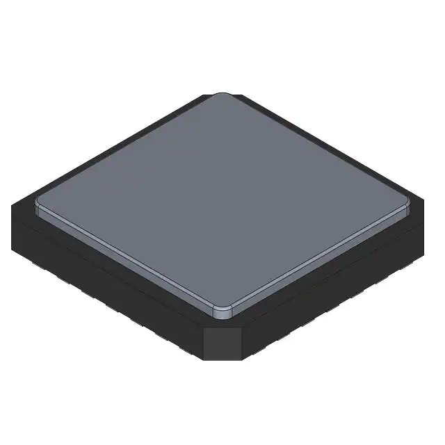
- Part No.:
- ATR2406-PNQW
- Manufacturer:
- Microchip Technology
- Category:
- RF Transceiver ICs
- Package:
- 32-VFQFN Exposed Pad
- Datasheet:
-
 ATR2406-PNQW.pdf
- Description:
- IC RF TXRX ISM>1GHZ 32QFN
- Quantity:
- Payment:

- Shipping:

Inventory:1,800
Please send an inquiry. Send us your inquiry, and we will respond immediately.
Product details
Overview
ATR2406-PNQW from Microchip Technology (formerly Atmel) is a fully integrated low-IF 2.4 GHz ISM band transceiver in QFN32 package, featuring –93 dBm sensitivity, +4 dBm output power, 95-channel frequency hopping, and on-chip clock recovery for 1152 kbps data rates. It serves as the RF front-end in wireless game controllers and telemetry systems requiring FCC/ETSI compliance.
For engineers reviewing the ATR2406-PNQW datasheet, ATR2406-PNQW pinout, ATR2406-PNQW application, or ATR2406-PNQW equivalent, key selection considerations include its integrated Gaussian filter (±400 kHz deviation), 3-wire SPI interface timing (10 MHz max), auxiliary voltage regulator (3.2–4.6 V input), and differential RX input impedance (170 Ω).
Technical Context
The ATR2406-PNQW implements a low-IF architecture with 864 kHz IF frequency, image-rejection mixer, integrated VCO (2400–2483 MHz), and programmable PLL using reference frequencies of 10.368 MHz or 13.824 MHz. Its synthesizer supports 95 discrete channels via main counter (SMC = 86–89) and swallow counter (SSC = 0–31) configuration.
Transmit path includes an integrated Gaussian filter, TX preamplifier, and ramp-signal generator (RAMP_OUT) for external PA control; receive path integrates LNA, limiting IF amplifier, RSSI, and FM demodulator with internal clock recovery - active only at 1152 kbps and outputting recovered clock on pin 6 (RX-CLOCK).
Key Specifications
| Parameter | Value and Actual Design Meaning |
|---|---|
| Operating Band | 2.400–2.483 GHz ISM band; supports ETSI EN 300 328 and FCC Part 15 compliance |
| RX Sensitivity | –93 dBm @ BER ≤10⁻³, 1152 kbps; enables reliable link budget in low-power remote applications |
| TX Output Power | +4 dBm typical at TX_OUT; sufficient to drive external PA via RAMP_OUT-controlled bias |
| Data Rates | 72 / 144 / 288 / 576 / 1152 kbps GFSK; clock recovery enabled only at 1152 kbps |
| Supply Range | 2.9–3.6 V (main); auxiliary regulator accepts 3.2–4.6 V for VREG/VREG_VCO generation |
| Channel Count | 95 fixed-frequency channels; every second channel usable without spectral overlap due to ±400 kHz deviation |
| Interface | 3-wire SPI (CLOCK/DATA/ENABLE); 10 MHz max clock, 3 µs register programming time |
Pinout & Package
Package: QFN32 (5 mm × 5 mm × 0.9 mm), lead-free, RoHS-compliant, exposed paddle grounded.
| Pin/Terminal | Circuit Role | Design Meaning |
|---|---|---|
| PU_REG (Pin 1) | Auxiliary regulator enable | Activates on-chip AUX regulator and VCO voltage regulator; must be high for VREG/VREG_VCO operation |
| REF_CLK (Pin 2) | Reference clock input | Accepts 10.368 MHz or 13.824 MHz sine wave (500–1000 mVpp); sets PLL comparison frequency at 1.728 MHz |
| RSSI (Pin 3) | Received signal strength indicator | Analog voltage output (0.1–2.1 V) monotonic over –96 to –36 dBm input range |
| VS_IFD / VS_IFA (Pins 4, 5) | Digital/analog IF supply | Separate 2.9–3.6 V supplies for digital baseband and analog IF circuits to minimize noise coupling |
| RX-CLOCK (Pin 6) | Recovered clock output | Falling edge samples RX_DATA; available only when clock recovery is enabled (1152 kbps mode) |
| TX_ON (Pin 25) | Transmit activation | Starts internal ramp generator and enables TX path; triggers RAMP_OUT voltage transition |
| RX_ON (Pin 24) | Receive activation | Enables DEMOD, IF AMP, and IR_MIXER; must be asserted before RX slot |
| RAMP_OUT (Pin 21) | External PA ramp control | Programmable 0.7–1.9 V output (via D12/D13 bits); controls PA bias slew rate to meet spurious emission limits |
Key Features
| Feature | Design Value |
|---|---|
| Integrated clock recovery | Eliminates need for external clock source at receiver; recovered clock on Pin 6 synchronizes MCU sampling |
| Gaussian filter with GFCS tuning | D11–D9 bits adjust modulation deviation (60–130% of nominal ±400 kHz) to compensate production tolerances |
| Multi-channel frequency hopping | 95 channels with programmable SMC/SSC registers; supports ETSI-compliant FHSS for interference resilience |
| Low-power operation modes | Power-down current <1 µA; burst-mode RX/TX currents of 625 µA / 500 µA at 10 kbps duty cycle |
| On-chip auxiliary regulator | Generates stable 3.0 V (VREG) and 2.7 V (VREG_VCO) from 3.2–4.6 V battery input, reducing external BOM |
Applications
| Wireless Game Controllers | Telemetry Systems |
|---|---|
Use Scenario: Low-latency bidirectional communication between handheld controller and console/base station using frequency-hopping spread spectrum. IC Role / Device Role / Timing Role: Full-duplex transceiver handling TX bursts (210 µs at 1152 kbps) and RX slots with 200 µs channel switch time. Use Value: Integrated clock recovery eliminates external clock distribution; ±400 kHz deviation ensures robust GFSK demodulation under RF interference. | Use Scenario: Battery-powered sensor node transmitting periodic health/status data to gateway over unlicensed 2.4 GHz band. IC Role / Device Role / Timing Role: Burst-mode transceiver operating at 144 kbps with 0.9% duty cycle; leverages power-down mode (<1 µA) between transmissions. Use Value: Ultra-low RX/TX peak currents (57/42 mA) and integrated ramp generator extend battery life beyond 1.4 years on 100 mAh cell. |
| Wireless Audio/Video Links | Electronic Point-of-Sale (POS) |
Use Scenario: Short-range uncompressed audio streaming between headset and media player using adaptive channel selection. IC Role / Device Role / Timing Role: High-sensitivity (–93 dBm) receiver with 32 dBc intermodulation rejection enables clean reception amid co-located 2.4 GHz devices. Use Value: Differential RX inputs (170 Ω) and integrated image-rejection mixer suppress adjacent-channel interference in dense RF environments. | Use Scenario: Cordless barcode scanner communicating with POS terminal via secure, low-jitter packet transmission. IC Role / Device Role / Timing Role: Transceiver implementing deterministic 200 µs TX→RX turnaround and 3 µs register programming for rapid command-response cycles. Use Value: On-chip Gaussian filter and programmable GFCS ensure consistent modulation accuracy across production units, meeting FCC spectral mask requirements. |
Equivalent & Alternatives
The following parts are listed as comparable options for similar 2.4 GHz ISM transceiver applications.
| Alternative Part | Technical Difference | Application Difference | Selection Advice |
|---|---|---|---|
| CC2530F256RHAT | Integrated 8051 MCU + 2.4 GHz IEEE 802.15.4 PHY/MAC; no clock recovery; lower TX power (+0 dBm) | Designed for Zigbee/6LoWPAN mesh networks; requires full protocol stack implementation | Select when system-level integration (MCU + RF) and standards-based networking outweigh raw sensitivity and clock recovery needs. |
| nRF24L01+ | Proprietary 2.4 GHz transceiver; +4 dBm TX power; no integrated LNA (–80 dBm sensitivity); 32-pin QFN same footprint | Optimized for ultra-low-cost consumer remotes; lacks frequency hopping support and regulatory compliance features | Select for cost-sensitive, non-certified applications where link budget margin is sufficient and FCC/ETSI certification is not required. |
Compared with CC2530F256RHAT and nRF24L01+, the ATR2406-PNQW delivers superior sensitivity (–93 dBm vs. –80 dBm) and built-in clock recovery-critical for low-jitter synchronous data recovery-but requires external MCU and more complex register configuration for FHSS.
Availability
ATR2406-PNQW is available at Aetrix Electronics and suitable for wireless game controllers, telemetry nodes, wireless audio links, and electronic point-of-sale terminals requiring stable component supply and FCC/ETSI regulatory compliance.
Supply support for ATR2406-PNQW includes scheduled delivery planning, volume procurement assistance, BOM continuity management, traceable sourcing, and lifecycle availability coordination for OEM customers, industrial embedded developers, connected-device designers, and electronics production programs.
Manufacturer
Microchip Technology acquired Atmel in 2016 and maintains its legacy RF IC portfolio, emphasizing high-integration, low-power wireless solutions for industrial and consumer markets.
The ATR2406-PNQW belongs to Atmel's legacy ISM transceiver product line, designed specifically for battery-operated, short-range, frequency-hopping GFSK systems in toys, controllers, and telemetry where regulatory compliance and link robustness are critical.
FAQ
What is the maximum data rate supported by the ATR2406-PNQW with on-chip clock recovery enabled?
The ATR2406-PNQW supports clock recovery exclusively at 1152 kbps. At this rate, the recovered clock is output on pin 6 (RX-CLOCK), with the falling edge used to sample RX_DATA. Lower data rates (72–576 kbps) require external clocking and disable the clock recovery function entirely. This design ensures precise timing alignment only at the highest supported rate.
How does the ATR2406-PNQW achieve FCC/ETSI compliance without external filtering components?
The ATR2406-PNQW meets FCC Part 15 and ETSI EN 300 328 requirements through integrated harmonic suppression (–41.2 dBm), spurious emission limits (–57 dBm across 30 MHz–12.75 GHz), and controlled ramping via RAMP_OUT. Its Gaussian filter, programmable GFCS bits, and internal TX preamplifier eliminate need for external SAW filters or baluns in certified reference designs like ATR2406-DEV-BOARD.
Can the ATR2406-PNQW operate without the auxiliary voltage regulator (AUX) circuit?
Yes, the ATR2406-PNQW supports two supply configurations: with AUX regulator (3.2–4.6 V input to VS_REG, generating 3.0 V VREG and 2.7 V VREG_VCO) or without (2.9–3.6 V applied directly to VS_TRX/VS_IFD/VS_IFA). When bypassing AUX, PU_REG must be tied low and pin 7 (IC) connected to VS to enable internal F-antenna routing per datasheet Section 10.1.
What is the function of pins 22, 23, and 7 labeled "IC" in the ATR2406-PNQW pinout?
Pins 22 and 23 are internally connected and must remain unconnected on PCB. Pin 7 is also internally connected but serves a dual purpose: when AUX regulator is disabled, it must be tied to VS_IFD or VS_IFA to route signals to the integrated F-antenna; when AUX is enabled, it is left floating. All three pins are test points internal to the die and carry no user-accessible signal.
How many channels can be simultaneously active in frequency-hopping mode on the ATR2406-PNQW?
The ATR2406-PNQW supports 95 discrete channels in the 2.400–2.483 GHz band, but only one channel is active at any instant. Frequency hopping is sequential: the host MCU reprograms PLL registers (SMC/SSC) between slots to switch channels, with 200 µs channel switch time. The "multi-channel operation" feature refers to rapid reconfiguration-not concurrent multi-channel reception or transmission.
ATR2406-PNQW Specifications
- Product attributes
- Attribute value
- Manufacturer:
- Microchip Technology
- Series:
- -
- Package/Case:
- 32-VFQFN Exposed Pad
- Packaging:
- Tape & Reel (TR)
- Product Status:
- Obsolete
- Programmable:
- Not Verified
- Type:
- TxRx Only
- RF Family/Standard:
- General ISM > 1GHz
- Protocol:
- -
- Modulation:
- GFSK
- Frequency:
- 2.4GHz
- Data Rate (Max):
- 1.125Mbps
- Power - Output:
- 4dBm
- Sensitivity:
- -93dBm
- Memory Size:
- -
- Serial Interfaces:
- SPI
- GPIO:
- -
- Voltage - Supply:
- 2.9V ~ 3.6V
- Current - Receiving:
- 57mA
- Current - Transmitting:
- 42mA
- Operating Temperature:
- -10°C ~ 60°C
- Grade:
- -
- Qualification:
- -
- Supplier Device Package:
- 32-QFN (5x5)
ATR2406-PNQW FAQ
1.How can I place an order for ATR2406-PNQW through Aetrix?
Please submit a Request for Quotation (RFQ) for ATR2406-PNQW on Aetrix. Our sales agent will provide a competitive quotation and guide you through the order confirmation once you accept the terms.
2.Are the price and stock information for ATR2406-PNQW reliable?
The price and inventory of ATR2406-PNQW are updated periodically and may fluctuate due to market conditions. Stock and pricing data are typically refreshed every 24 hours. Quotation validity for ATR2406-PNQW is usually 5 days.
3.What payment methods are accepted for ATR2406-PNQW?
We accept Wire Transfer, PayPal, Credit Card, Western Union, MoneyGram, and Escrow for ATR2406-PNQW transactions.
Note: Certain payment methods may incur a processing fee.
4.How is shipping managed for ATR2406-PNQW?
ATR2406-PNQW orders can be shipped via leading logistics carriers, including DHL, UPS, FedEx, TNT, or Registered Mail.
Once your ATR2406-PNQW order is processed, you will receive an email with the shipment details and tracking number.
Note: Tracking information may take up to 24 hours to appear. Express delivery typically takes 3–5 business days.
5.How can I obtain technical support or documentation for ATR2406-PNQW?
For technical support, including ATR2406-PNQW datasheets, pinout diagrams, or application guidance, please contact our engineering support team. They can provide detailed documentation and assistance for your ATR2406-PNQW requirements.
6.How does Aetrix verify that ATR2406-PNQW is sourced from the original manufacturer or authorized distributors?
All ATR2406-PNQW products on Aetrix are procured from qualified distributors and authorized channels. Our dedicated quality assurance team conducts strict verification, including traceability checks and, if necessary, third-party testing. This ensures that ATR2406-PNQW meets industry standards.
7.What is the process for return or replacement of ATR2406-PNQW?
All ATR2406-PNQW units undergo pre-shipment inspection (PSI). If there is an issue with ATR2406-PNQW, returns or replacements are accepted under the following conditions:
1.Quantity discrepancies, incorrect items, or visible external defects (such as breakage or corrosion), acknowledged by Aetrix.
2.The issue is reported within 90 days of delivery.
3.The ATR2406-PNQW part is unused and in its original packaging.
Return procedure for ATR2406-PNQW:
1.Submit a request within 90 days.
2.Obtain a Return Material Authorization (RMA) from Aetrix.
ATR2406-PNQW Tags

-
ESP32-D0WD-V3
Espressif Systems

-
ESP8266EX
Espressif Systems

-
ESP32-S3
Espressif Systems

-
NRF24L01P-R7
Nordic Semiconductor ASA
-
NRF24L01P-R
Nordic Semiconductor ASA

-
ESP32-U4WDH
Espressif Systems

-
DA14531-00000OG2
Renesas
-
ESP32-C6FH4
Espressif Systems

-
DA14531-00000FX2
Renesas
-
NRF24L01P-T
Nordic Semiconductor ASA

-
NRF52810-QCAA-R
Nordic Semiconductor ASA
-
ESP32-S3FN8
Espressif Systems
Tech Hub

TTL and CMOS logic families differ in thresholds, loading, output drive, power and timing. This engineering guide compares 74HC and 74HCT, calculates noise margins and checks 3.3 V/5 V compatibility.

A practical engineering guide to 3.3V and 5V logic compatibility, input thresholds, resistor dividers, translator ICs, MOSFET level shifting, I2C pull-ups, timing limits and power-sequencing risks.

The 74HC595 uses push-pull logic outputs, while the TPIC6B595 uses 50 V open-drain DMOS sinks for higher-power loads. This guide compares timing, current limits, 3.3 V interfacing, load wiring, thermal…

The 74HC595 converts serial data into eight stable parallel outputs. This guide covers pin functions, shift and storage timing, OE and MR behavior, drive-current limits, cascading, voltage compatibilit…

A technical comparison of level-sensitive latches and edge-triggered flip-flops, covering timing windows, setup and hold limits, master–slave operation, time borrowing, race-through, HDL inference and…

A D latch stores one bit while Enable controls when data can pass. This reference covers gate-level operation, truth tables, transparency, setup and hold timing, LE versus OE, common ICs and practical …

An SR latch stores one bit through cross-coupled feedback. This engineering reference covers NOR and NAND implementations, truth tables, forbidden-state recovery, gated operation, switch debouncing, fa…

Latch circuits retain one bit through feedback. This technical reference covers SR and D latches, truth tables, transparency, timing limits, latch-versus-flip-flop behavior, applications and common log…

An engineering guide to LED driver operation, constant-current and constant-voltage outputs, linear and switching topologies, dimming, IC selection, calculations, replacement compatibility, and fault c…

Operational amplifier guide covering op amp basics, feedback, ideal vs real op amps, common configurations, buffer circuits, offset, bias current, gain-bandwidth, slew rate, rail-to-rail limits and sel…


