
 My Inquiry
 My Account


Allegro MicroSystems ATS344LSPTN-T
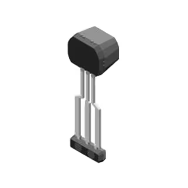
- Part No.:
- ATS344LSPTN-T
- Manufacturer:
- Allegro MicroSystems
- Category:
- Linear, Compass (ICs)
- Package:
- 3-SIP, Formed Leads
- Datasheet:
-
 ATS344LSPTN-T.pdf
- Description:
- SENSOR HALL EFFECT PWM
- Quantity:
- Payment:

- Shipping:

Inventory:2,866
Please send an inquiry. Send us your inquiry, and we will respond immediately.
Product details
Overview
ATS344LSPTN-T from Allegro MicroSystems is a high-precision, back-biased programmable Hall-effect linear sensor IC with two-wire current-mode PWM output, integrated SmCo rare-earth magnetic pellet, and differential Hall sensing architecture. It delivers 12-bit PWM resolution, factory-calibrated sensitivity (0.404 %FSO/G), and operates from 3.75–9.5 V across –40°C to 150°C - optimized for axial position sensing of rotating ferromagnetic targets in automotive transmission and engine timing systems.
For engineers reviewing the ATS344LSPTN-T datasheet, ATS344LSPTN-T pinout, ATS344LSPTN-T application, or ATS344LSPTN-T equivalent, this page provides verified technical context on programmable bandwidth (250–4000 Hz), temperature-compensated offset/sensitivity, EEPROM-based fine adjustment (12-bit QVODC, 12-bit SENSDC), and AEC-Q100 Grade 0 qualification for harsh-environment deployment.
Technical Context
The ATS344LSPTN-T implements a dual-Hall-element analog front end with proprietary four-phase chopper stabilization and dynamic offset cancellation, enabling <±6 G offset drift over –40°C to 150°C and <±1.5% sensitivity drift due to package hysteresis. Its digital signal processing path includes 12-bit ADC conversion, segmented 1st/2nd-order temperature compensation for both sensitivity and magnetic offset, and EEPROM-programmable parameters for bandwidth, clamps, polarity, and fine quiescent output adjustment.
Signal conditioning is fully configurable via serial interface using Manchester-encoded VCC modulation: bandwidth is set by 3-bit F3DB_DC (250–4000 Hz), output clamps by 11-bit CLAMP_HIGH/LOW (0–100% FSO), and sensitivity scaling by 12-bit SENSDC (multiplier 0–8). The device supports hot/cold split TC programming and outputs a stable 850–1150 Hz PWM signal with 96% full-scale duty cycle range.
Key Specifications
| Parameter | Value and Actual Design Meaning |
|---|---|
| Supply Voltage | 3.75–9.5 V - supports unregulated automotive battery rails with internal regulator; enables direct connection to 5 V or 12 V systems without external LDO. |
| PWM Resolution | 12 bits - delivers 4096 discrete output steps across 0–96% duty cycle, enabling sub-degree angular resolution in rotary position sensing. |
| Operating Temperature | –40°C to 150°C - qualified per AEC-Q100 Grade 0; validated for under-hood and transmission applications with no derating required. |
| Bandwidth Programmability | 250–4000 Hz - user-selectable via EEPROM F3DB_DC code; ±5% post-programming tolerance ensures predictable dynamic response. |
| Sensitivity Drift | <±1.5% - measured after temperature cycling (–40°C ↔ 150°C × 1000 cycles); enabled by BiCMOS monolithic integration and active stress compensation. |
| Output Clamping Range | 0–100% FSO - independently programmable high/low clamps (CLAMP_HIGH/LOW) prevent saturation in noisy magnetic environments. |
| Initial Sensitivity | 0.404 %FSO/G - factory-trimmed baseline; adjustable via 12-bit SENSDC multiplier (0–8×) to match target geometry and air gap requirements. |
Pinout & Package
ATS344LSPTN-T is housed in a RoHS-compliant 3-pin SIP (Single In-line Package) with 100% matte tin leadframe plating, designed for through-hole mounting and high-vibration environments. Thermal resistance is 146°C/W (3-pin PCB layout) - optimized for thermal stability in sealed enclosures.
| Pin/Terminal | Circuit Role | Design Meaning |
|---|---|---|
| VCC (Pin 1) | Power input and current-mode PWM output | Supplies internal circuitry and sinks modulated output current (6–16 mA); double-function pin eliminates need for separate output line in two-wire systems. |
| Test (Pin 2) | Production test terminal | Reserved for Allegro factory testing; must be left floating in end-application circuits - no user-accessible function or signal path. |
| GND (Pin 3) | Device ground reference | Provides return path for supply and output current; requires low-impedance connection to system ground plane to maintain noise immunity and thermal stability. |
Key Features
| Feature | Design Value |
|---|---|
| Differential Hall sensing with integrated SmCo pellet | Rejects common-mode magnetic interference and enables axial position detection from rotating ferrous targets without external magnets. |
| EEPROM-programmable bandwidth & clamps | Allows field-tuning of dynamic response (250–4000 Hz) and output range (0–100% FSO) to match mechanical subsystem resonance and signal conditioning requirements. |
| Segmented 1st/2nd-order temperature compensation | Separately programs hot (>25°C) and cold (<25°C) coefficients for sensitivity and offset - eliminates need for external calibration across full automotive temperature range. |
| Four-phase chopper stabilization + active stress compensation | Reduces 1/f noise and lifetime drift; achieves <±6 G offset drift over temperature and <±1.5% sensitivity hysteresis after thermal cycling. |
| AEC-Q100 Grade 0 qualification | Validated for continuous operation at 150°C junction temperature; meets automotive reliability, ESD, and transient immunity requirements without derating. |
Applications
| Automotive Transmission Position Sensing | Engine Crankshaft Timing |
|---|---|
Use Scenario: Detecting axial displacement of gear selector forks or shift actuators in automatic transmissions under high vibration and oil exposure. IC Role / Device Role / Timing Role: Linear Hall-effect sensor providing analog-equivalent PWM output proportional to ferrous target position relative to integrated SmCo bias pellet. Use Value: Eliminates need for external magnet and separate signal conditioning; 12-bit resolution enables <0.1 mm position accuracy at 1 mm air gap with standard 1018 CRS reference target. |
Use Scenario: Monitoring crankshaft rotation angle and speed in ICE engines where space constraints prohibit multi-sensor solutions. IC Role / Device Role / Timing Role: Back-biased differential Hall sensor generating synchronized PWM signal referenced to toothed wheel geometry and thermal environment. Use Value: Factory-calibrated sensitivity and programmable temperature compensation ensure consistent timing accuracy across –40°C cold start to 150°C under-hood operation. |
| Industrial Motor Commutation | Heavy-Duty Brake Pedal Position |
Use Scenario: Rotor position feedback for brushless DC motors in pumps, compressors, and HVAC blowers operating in dusty, high-temperature industrial settings. IC Role / Device Role / Timing Role: High-stability linear Hall sensor delivering real-time angular position via current-mode PWM to motor controller's analog input or dedicated PWM capture peripheral. Use Value: Two-wire interface simplifies wiring harness; programmable bandwidth (up to 4 kHz) supports fast-response commutation up to 20,000 RPM without aliasing. |
Use Scenario: Redundant pedal travel measurement in commercial vehicle braking systems requiring functional safety compliance (ASIL-B capable). IC Role / Device Role / Timing Role: Primary position transducer converting mechanical pedal displacement into fault-tolerant PWM signal with diagnostic capability (EEPROM ECC, UV/OV detection). Use Value: AEC-Q100 qualification and EEPROM error correction enable safe degradation modes; programmable output clamps prevent false trigger during EMI events. |
Equivalent & Alternatives
The following parts are listed as comparable options for similar Hall-effect linear sensor applications.
| Alternative Part | Technical Difference | Application Difference | Selection Advice |
|---|---|---|---|
| Melexis MLX90393 | Triaxis® 3D Hall sensor with I²C/SPI output; no integrated magnetic pellet; 16-bit resolution but fixed 2.7–3.6 V supply. | Requires external magnet and microcontroller interface; suited for 3D position or tilt sensing, not axial-only back-biased configurations. | Select when multi-axis field measurement or digital bus integration is required - not a drop-in replacement for two-wire PWM systems. |
| Allegro ATS6858LSGTN-T | Digital Hall latch with 2-wire current output; no programmable bandwidth, sensitivity, or temperature compensation; fixed 500 Hz bandwidth. | Designed for simple speed/direction detection only; lacks linear output, fine offset adjustment, or EEPROM configuration. | Select for cost-sensitive on/off sensing where programmability and precision linear response are unnecessary. |
Compared with MLX90393 and ATS6858LSGTN-T, ATS344LSPTN-T uniquely combines integrated SmCo biasing, two-wire current-mode PWM, and full EEPROM configurability - making it the only option among the three qualified for AEC-Q100 Grade 0 axial position sensing with field-adjustable performance.
Availability
ATS344LSPTN-T is available at Aetrix Electronics and suitable for automotive transmission control, engine timing systems, and industrial motor commutation requiring stable component supply, long-lifecycle support, and AEC-Q100-compliant sourcing.
Supply support for ATS344LSPTN-T includes scheduled delivery planning, volume procurement assistance, BOM continuity management, traceable sourcing, and lifecycle availability coordination for OEM customers, industrial embedded developers, connected-device designers, and electronics production programs.
Manufacturer
Allegro MicroSystems is a global leader in motion control and energy-efficient power solutions, specializing in Hall-effect sensors, motor drivers, and power ICs for automotive and industrial markets.
The ATS344 product line was engineered specifically for high-reliability axial position sensing in harsh environments - integrating rare-earth biasing, differential Hall architecture, and EEPROM-based field calibration to replace legacy potentiometric and LVDT solutions.
FAQ
What is the maximum programmable bandwidth of the ATS344LSPTN-T?
The ATS344LSPTN-T supports a programmable bandwidth range of 250 Hz to 4000 Hz, set via the 3-bit F3DB_DC EEPROM parameter. This allows system designers to optimize response time versus noise rejection for specific target geometries and mechanical dynamics - for example, selecting 500 Hz for crankshaft timing or 2000 Hz for high-speed transmission actuator control. Bandwidth tolerance is ±5% after programming, ensuring predictable settling behavior.
Does the ATS344LSPTN-T require an external magnet?
No, the ATS344LSPTN-T does not require an external magnet. It integrates a sintered samarium-cobalt (SmCo) rare-earth magnetic pellet that provides a stable, temperature-compensated back-bias field. This enables operation with only a ferromagnetic target (e.g., 1018 CRS steel), eliminating magnet assembly complexity, positional drift, and demagnetization risks - a key differentiator from standard Hall sensors.
How is the ATS344LSPTN-T protected against supply voltage faults?
The ATS344LSPTN-T incorporates undervoltage (UV) and overvoltage (OV) detection with hysteresis. If VCC drops below 3.4 V (UV low threshold), output forces to 100% duty cycle; if VCC rises above 13 V (OV high threshold), output forces to 0% duty cycle. Internal Zener clamp limits forward supply voltage to 20 V. These protections prevent erroneous signals during battery transients and ensure fail-safe behavior in automotive 12 V systems.
Can the ATS344LSPTN-T be reprogrammed in-system?
Yes, the ATS344LSPTN-T supports in-system EEPROM programming via its Manchester-encoded serial interface. An external controller modulates VCC to send commands (Write Access Code, Read/Write registers), and the device responds via ICC modulation. Programming requires a valid access code within tACC (typically 100 ms) after power-up. All customer-programmable parameters - including bandwidth, clamps, sensitivity, and temperature coefficients - can be updated without removing the device from the PCB.
What is the purpose of the Test pin (Pin 2) on the ATS344LSPTN-T?
Pin 2 (Test) on the ATS344LSPTN-T is reserved exclusively for Allegro MicroSystems' internal production testing and has no functional role in end-user applications. It must remain unconnected (floating) in all deployed circuits. No signal, voltage, or load should be applied to this pin, as doing so may interfere with device operation or invalidate AEC-Q100 qualification.
ATS344LSPTN-T Specifications
- Product attributes
- Attribute value
- Manufacturer:
- Allegro MicroSystems
- Series:
- -
- Package/Case:
- 3-SIP, Formed Leads
- Packaging:
- Bulk
- Product Status:
- Obsolete
- Technology:
- Hall Effect
- Axis:
- Single
- Output Type:
- PWM
- Sensing Range:
- ±35mT
- Voltage - Supply:
- 3.75V ~ 9.5V
- Current - Supply (Max):
- 16mA
- Current - Output (Max):
- -
- Resolution:
- 12 b
- Bandwidth:
- 4kHz
- Operating Temperature:
- -40°C ~ 150°C
- Grade:
- Automotive
- Qualification:
- AEC-Q100
- Features:
- Temperature Compensated
- Supplier Device Package:
- -
- Mounting Type:
- Through Hole
ATS344LSPTN-T FAQ
1.How can I place an order for ATS344LSPTN-T through Aetrix?
Please submit a Request for Quotation (RFQ) for ATS344LSPTN-T on Aetrix. Our sales agent will provide a competitive quotation and guide you through the order confirmation once you accept the terms.
2.Are the price and stock information for ATS344LSPTN-T reliable?
The price and inventory of ATS344LSPTN-T are updated periodically and may fluctuate due to market conditions. Stock and pricing data are typically refreshed every 24 hours. Quotation validity for ATS344LSPTN-T is usually 5 days.
3.What payment methods are accepted for ATS344LSPTN-T?
We accept Wire Transfer, PayPal, Credit Card, Western Union, MoneyGram, and Escrow for ATS344LSPTN-T transactions.
Note: Certain payment methods may incur a processing fee.
4.How is shipping managed for ATS344LSPTN-T?
ATS344LSPTN-T orders can be shipped via leading logistics carriers, including DHL, UPS, FedEx, TNT, or Registered Mail.
Once your ATS344LSPTN-T order is processed, you will receive an email with the shipment details and tracking number.
Note: Tracking information may take up to 24 hours to appear. Express delivery typically takes 3–5 business days.
5.How can I obtain technical support or documentation for ATS344LSPTN-T?
For technical support, including ATS344LSPTN-T datasheets, pinout diagrams, or application guidance, please contact our engineering support team. They can provide detailed documentation and assistance for your ATS344LSPTN-T requirements.
6.How does Aetrix verify that ATS344LSPTN-T is sourced from the original manufacturer or authorized distributors?
All ATS344LSPTN-T products on Aetrix are procured from qualified distributors and authorized channels. Our dedicated quality assurance team conducts strict verification, including traceability checks and, if necessary, third-party testing. This ensures that ATS344LSPTN-T meets industry standards.
7.What is the process for return or replacement of ATS344LSPTN-T?
All ATS344LSPTN-T units undergo pre-shipment inspection (PSI). If there is an issue with ATS344LSPTN-T, returns or replacements are accepted under the following conditions:
1.Quantity discrepancies, incorrect items, or visible external defects (such as breakage or corrosion), acknowledged by Aetrix.
2.The issue is reported within 90 days of delivery.
3.The ATS344LSPTN-T part is unused and in its original packaging.
Return procedure for ATS344LSPTN-T:
1.Submit a request within 90 days.
2.Obtain a Return Material Authorization (RMA) from Aetrix.
ATS344LSPTN-T Tags
-
DRV5053VAQDBZR
Texas Instruments
-
MMC5603NJ
Memsic Inc.

-
DRV5055A1QDBZR
Texas Instruments
-
MLX90392ELQ-AAA-011-RE
Melexis Technologies NV

-
CT100LW-HS6
Allegro MicroSystems
-
DRV5056A1ELPGMQ1
Texas Instruments
-
A1304ELHLX-T
Allegro MicroSystems
-
MMC5633NJL
Memsic Inc.
-
A1308KUA-2-T
Allegro MicroSystems
-
A1308KUA-1-T
Allegro MicroSystems
-
SI7210-B-04-IVR
Silicon Labs
-
A1308LLHLT-2-T
Allegro MicroSystems
Tech Hub

A practical engineering and sourcing framework covering lifecycle verification, lifetime-buy calculations, replacement qualification, supplier checks and counterfeit-risk controls.

TTL and CMOS logic families differ in thresholds, loading, output drive, power and timing. This engineering guide compares 74HC and 74HCT, calculates noise margins and checks 3.3 V/5 V compatibility.

A practical engineering guide to 3.3V and 5V logic compatibility, input thresholds, resistor dividers, translator ICs, MOSFET level shifting, I2C pull-ups, timing limits and power-sequencing risks.

The 74HC595 uses push-pull logic outputs, while the TPIC6B595 uses 50 V open-drain DMOS sinks for higher-power loads. This guide compares timing, current limits, 3.3 V interfacing, load wiring, thermal…

The 74HC595 converts serial data into eight stable parallel outputs. This guide covers pin functions, shift and storage timing, OE and MR behavior, drive-current limits, cascading, voltage compatibilit…

A technical comparison of level-sensitive latches and edge-triggered flip-flops, covering timing windows, setup and hold limits, master–slave operation, time borrowing, race-through, HDL inference and…

A D latch stores one bit while Enable controls when data can pass. This reference covers gate-level operation, truth tables, transparency, setup and hold timing, LE versus OE, common ICs and practical …

An SR latch stores one bit through cross-coupled feedback. This engineering reference covers NOR and NAND implementations, truth tables, forbidden-state recovery, gated operation, switch debouncing, fa…

Latch circuits retain one bit through feedback. This technical reference covers SR and D latches, truth tables, transparency, timing limits, latch-versus-flip-flop behavior, applications and common log…

An engineering guide to LED driver operation, constant-current and constant-voltage outputs, linear and switching topologies, dimming, IC selection, calculations, replacement compatibility, and fault c…


