
 My Inquiry
 My Account


Microchip Technology ATSAMR34J18BT-I/7JX
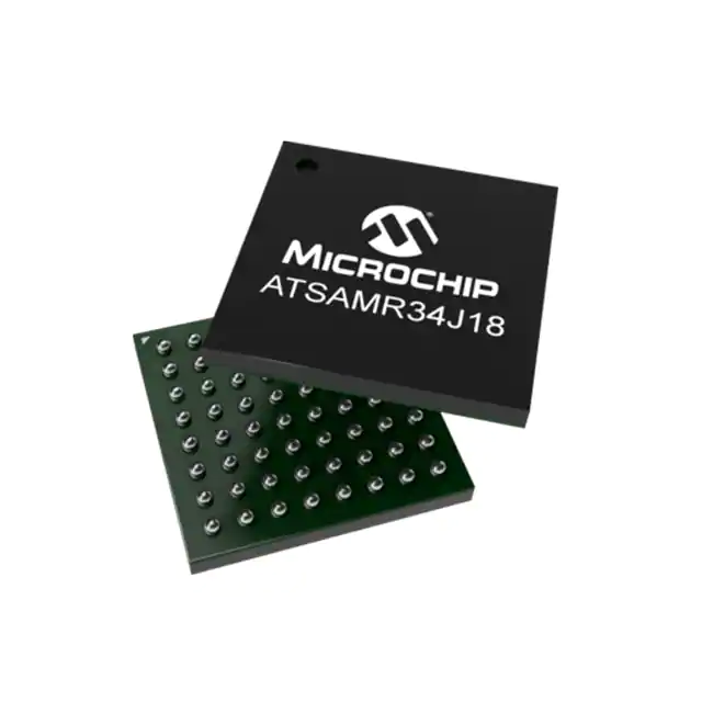
- Part No.:
- ATSAMR34J18BT-I/7JX
- Manufacturer:
- Microchip Technology
- Category:
- RF Transceiver ICs
- Package:
- 64-TFBGA
- Datasheet:
-
 ATSAMR34J18BT-I/7JX.pdf
- Description:
- IC RF TXRX+MCU 802.15.4 64TFBGA
- Quantity:
- Payment:

- Shipping:

Inventory:5,551
Please send an inquiry. Send us your inquiry, and we will respond immediately.
Product details
Overview
ATSAMR34J18BT-I/7JX from Microchip Technology is an ultra-low-power System-in-Package (SiP) microcontroller integrating a 32-bit ARM Cortex-M0+ CPU (48 MHz), 256 KB Flash, 32 KB SRAM, 8 KB low-power SRAM, and a LoRa®/FSK UHF transceiver covering 137–1020 MHz with +20 dBm max output power. It supports USB 2.0 Full-Speed interface and operates from 1.8V–3.6V across –40°C to +85°C for battery-powered remote sensor nodes.
For engineers reviewing the ATSAMR34J18BT-I/7JX datasheet, ATSAMR34J18BT-I/7JX pinout, ATSAMR34J18BT-I/7JX application, or ATSAMR34J18BT-I/7JX equivalent, key selection considerations include integrated LoRa transceiver bandwidth (tri-band sub-GHz), USB-enabled firmware update capability, SleepWalking peripheral wake-up, RF sensitivity down to –136 dBm (LoRaWAN™), and 27 GPIOs in 6×6 mm TFBGA package.
Technical Context
The ATSAMR34J18BT-I/7JX implements a tightly coupled SiP architecture where the ARM Cortex-M0+ MCU communicates with the LoRa transceiver via SERCOM4 (dedicated SPI interface), enabling deterministic packet handling with hardware CRC and automatic frequency control (AFC). Its dual-clock domain includes DFLL48M and FDPLL96M for dynamic voltage/frequency scaling across PL0/PL2 performance levels.
RF subsystem features tri-band coverage (137–175 MHz / 410–525 MHz / 862–1020 MHz), programmable PA_BOOST/RFO_HF/RFI_HF paths, and robust front-end with IIp3 = –11 dBm and blocking immunity optimized for industrial LoRaWAN gateways and end-node repeaters.
Key Specifications
| Parameter | Value and Actual Design Meaning |
|---|---|
| CPU Core | ARM Cortex-M0+, 48 MHz max - delivers 2.46 CoreMark/MHz for efficient LoRa protocol stack execution |
| Memory | 256 KB Flash + 32 KB SRAM + 8 KB LP-SRAM - enables full LoRaWAN Class A/C stack with OTA updates and retained state in backup mode |
| Transceiver Bands | 137–175 MHz / 410–525 MHz / 862–1020 MHz - supports global LoRa regional parameters without external band-switching circuitry |
| Max RF Output | +20 dBm (100 mW) - achieves >168 dB link budget for multi-kilometer rural sensor telemetry |
| RF Sensitivity | –136 dBm (LoRaWAN™) - ensures reliable reception at SF12/125 kHz in noisy industrial environments |
| USB Interface | Full-Speed (12 Mbps) USB 2.0 - enables direct PC-based provisioning, secure bootloader updates, and HID-class device emulation |
| Supply Range | 1.8 V–3.6 V - compatible with single-cell LiSOCl₂, LiMnO₂, or 2×AA alkaline battery systems |
Pinout & Package
ATSAMR34J18BT-I/7JX uses a 64-ball 6×6 mm TFBGA package (7JX) with 27 programmable I/O pins, dedicated RF I/O (RFI_HF, RFO_HF, PA_BOOST), analog supplies (VDDANA, VR_ANA), and USB D+/D− pins (PA24/PA25). Pin functions are multiplexed per PORT configuration registers.
| Pin/Terminal | Circuit Role | Design Meaning |
|---|---|---|
| PA24 / PA25 | USB DM / DP | Full-Speed USB 2.0 differential pair - requires 90 Ω controlled impedance routing and ESD protection for host/device enumeration |
| RFO_HF / PA_BOOST | High-Frequency RF Output | Drives external matching network to +20 dBm - must be isolated from digital noise sources with dedicated GND_RF planes |
| RFI_HF | High-Frequency RF Input | Receives up to –136 dBm signals - requires 50 Ω matched antenna interface and low-noise biasing |
| VBAT_DIG / VBAT_RF | Digital & RF Battery Inputs | Independent supply domains allow separate battery monitoring and RF power gating during deep sleep |
| RESET* | Active-Low Reset | Asynchronous reset input - pulled high internally; external RC filter recommended for brown-out immunity |
Key Features
| Feature | Design Value |
|---|---|
| SleepWalking Peripheral Engine | Enables ADC, TC, or SERCOM to autonomously sample, time, or receive data in Standby mode and wake CPU only on threshold/event - cuts average current to µA range in sensor polling |
| Tri-Band LoRa Transceiver | Single-die RF coverage across all major sub-GHz ISM bands eliminates need for external band-switching SAW filters or PA modules |
| Hardware CRC-32 & Packet Engine | Offloads LoRaWAN MAC layer CRC, preamble detection, and CAD (Channel Activity Detection) - reduces CPU load by ~35% vs software-only implementation |
| USB Bootloader Support | Factory-programmed ROM bootloader allows field firmware updates over USB without JTAG/SWD - critical for deployed sensor networks |
| Configurable Custom Logic (CCL) | Three independent CCL units implement glue logic (e.g., edge-triggered interrupts, PWM gating) in hardware - avoids GPIO toggling overhead in timing-critical RF sync |
Applications
| Smart Utility Metering | Industrial Asset Tracking |
|---|---|
Use Scenario: Battery-powered gas/water meters transmitting hourly consumption data over 5–15 km to fixed gateways in rural areas. IC Role / Device Role / Timing Role: Primary SoC executing LoRaWAN Class A stack, managing AES-128 encryption, and scheduling transmissions using RTC alarm wakeup. Use Value: 20 dBm output + –136 dBm sensitivity enables single-hop transmission without repeaters; 8 KB LP-SRAM retains metering logs during 10-year battery life. | Use Scenario: Ruggedized GPS+LoRa tags on shipping containers reporting location every 6 hours across port logistics zones. IC Role / Device Role / Timing Role: Integrated MCU+RF handles GNSS UART parsing, geofence logic, and adaptive LoRa spreading factor selection based on RSSI feedback. Use Value: SleepWalking ADC monitors battery voltage; USB interface enables depot-level firmware validation before deployment - no JTAG required. |
| Agricultural Soil Monitoring | Smart Building Environmental Sensors |
Use Scenario: Solar-charged soil moisture/temperature nodes deployed in vineyards, transmitting daily aggregated data via LoRa to farm management gateways. IC Role / Device Role / Timing Role: Manages multi-channel ADC sampling, PTC-based touch calibration for enclosure integrity check, and duty-cycled RF transmission aligned to solar harvest peaks. Use Value: Tri-band support allows same BOM across EU (868 MHz) and US (915 MHz) deployments; 48 MHz CPU executes lightweight ML inference for anomaly detection. | Use Scenario: Wall-mounted CO₂/temperature/humidity sensors in office buildings, reporting to BMS via private LoRa network with local edge processing. IC Role / Device Role / Timing Role: Runs real-time air quality algorithm, drives PWM-controlled ventilation fans via TCC outputs, and synchronizes LoRa uplinks with building occupancy schedule. Use Value: Hardware-accelerated CRC and packet engine reduce transmit latency to <12 ms; USB allows IT staff to reconfigure sensor thresholds onsite without tools. |
Equivalent & Alternatives
The following parts are listed as comparable options for similar LoRa system-on-chip applications.
| Alternative Part | Technical Difference | Application Difference | Selection Advice |
|---|---|---|---|
| ATSAMR35J18BT-I/7JX | No USB interface; identical MCU core, memory, RF specs, and pinout - removes USB PHY, DM/DP pins, and associated VREG circuitry | Suitable for cost-sensitive, non-USB field-deployed nodes where firmware updates occur via UART or OTA only | Select when USB provisioning is unnecessary and BOM cost reduction is prioritized over development flexibility |
| RA4M3G20A20001B#AC0 | ARM Cortex-M4F (100 MHz), 1 MB Flash, no integrated RF - requires external SX126x LoRa transceiver via SPI; larger 100-pin LQFP package | Better suited for complex edge AI or gateway applications needing higher compute headroom and dual-band RF expansion | Select when >48 MHz CPU performance, larger code space, or multi-protocol RF (LoRa + BLE/Wi-Fi coexistence) is required |
Compared with ATSAMR34J18BT-I/7JX, ATSAMR35J18BT-I/7JX reduces system cost and layout complexity by removing USB but sacrifices field-serviceability; RA4M3G20A20001B#AC0 offers superior processing for hybrid protocols but increases bill-of-materials count and PCB area by requiring discrete RF components.
Availability
ATSAMR34J18BT-I/7JX is available at Aetrix Electronics and suitable for smart utility metering, industrial asset tracking, agricultural monitoring, and smart building environmental sensing requiring stable component supply across multi-year deployments.
Supply support for ATSAMR34J18BT-I/7JX includes scheduled delivery planning, volume procurement assistance, BOM continuity management, traceable sourcing, and lifecycle availability coordination for OEM customers, industrial embedded developers, connected-device designers, and electronics production programs.
Manufacturer
Microchip Technology Inc. is a leading provider of microcontrollers, analog devices, and connectivity solutions, headquartered in Chandler, Arizona, with global design and manufacturing operations.
The SAM R34 product line is designed specifically for ultra-low-power, long-range IoT end-nodes requiring integrated LoRa connectivity and secure firmware update capability - targeting battery-operated sensor networks compliant with LoRaWAN specifications.
FAQ
What is the maximum RF output power supported by the ATSAMR34J18BT-I/7JX?
The ATSAMR34J18BT-I/7JX supports a maximum RF output power of +20 dBm (100 mW) in the HF band when VDDANA exceeds 2.4 VDC. This rating applies to the RFO_HF and PA_BOOST pins and is validated per LoRa Alliance regional compliance requirements. The device also provides regulated +17 dBm and high-efficiency +13 dBm modes for optimized power-vs-range trade-offs in ATSAMR34J18BT-I/7JX designs.
Does the ATSAMR34J18BT-I/7JX include a built-in USB interface?
Yes, the ATSAMR34J18BT-I/7JX integrates a full-speed (12 Mbps) USB 2.0 interface with embedded host and device functionality, eight endpoints, and on-chip USB PHY. This enables direct connection to PCs for firmware updates, debugging, and HID-class operation - a distinguishing feature versus the USB-less ATSAMR35J18BT-I/7JX variant. The USB interface is implemented on PA24 (DM) and PA25 (DP) pins in the 64-ball TFBGA package.
What are the supported operating temperature and supply voltage ranges for the ATSAMR34J18BT-I/7JX?
The ATSAMR34J18BT-I/7JX is rated for industrial operation from –40°C to +85°C and operates across a supply voltage range of 1.8 V to 3.6 V. These specifications apply to both the MCU core (VDDCORE/VDDIN) and RF subsystem (VDDANA/VR_PA), with separate low-dropout regulators ensuring stable internal voltages. The wide voltage range supports direct integration with primary lithium batteries and energy-harvesting sources in ATSAMR34J18BT-I/7JX-based sensor nodes.
How many general-purpose I/O pins does the ATSAMR34J18BT-I/7JX provide?
The ATSAMR34J18BT-I/7JX provides 27 programmable general-purpose I/O pins, multiplexed across 12 peripheral functions (A–I) including SERCOM, TC/TCC, ADC, AC, PTC, and CCL. These pins are distributed across the 64-ball TFBGA package and support configurable pull-ups/pull-downs, slew rate control, and glitch filtering. All 27 GPIOs remain functional in Standby sleep mode when configured for wake-up events in ATSAMR34J18BT-I/7JX applications.
What LoRa modulation schemes and frequency bands does the ATSAMR34J18BT-I/7JX support?
The ATSAMR34J18BT-I/7JX supports LoRa®, (G)FSK, (G)MSK, and OOK modulation schemes. Its integrated transceiver covers three licensed-free sub-GHz bands: 137–175 MHz, 410–525 MHz, and 862–1020 MHz - enabling global deployment without hardware changes. Band selection is software-configurable via register settings, and LoRaWAN regional parameters (e.g., EU868, US915) are supported through certified stack implementations for ATSAMR34J18BT-I/7JX.
ATSAMR34J18BT-I/7JX Specifications
- Product attributes
- Attribute value
- Manufacturer:
- Microchip Technology
- Series:
- -
- Package/Case:
- 64-TFBGA
- Packaging:
- Tape & Reel (TR)
- Product Status:
- Active
- Programmable:
- Not Verified
- Type:
- TxRx + MCU
- RF Family/Standard:
- 802.15.4
- Protocol:
- LoRa™
- Modulation:
- FSK, GFSK, GMSK, MSK, OOK
- Frequency:
- 137MHz ~ 175MHz, 410MHz ~ 525MHz, 862MHz ~ 1.02GHz
- Data Rate (Max):
- -
- Power - Output:
- 20dBm
- Sensitivity:
- -148dBm
- Memory Size:
- 256kB Flash, 32kB SRAM
- Serial Interfaces:
- I2S, SPI, USART, USB
- GPIO:
- 27
- Voltage - Supply:
- 1.8V ~ 3.63V
- Current - Receiving:
- 14.8mA ~ 15.8mA
- Current - Transmitting:
- 32.5mA ~ 94.5mA
- Operating Temperature:
- -40°C ~ 85°C
- Grade:
- -
- Qualification:
- -
- Supplier Device Package:
- 64-TFBGA (6x6)
ATSAMR34J18BT-I/7JX FAQ
1.How can I place an order for ATSAMR34J18BT-I/7JX through Aetrix?
Please submit a Request for Quotation (RFQ) for ATSAMR34J18BT-I/7JX on Aetrix. Our sales agent will provide a competitive quotation and guide you through the order confirmation once you accept the terms.
2.Are the price and stock information for ATSAMR34J18BT-I/7JX reliable?
The price and inventory of ATSAMR34J18BT-I/7JX are updated periodically and may fluctuate due to market conditions. Stock and pricing data are typically refreshed every 24 hours. Quotation validity for ATSAMR34J18BT-I/7JX is usually 5 days.
3.What payment methods are accepted for ATSAMR34J18BT-I/7JX?
We accept Wire Transfer, PayPal, Credit Card, Western Union, MoneyGram, and Escrow for ATSAMR34J18BT-I/7JX transactions.
Note: Certain payment methods may incur a processing fee.
4.How is shipping managed for ATSAMR34J18BT-I/7JX?
ATSAMR34J18BT-I/7JX orders can be shipped via leading logistics carriers, including DHL, UPS, FedEx, TNT, or Registered Mail.
Once your ATSAMR34J18BT-I/7JX order is processed, you will receive an email with the shipment details and tracking number.
Note: Tracking information may take up to 24 hours to appear. Express delivery typically takes 3–5 business days.
5.How can I obtain technical support or documentation for ATSAMR34J18BT-I/7JX?
For technical support, including ATSAMR34J18BT-I/7JX datasheets, pinout diagrams, or application guidance, please contact our engineering support team. They can provide detailed documentation and assistance for your ATSAMR34J18BT-I/7JX requirements.
6.How does Aetrix verify that ATSAMR34J18BT-I/7JX is sourced from the original manufacturer or authorized distributors?
All ATSAMR34J18BT-I/7JX products on Aetrix are procured from qualified distributors and authorized channels. Our dedicated quality assurance team conducts strict verification, including traceability checks and, if necessary, third-party testing. This ensures that ATSAMR34J18BT-I/7JX meets industry standards.
7.What is the process for return or replacement of ATSAMR34J18BT-I/7JX?
All ATSAMR34J18BT-I/7JX units undergo pre-shipment inspection (PSI). If there is an issue with ATSAMR34J18BT-I/7JX, returns or replacements are accepted under the following conditions:
1.Quantity discrepancies, incorrect items, or visible external defects (such as breakage or corrosion), acknowledged by Aetrix.
2.The issue is reported within 90 days of delivery.
3.The ATSAMR34J18BT-I/7JX part is unused and in its original packaging.
Return procedure for ATSAMR34J18BT-I/7JX:
1.Submit a request within 90 days.
2.Obtain a Return Material Authorization (RMA) from Aetrix.
ATSAMR34J18BT-I/7JX Tags

-
ESP32-D0WD-V3
Espressif Systems

-
ESP8266EX
Espressif Systems

-
ESP32-S3
Espressif Systems

-
NRF24L01P-R7
Nordic Semiconductor ASA
-
NRF24L01P-R
Nordic Semiconductor ASA

-
ESP32-U4WDH
Espressif Systems

-
DA14531-00000OG2
Renesas
-
ESP32-C6FH4
Espressif Systems

-
DA14531-00000FX2
Renesas
-
NRF24L01P-T
Nordic Semiconductor ASA

-
NRF52810-QCAA-R
Nordic Semiconductor ASA
-
ESP32-S3FN8
Espressif Systems
Tech Hub

TTL and CMOS logic families differ in thresholds, loading, output drive, power and timing. This engineering guide compares 74HC and 74HCT, calculates noise margins and checks 3.3 V/5 V compatibility.

A practical engineering guide to 3.3V and 5V logic compatibility, input thresholds, resistor dividers, translator ICs, MOSFET level shifting, I2C pull-ups, timing limits and power-sequencing risks.

The 74HC595 uses push-pull logic outputs, while the TPIC6B595 uses 50 V open-drain DMOS sinks for higher-power loads. This guide compares timing, current limits, 3.3 V interfacing, load wiring, thermal…

The 74HC595 converts serial data into eight stable parallel outputs. This guide covers pin functions, shift and storage timing, OE and MR behavior, drive-current limits, cascading, voltage compatibilit…

A technical comparison of level-sensitive latches and edge-triggered flip-flops, covering timing windows, setup and hold limits, master–slave operation, time borrowing, race-through, HDL inference and…

A D latch stores one bit while Enable controls when data can pass. This reference covers gate-level operation, truth tables, transparency, setup and hold timing, LE versus OE, common ICs and practical …

An SR latch stores one bit through cross-coupled feedback. This engineering reference covers NOR and NAND implementations, truth tables, forbidden-state recovery, gated operation, switch debouncing, fa…

Latch circuits retain one bit through feedback. This technical reference covers SR and D latches, truth tables, transparency, timing limits, latch-versus-flip-flop behavior, applications and common log…

An engineering guide to LED driver operation, constant-current and constant-voltage outputs, linear and switching topologies, dimming, IC selection, calculations, replacement compatibility, and fault c…

Operational amplifier guide covering op amp basics, feedback, ideal vs real op amps, common configurations, buffer circuits, offset, bias current, gain-bandwidth, slew rate, rail-to-rail limits and sel…


