
 My Inquiry
 My Account


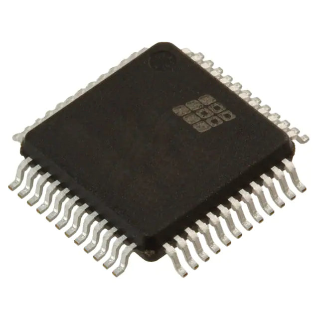
Microchip Technology ATV2500BQ-25JI
- Part No.:
- ATV2500BQ-25JI
- Manufacturer:
- Microchip Technology
- Package:
- 44-LCC (J-Lead)
- Datasheet:
-
 ATV2500BQ-25JI.pdf
- Description:
- IC CPLD 24MC 25NS 44PLCC
- Quantity:
- Payment:

- Shipping:

Inventory:3,836
Please send an inquiry. Send us your inquiry, and we will respond immediately.
Product details
Overview
ATV2500BQ-25JI from Atmel is a high-density, UV-erasable programmable logic device (PLD) in 44-lead PLCC package, delivering 7 ns pin-to-pin delay, 416 product terms, 48 flip-flops, and 24 macrocells for complex combinatorial and registered logic. It operates across -40°C to +85°C industrial temperature range with 30 mA standby ICC and supports both D- and T-type register configuration per macrocell.
For engineers reviewing the ATV2500BQ-25JI datasheet, ATV2500BQ-25JI pinout, ATV2500BQ-25JI application, or ATV2500BQ-25JI equivalent, this device serves as a speed- and power-optimized upgrade path from ATV2500H/L in industrial control, legacy system re-engineering, and FPGA prototyping support where reprogrammability and deterministic timing are critical.
Technical Context
The ATV2500BQ-25JI implements a fully connected universal AND-OR array with 172 inputs per AND gate and 4 product terms feeding each sum term. All 38 logic pins and all 48 flip-flop outputs feed directly into the global bus, enabling full interconnectivity without routing constraints.
Each of its 24 macrocells contains two independently configurable flip-flops (D- or T-type), three sum terms combinable into up to 12-product-term logic blocks, and dedicated product-term clocking, asynchronous reset, and output enable-supporting buried state machines, multi-clock domains, and true bi-directional I/O with independent feedback paths.
Key Specifications
| Parameter | Value and Actual Design Meaning |
|---|---|
| Propagation Delay (tPD) | 25 ns - guarantees worst-case input-to-output timing for synchronous design closure at ≤31 MHz external feedback frequency |
| Pin-to-Pin Delay (tCOS) | 12 ns - defines minimum clock-to-output latency for registered outputs under industrial conditions |
| Standby Current (ICC) | 30 mA - enables low-power operation in always-on industrial modules without thermal derating |
| Logic Density | 2500 usable gates - achieves >80% gate utilization via flexible macrocell feedback and sum-term combining |
| Macrocells / Flip-flops | 24 macrocells, 48 flip-flops - supports dual-register per I/O for complex state retention and data pipelining |
| Operating Temperature | -40°C to +85°C - qualified for industrial-grade embedded systems with no derating required |
| Supply Voltage | 5 V ±10% - compatible with legacy 5 V TTL/CMOS system rails and noise-tolerant signaling |
Pinout & Package
ATV2500BQ-25JI uses a 44-lead Plastic J-Leaded Chip Carrier (PLCC) package with 16.5 mm × 16.5 mm body, 1.27 mm lead pitch, and JEDEC MS-018 AC standard footprint. Pin 4 and pin 26 are not required for PLCC versions and may be left unconnected.
| Pin/Terminal | Circuit Role | Design Meaning |
|---|---|---|
| CLK/IN | Primary clock or logic input | Accepts either edge-triggered clock signal or general-purpose input; selectable per macrocell for pin- or product-term clocking |
| I/O0–I/O23 | Bi-directional I/O buffers | Even-numbered (I/O0,2,4…) and odd-numbered (I/O1,3,5…) pins support independent direction control and registered/combinatorial modes |
| IN1–IN14 | Dedicated logic inputs | 14 primary array inputs with true/complement pairs routed to global bus; feed all macrocells simultaneously |
| VCC | +5 V supply | Two dedicated VCC pins (pins 11 & 12) reduce IR drop and improve noise immunity in high-speed switching |
| GND | Ground reference | Three GND pins (pins 17, 18, 30) provide low-inductance return paths for I/O and core logic |
Key Features
| Feature | Design Value |
|---|---|
| Fully connected logic array | Every macrocell receives all 38 inputs and 48 feedback signals - eliminates placement congestion and ensures 100% routability |
| Selectable D- or T-type flip-flops | Per-macrocell register type selection enables JK/SR synthesis and efficient state encoding without extra product terms |
| Buried combinatorial feedback | Q2 register bypass allows direct D/T2-to-array feedback - expands effective logic density without consuming I/O pins |
| Independent clock & reset per flip-flop | Each of 48 registers has dedicated product-term clock and asynchronous reset - supports heterogeneous clock domains |
| Preload and observability mode | 12 registers accessible via SMP pin 42 preload; buried Q2 bank observable on outputs via pin 2 - simplifies boundary-scan test |
Applications
| Industrial Motion Controller | Legacy Bus Interface Adapter |
|---|---|
Use Scenario: Real-time coordination of stepper motor phases, limit switch monitoring, and encoder feedback decoding in CNC equipment. IC Role / Device Role / Timing Role: Configurable logic engine implementing synchronous state machines with deterministic 12 ns clock-to-output timing and dual-register pipeline stages. Use Value: Replaces multiple discrete SSI chips and PALs while maintaining full compatibility with existing 5 V backplane timing and industrial temperature requirements. |
Use Scenario: Bridging ISA or VMEbus peripherals to modern microcontrollers via protocol translation and handshaking logic. IC Role / Device Role / Timing Role: Programmable glue logic handling address decoding, strobe generation, and bus arbitration with 25 ns propagation delay margin. Use Value: Eliminates custom ASIC development; enables field-upgradable interface logic without PCB redesign due to UV-erasable reprogrammability. |
| Avionics Test Fixture Logic | Medical Imaging Signal Processor |
Use Scenario: Stimulus generation and response capture for DO-254-compliant LRUs during burn-in and functional test. IC Role / Device Role / Timing Role: Deterministic pattern generator with synchronous preset/reset and preload capability for repeatable fault injection sequences. Use Value: Meets MIL-STD-883 Class B requirements; supports traceable test vector loading via SMP pin 42 and observability of internal registers. |
Use Scenario: Pixel clock domain crossing, FIFO control, and gamma correction coefficient sequencing in ultrasound front-end modules. IC Role / Device Role / Timing Role: Dual-clock domain synchronizer with independent flip-flop clocks and 30 mA standby current enabling low-power idle states. Use Value: Reduces component count vs. discrete logic; maintains sub-100 ns timing margins across analog/digital boundaries in safety-critical imaging paths. |
Equivalent & Alternatives
The following parts are listed as comparable options for similar programmable logic device applications.
| Alternative Part | Technical Difference | Application Difference | Selection Advice |
|---|---|---|---|
| ATV2500B-25JI | Higher standby current (110 mA vs. 30 mA); same speed grade and pinout | Less suitable for thermally constrained or battery-backed industrial modules | Select when legacy software toolchain requires exact ATV2500B family ID and power budget permits |
| ATV2500BL-25JI | Ultra-low standby current (2 mA); identical logic architecture and timing | Requires additional programming voltage setup; not UV-erasable in-system | Choose for always-on remote sensors where power is critical and reprogramming is infrequent |
Compared with ATV2500B-25JI, ATV2500BQ-25JI reduces standby power by 73% without sacrificing speed or logic density; compared with ATV2500BL-25JI, it retains full UV-erasability and in-system reprogrammability at the cost of higher quiescent current-making it optimal for field-serviceable industrial controllers.
Availability
ATV2500BQ-25JI is available at Aetrix Electronics and suitable for industrial motion control, avionics test fixtures, and medical imaging signal processing requiring stable component supply across extended temperature ranges and long production lifecycles.
Supply support for ATV2500BQ-25JI includes scheduled delivery planning, volume procurement assistance, BOM continuity management, traceable sourcing, and lifecycle availability coordination for OEM customers, industrial embedded developers, connected-device designers, and electronics production programs.
Manufacturer
Atmel Corporation (now part of Microchip Technology) is a semiconductor manufacturer specializing in non-volatile memory, microcontrollers, and programmable logic devices using advanced CMOS EPROM processes.
The ATV2500B series was designed as a high-density, reprogrammable alternative to bipolar PLDs for industrial and military applications demanding field-upgradable logic with deterministic timing and proven reliability.
FAQ
What is the maximum operating frequency supported by ATV2500BQ-25JI?
The ATV2500BQ-25JI supports up to 31 MHz external feedback operation (FMAXS = 1/(tSIS + tCOS)) and 23 MHz with no feedback (FMAXS = 1/tPS), based on its 12 ns clock-to-output and 25 ns input setup timing under industrial conditions. These values are measured with 1.5 V threshold and 0 V/3.0 V driving levels per the datasheet AC characterization.
Does ATV2500BQ-25JI require UV erasure before reprogramming?
Yes, ATV2500BQ-25JI is a UV-erasable EPROM-based PLD and must be exposed to 253.7 nm ultraviolet light for ≥20 minutes at 12,000 µW/cm² intensity to fully erase the logic pattern before reprogramming. The device features a quartz window in its PLCC package to enable this process, and an opaque label is recommended during normal operation to prevent accidental erasure.
Can ATV2500BQ-25JI replace ATV2500H/L in existing designs without board changes?
Yes, ATV2500BQ-25JI is backward compatible with ATV2500H/L software and shares identical pinout for PLCC packages. However, ATV2500H/L require additional GND connections not needed by ATV2500BQ-25JI (pins 4 and 26 are NC), so PCB layout remains unchanged but unused pads may remain unconnected.
What is the purpose of SMP pin 42 and pin 2 on ATV2500BQ-25JI?
SMP pin 42 enables preload mode (10.25–10.75 V) to asynchronously load data from I/O pins into selected registers; pin 2 enables Q2 observability mode (same voltage range) to expose buried register contents on associated outputs when OE is active. Both functions support IEEE 1149.1-compatible boundary-scan testing and in-system verification.
How does the power-up reset behavior of ATV2500BQ-25JI affect system initialization?
ATV2500BQ-25JI performs automatic power-up reset at VCC ≈ 4.15 V (VRST typ), forcing all 48 registers to low state within 600–1000 ns (tPR). This requires monotonic VCC ramp-up and adherence to input setup times before first clock edge-ensuring deterministic initial state without external reset circuitry in compliant systems.
ATV2500BQ-25JI Specifications
- Product attributes
- Attribute value
- Manufacturer:
- Microchip Technology
- Series:
- ATV2500B(L) and BQ(L)
- Package/Case:
- 44-LCC (J-Lead)
- Packaging:
- Tube
- Product Status:
- Obsolete
- Programmable:
- Not Verified
- Programmable Type:
- OTP
- Delay Time tpd(1) Max:
- 25 ns
- Voltage Supply - Internal:
- 4.5V ~ 5.5V
- Number of Logic Elements/Blocks:
- -
- Number of Macrocells:
- 24
- Number of Gates:
- -
- Number of I/O:
- 24
- Operating Temperature:
- -40°C ~ 85°C (TA)
- Grade:
- -
- Qualification:
- -
- Mounting Type:
- Surface Mount
- Supplier Device Package:
- 44-PLCC (16.6x16.6)
ATV2500BQ-25JI FAQ
1.How can I place an order for ATV2500BQ-25JI through Aetrix?
Please submit a Request for Quotation (RFQ) for ATV2500BQ-25JI on Aetrix. Our sales agent will provide a competitive quotation and guide you through the order confirmation once you accept the terms.
2.Are the price and stock information for ATV2500BQ-25JI reliable?
The price and inventory of ATV2500BQ-25JI are updated periodically and may fluctuate due to market conditions. Stock and pricing data are typically refreshed every 24 hours. Quotation validity for ATV2500BQ-25JI is usually 5 days.
3.What payment methods are accepted for ATV2500BQ-25JI?
We accept Wire Transfer, PayPal, Credit Card, Western Union, MoneyGram, and Escrow for ATV2500BQ-25JI transactions.
Note: Certain payment methods may incur a processing fee.
4.How is shipping managed for ATV2500BQ-25JI?
ATV2500BQ-25JI orders can be shipped via leading logistics carriers, including DHL, UPS, FedEx, TNT, or Registered Mail.
Once your ATV2500BQ-25JI order is processed, you will receive an email with the shipment details and tracking number.
Note: Tracking information may take up to 24 hours to appear. Express delivery typically takes 3–5 business days.
5.How can I obtain technical support or documentation for ATV2500BQ-25JI?
For technical support, including ATV2500BQ-25JI datasheets, pinout diagrams, or application guidance, please contact our engineering support team. They can provide detailed documentation and assistance for your ATV2500BQ-25JI requirements.
6.How does Aetrix verify that ATV2500BQ-25JI is sourced from the original manufacturer or authorized distributors?
All ATV2500BQ-25JI products on Aetrix are procured from qualified distributors and authorized channels. Our dedicated quality assurance team conducts strict verification, including traceability checks and, if necessary, third-party testing. This ensures that ATV2500BQ-25JI meets industry standards.
7.What is the process for return or replacement of ATV2500BQ-25JI?
All ATV2500BQ-25JI units undergo pre-shipment inspection (PSI). If there is an issue with ATV2500BQ-25JI, returns or replacements are accepted under the following conditions:
1.Quantity discrepancies, incorrect items, or visible external defects (such as breakage or corrosion), acknowledged by Aetrix.
2.The issue is reported within 90 days of delivery.
3.The ATV2500BQ-25JI part is unused and in its original packaging.
Return procedure for ATV2500BQ-25JI:
1.Submit a request within 90 days.
2.Obtain a Return Material Authorization (RMA) from Aetrix.
ATV2500BQ-25JI Tags
-
5M40ZE64C5N
Intel
-
ATF1502ASV-15AU44
Microchip Technology
-
5M80ZE64C5N
Intel
-
5M80ZT100C5N
Intel
-
ATF1502AS-10AU44
Microchip Technology
-
ATF1502AS-10JU44
Microchip Technology
-
5M80ZE64I5N
Intel
-
5M80ZT100I5N
Intel
-
LC4032V-75TN48C
Lattice Semiconductor Corporation
-
ATF1504ASV-15AU44
Microchip Technology
-
ATF1504AS-10JU44
Microchip Technology
-
5M160ZE64C5N
Intel
Tech Hub

TTL and CMOS logic families differ in thresholds, loading, output drive, power and timing. This engineering guide compares 74HC and 74HCT, calculates noise margins and checks 3.3 V/5 V compatibility.

A practical engineering guide to 3.3V and 5V logic compatibility, input thresholds, resistor dividers, translator ICs, MOSFET level shifting, I2C pull-ups, timing limits and power-sequencing risks.

The 74HC595 uses push-pull logic outputs, while the TPIC6B595 uses 50 V open-drain DMOS sinks for higher-power loads. This guide compares timing, current limits, 3.3 V interfacing, load wiring, thermal…

The 74HC595 converts serial data into eight stable parallel outputs. This guide covers pin functions, shift and storage timing, OE and MR behavior, drive-current limits, cascading, voltage compatibilit…

A technical comparison of level-sensitive latches and edge-triggered flip-flops, covering timing windows, setup and hold limits, master–slave operation, time borrowing, race-through, HDL inference and…

A D latch stores one bit while Enable controls when data can pass. This reference covers gate-level operation, truth tables, transparency, setup and hold timing, LE versus OE, common ICs and practical …

An SR latch stores one bit through cross-coupled feedback. This engineering reference covers NOR and NAND implementations, truth tables, forbidden-state recovery, gated operation, switch debouncing, fa…

Latch circuits retain one bit through feedback. This technical reference covers SR and D latches, truth tables, transparency, timing limits, latch-versus-flip-flop behavior, applications and common log…

An engineering guide to LED driver operation, constant-current and constant-voltage outputs, linear and switching topologies, dimming, IC selection, calculations, replacement compatibility, and fault c…

Operational amplifier guide covering op amp basics, feedback, ideal vs real op amps, common configurations, buffer circuits, offset, bias current, gain-bandwidth, slew rate, rail-to-rail limits and sel…


