
 My Inquiry
 My Account


Diodes Incorporated AZ317HTR-E1
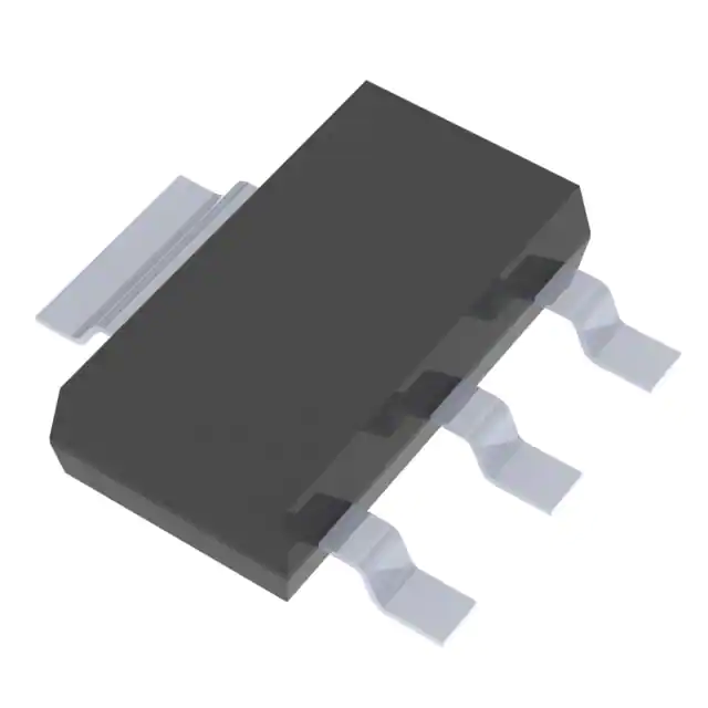
- Part No.:
- AZ317HTR-E1
- Manufacturer:
- Diodes Incorporated
- Package:
- TO-261-4, TO-261AA
- Datasheet:
-
 AZ317HTR-E1.pdf
- Description:
- IC REG LINEAR POS ADJ 1A SOT223
- Quantity:
- Payment:

- Shipping:

Inventory:2,669
Please send an inquiry. Send us your inquiry, and we will respond immediately.
Product details
Overview
AZ317HTR-E1 from Diodes Incorporated is an adjustable three-terminal positive linear voltage regulator delivering 1A output current with 1.2V dropout at full load, ±1% reference voltage accuracy (1.25V), and integrated thermal shutdown and current limiting. It operates from 0°C to +125°C junction temperature and is used in PC motherboard VRMs, LCD monitor power rails, and graphics card auxiliary supplies.
For engineers reviewing the AZ317HTR-E1 datasheet, AZ317HTR-E1 pinout, AZ317HTR-E1 application, or AZ317HTR-E1 equivalent, this device supports precision adjustable low-dropout regulation in space-constrained SOT223 layouts, requires external R1/R2 for VOUT programming down to 1.25V, and demands attention to input/output capacitor selection (CIN ≥ 0.1µF, CO ≥ 1.0µF) for stability and transient response.
Technical Context
The AZ317HTR-E1 implements a trimmed bandgap reference with 1.25V nominal output voltage, enabling precise VOUT = 1.25V × (1 + R2/R1) + IADJ×R2 adjustment. Its internal current limiter is factory-trimmed to 1.5A typical short-circuit current and maintains stable operation across 3V ≤ (VIN–VOUT) ≤ 15V input differential range.
Thermal protection activates at +150°C junction temperature with +25°C hysteresis, and line/load regulation are specified at 0.01%/V and 0.2% respectively. The device supports continuous operation up to 125°C ambient when mounted on PCBs with adequate copper pour per SOT223 thermal pad layout guidelines.
Key Specifications
| Parameter | Value and Actual Design Meaning |
|---|---|
| Output Current | 1A continuous - supports high-current point-of-load regulation for CPU core or GPU memory rails. |
| Dropout Voltage | 1.2V at 1A - enables operation with minimal VIN–VOUT margin, critical for 3.3V/2.5V/1.8V outputs from 5V or 12V rails. |
| Reference Voltage | 1.25V ±1% - ensures output accuracy within ±12.5mV at 1.25V, translating to ±33mV at 3.3V output with standard resistor divider. |
| Line Regulation | 0.01%/V - limits output drift to ±0.33mV per volt of input variation, essential for stable supply under varying input conditions. |
| Load Regulation | 0.2% - guarantees ≤6.6mV output change from 10mA to 1A load, suitable for noise-sensitive analog circuitry. |
| Ripple Rejection | 75dB at 120Hz - suppresses AC ripple from switching pre-regulators, preserving clean DC for ADC references or PLLs. |
| Junction Temp Range | 0°C to +125°C - validated for industrial-grade operation without derating in enclosed chassis environments. |
Pinout & Package
Package: SOT223 - surface-mount, thermally enhanced 4-pin package with exposed thermal pad (pin 4 internally connected to VOUT). Pin 1: INPUT; Pin 2: OUTPUT; Pin 3: ADJ; Pin 4: VOUT (thermal tab).
| Pin/Terminal | Circuit Role | Design Meaning |
|---|---|---|
| 1 (INPUT) | Unregulated Input Supply | Accepts 3.3V to 20V input; requires ≥0.1µF ceramic bypass capacitor placed within 5mm of pin for EMI suppression. |
| 2 (OUTPUT) | Regulated Output Node | Delivers adjustable VOUT; connects directly to load and 1.0µF tantalum or low-ESR ceramic output capacitor for loop stability. |
| 3 (ADJ) | Reference Feedback Input | Senses voltage divider (R1/R2); draws ≤100µA-enables high-resistor values (e.g., 240Ω/1.8kΩ) to minimize quiescent current. |
| 4 (VOUT / Thermal Pad) | Output Power & Thermal Path | Internally tied to OUTPUT pin; must be soldered to ≥250mm² copper pour for θJA ≤ 65°C/W and full 1A capability. |
Key Features
| Feature | Design Value |
|---|---|
| Trimmed Bandgap Reference | 1.25V ±1% tolerance eliminates need for post-production calibration in production test flows. |
| Factory-Trimmed Current Limit | 1.5A typical short-circuit current enables predictable fault behavior without external sensing resistors. |
| On-Chip Thermal Shutdown | +150°C activation with +25°C hysteresis prevents latch-up during sustained overload and allows safe auto-recovery. |
| Low Dropout Architecture | 1.2V dropout at 1A permits use with 5V input to generate 3.3V/2.5V outputs where space prohibits buck converters. |
| Lead-Free & Green Compliance | SOT223 package meets RoHS 3 and halogen-free (<900ppm Br/Cl, <1000ppm Sb) requirements for global environmental compliance. |
Applications
| PC Motherboard VRM | LCD Monitor Backlight Supply |
|---|---|
Use Scenario: Regulating +3.3V standby rail for southbridge, USB controllers, and SMBus interface logic. IC Role / Device Role / Timing Role: Primary linear regulator providing low-noise, fast-transient 3.3V supply independent of main ATX 12V/5V rails. Use Value: 75dB ripple rejection and 0.2% load regulation ensure stable logic levels during USB hot-plug events and PCIe enumeration sequences. |
Use Scenario: Generating adjustable bias voltage (1.8V–5.0V) for LED driver ICs in edge-lit LCD panels. IC Role / Device Role / Timing Role: Programmable analog voltage source setting LED string current via external DAC or microcontroller feedback loop. Use Value: 1.25V reference accuracy and 0.01%/V line regulation maintain consistent backlight brightness across wide input voltage swings from AC-DC adapter. |
| Graphics Card Memory Rail | Network Interface Card (NIC) PHY Supply |
Use Scenario: Providing clean +1.8V or +1.5V supply to GDDR5/GDDR6 memory interfaces on discrete GPUs. IC Role / Device Role / Timing Role: Low-noise local regulator decoupling high-speed memory bus from noisy GPU core switching noise. Use Value: RMS output noise of 0.003% of VOUT minimizes jitter on memory clock edges, preserving signal integrity at >10Gbps data rates. |
Use Scenario: Powering Ethernet PHY transceivers (e.g., Marvell 88E1512) requiring stable +2.5V or +3.3V analog supply. IC Role / Device Role / Timing Role: Precision voltage source for PHY analog front-end, including SERDES CDR and line driver stages. Use Value: ±1% reference accuracy and thermal stability of ≤1% over 0–125°C ensure compliant Ethernet signal amplitude and rise/fall times across operating temperature range. |
Equivalent & Alternatives
The following parts are listed as comparable options for similar adjustable LDO regulator applications.
| Alternative Part | Technical Difference | Application Difference | Selection Advice |
|---|---|---|---|
| LM317LDR2G | Higher dropout (1.7V @ 100mA), lower max current (100mA), TO92 package only. | Not suitable for 1A loads; limited thermal performance in SMT designs. | Select only for low-power, cost-sensitive prototypes where 100mA suffices and through-hole assembly is acceptable. |
| TLV1117-33CDCYR | Fixed 3.3V output, 1.2V dropout @ 800mA, SOT223 package, no ADJ pin. | Lacks adjustability; cannot support variable VOUT or 1.25V–15V range. | Choose when fixed 3.3V output is sufficient and board space allows same footprint but simplified BOM. |
Compared with LM317LDR2G and TLV1117-33CDCYR, AZ317HTR-E1 uniquely delivers 1A adjustable regulation in SOT223 with 1.2V dropout and ±1% accuracy-making it the only option among the three capable of replacing legacy LM317-based 1A designs while maintaining footprint compatibility and thermal performance.
Availability
AZ317HTR-E1 is available at Aetrix Electronics and suitable for PC motherboard VRMs, LCD monitor power subsystems, and graphics card memory rail designs requiring stable component supply with RoHS 3 and halogen-free compliance.
Supply support for AZ317HTR-E1 includes scheduled delivery planning, volume procurement assistance, BOM continuity management, traceable sourcing, and lifecycle availability coordination for OEM customers, industrial embedded developers, connected-device designers, and electronics production programs.
Manufacturer
Diodes Incorporated is a global manufacturer of discrete semiconductors and analog ICs, specializing in high-reliability power management, signal integrity, and protection solutions for industrial, computing, and consumer markets.
AZ317 belongs to Diodes' precision adjustable LDO regulator product line, engineered specifically for high-current, low-dropout point-of-load regulation in space-constrained computing and display applications where thermal efficiency and output accuracy are critical.
FAQ
What is the minimum required output capacitor for stable operation?
The AZ317HTR-E1 requires a minimum 1.0µF tantalum or low-ESR ceramic capacitor at the OUTPUT pin to ensure phase margin and prevent oscillation. For optimal transient response under 1A load steps, a 10µF tantalum capacitor is recommended, as verified in the datasheet's load transient response plots on page 6.
Can AZ317HTR-E1 be used in parallel for higher current?
No-AZ317HTR-E1 lacks built-in current-sharing features such as remote sensing or master-slave control. Parallel connection risks thermal runaway due to mismatched reference voltages and dropout characteristics; Diodes does not characterize or recommend paralleling this device.
What is the maximum allowable input voltage?
The absolute maximum input voltage is 20V, but the recommended operating range is VIN ≤ VOUT + 15V per datasheet Section 4. Exceeding VOUT + 15V increases power dissipation beyond safe limits-even at light loads-and may trigger thermal shutdown or degrade long-term reliability.
How does the ADJ pin current affect output accuracy?
Adjust pin current is specified ≤100µA and changes by ≤5µA over temperature and load. When using standard R1=240Ω, this introduces ≤0.24mV error in VREF-negligible versus the ±12.5mV (±1%) reference tolerance, confirming that high-value R2 resistors do not compromise accuracy.
AZ317HTR-E1 Specifications
- Product attributes
- Attribute value
- Manufacturer:
- Diodes Incorporated
- Series:
- -
- Package/Case:
- TO-261-4, TO-261AA
- Packaging:
- Tape & Reel (TR)
- Product Status:
- Obsolete
- Output Configuration:
- Positive
- Output Type:
- Adjustable
- Number of Regulators:
- 1
- Voltage - Input (Max):
- 15V
- Voltage - Output (Min/Fixed):
- 1.25V
- Voltage - Output (Max):
- 13.7V
- Voltage Dropout (Max):
- 1.3V @ 1A
- Current - Output:
- 1A
- Current - Quiescent (Iq):
- -
- Current - Supply (Max):
- -
- PSRR:
- 75dB (120Hz)
- Control Features:
- -
- Protection Features:
- Over Current, Over Temperature
- Operating Temperature:
- 0°C ~ 125°C
- Grade:
- -
- Qualification:
- -
- Mounting Type:
- Surface Mount
- Supplier Device Package:
- SOT-223-3
AZ317HTR-E1 FAQ
1.How can I place an order for AZ317HTR-E1 through Aetrix?
Please submit a Request for Quotation (RFQ) for AZ317HTR-E1 on Aetrix. Our sales agent will provide a competitive quotation and guide you through the order confirmation once you accept the terms.
2.Are the price and stock information for AZ317HTR-E1 reliable?
The price and inventory of AZ317HTR-E1 are updated periodically and may fluctuate due to market conditions. Stock and pricing data are typically refreshed every 24 hours. Quotation validity for AZ317HTR-E1 is usually 5 days.
3.What payment methods are accepted for AZ317HTR-E1?
We accept Wire Transfer, PayPal, Credit Card, Western Union, MoneyGram, and Escrow for AZ317HTR-E1 transactions.
Note: Certain payment methods may incur a processing fee.
4.How is shipping managed for AZ317HTR-E1?
AZ317HTR-E1 orders can be shipped via leading logistics carriers, including DHL, UPS, FedEx, TNT, or Registered Mail.
Once your AZ317HTR-E1 order is processed, you will receive an email with the shipment details and tracking number.
Note: Tracking information may take up to 24 hours to appear. Express delivery typically takes 3–5 business days.
5.How can I obtain technical support or documentation for AZ317HTR-E1?
For technical support, including AZ317HTR-E1 datasheets, pinout diagrams, or application guidance, please contact our engineering support team. They can provide detailed documentation and assistance for your AZ317HTR-E1 requirements.
6.How does Aetrix verify that AZ317HTR-E1 is sourced from the original manufacturer or authorized distributors?
All AZ317HTR-E1 products on Aetrix are procured from qualified distributors and authorized channels. Our dedicated quality assurance team conducts strict verification, including traceability checks and, if necessary, third-party testing. This ensures that AZ317HTR-E1 meets industry standards.
7.What is the process for return or replacement of AZ317HTR-E1?
All AZ317HTR-E1 units undergo pre-shipment inspection (PSI). If there is an issue with AZ317HTR-E1, returns or replacements are accepted under the following conditions:
1.Quantity discrepancies, incorrect items, or visible external defects (such as breakage or corrosion), acknowledged by Aetrix.
2.The issue is reported within 90 days of delivery.
3.The AZ317HTR-E1 part is unused and in its original packaging.
Return procedure for AZ317HTR-E1:
1.Submit a request within 90 days.
2.Obtain a Return Material Authorization (RMA) from Aetrix.
AZ317HTR-E1 Tags

-
MIC5504-1.8YM5-TR
Microchip Technology
-
MIC5504-3.3YM5-TR
Microchip Technology

-
MIC5365-3.0YC5-TR
Microchip Technology
-
MIC5365-1.8YC5-TR
Microchip Technology
-
MIC5365-2.5YC5-TR
Microchip Technology
-
MIC5365-3.3YC5-TR
Microchip Technology

-
MIC5365-3.3YD5-TR
Microchip Technology

-
MIC5317-3.3YM5-TR
Microchip Technology

-
TLV1117LV33DCYR
Texas Instruments

-
MIC5317-3.3YMT-TZ
Microchip Technology

-
MIC5528-3.3YMT-TR
Microchip Technology

-
TLV75801PDRVR
Texas Instruments
Tech Hub

An SR latch stores one bit through cross-coupled feedback. This engineering reference covers NOR and NAND implementations, truth tables, forbidden-state recovery, gated operation, switch debouncing, fa…

Latch circuits retain one bit through feedback. This technical reference covers SR and D latches, truth tables, transparency, timing limits, latch-versus-flip-flop behavior, applications and common log…

An engineering guide to LED driver operation, constant-current and constant-voltage outputs, linear and switching topologies, dimming, IC selection, calculations, replacement compatibility, and fault c…

Operational amplifier guide covering op amp basics, feedback, ideal vs real op amps, common configurations, buffer circuits, offset, bias current, gain-bandwidth, slew rate, rail-to-rail limits and sel…

Jumper cables guide covering safe connection order, red and black clamp placement, final ground connection, cable gauge, length, clamp quality, copper vs CCA cables, jump starter comparison and battery…

LDO regulator guide covering low dropout voltage, power dissipation, thermal design, PSRR, output noise, capacitor stability, adjustable LDO circuits, LDO vs buck converter and datasheet selection chec…

Conditional Access Module guide covering CAM meaning, CI/CI+ interface, smart card authorization, DVB security workflow, TV and set-top box compatibility, internal electronics, ESD protection, connecto…

Guide to electronic component obsolescence covering EOL risk, PCN/PDN notices, last-time buy planning, replacement options, form-fit-function validation, counterfeit risk and BOM lifecycle management.

18650 battery guide covering lithium-ion cell basics, 3.6V/3.7V voltage, 4.2V charging, mAh and Wh capacity, protected cells, chargers, BMS, series-parallel packs, holders, welding and sourcing checks.…

Hall effect sensor guide covering working principle, linear and digital sensors, Arduino circuits, current sensing, speed detection, automotive applications, A3144 examples, signal filtering and datash…


