
 My Inquiry
 My Account


STMicroelectronics BALF-ATM-01E3
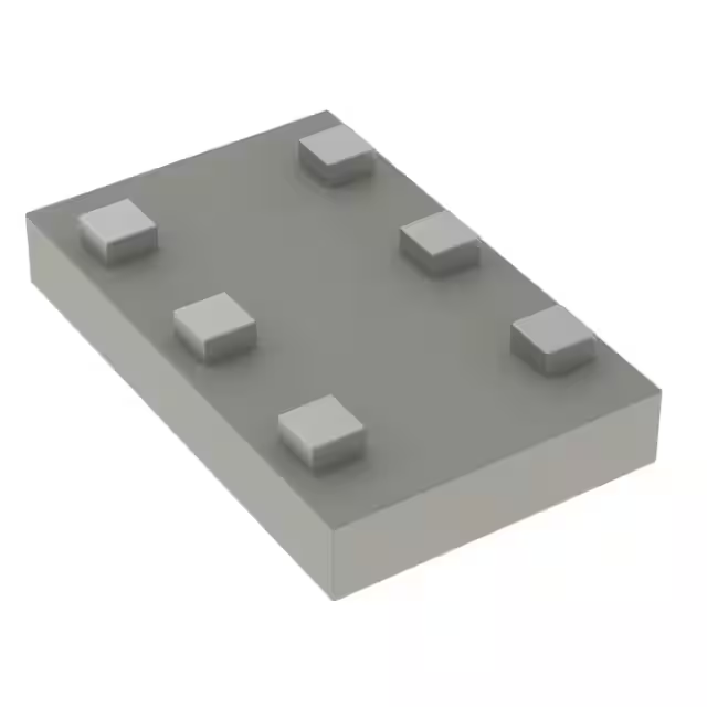
- Part No.:
- BALF-ATM-01E3
- Manufacturer:
- STMicroelectronics
- Category:
- Balun
- Package:
- 6-SMD, No Lead
- Datasheet:
-
 BALF-ATM-01E3.pdf
- Description:
- BALUN 2.4GHZ-2.5GHZ 50/50 6SMD
- Quantity:
- Payment:

- Shipping:

Inventory:1,816
Please send an inquiry. Send us your inquiry, and we will respond immediately.
Product details
Overview
BALF-ATM-01E3 from STMicroelectronics is a 2.4–2.5 GHz integrated balun transformer with built-in matching network and harmonic filter, optimized for the ATSAMR21E18 SoC. It provides 50 Ω single-ended input impedance, <1.3 dB insertion loss at 2.45 GHz, ±0.4 dB amplitude imbalance, ±9° phase imbalance, and >20 dB H2/H3 harmonic attenuation - enabling direct RF interface to 2.4 GHz ISM-band antenna systems in compact IoT nodes.
For engineers reviewing the BALF-ATM-01E3 datasheet, BALF-ATM-01E3 pinout, BALF-ATM-01E3 application, or BALF-ATM-01E3 equivalent, key selection criteria include differential impedance match to ATSAMR21E18, harmonic suppression performance at 4.9/7.35 GHz, PCB land pattern compliance with coated CSP-on-glass bumpless footprint, and thermal stability across –40 °C to +105 °C operation.
Technical Context
This monolithic balun uses ST's IPD (Integrated Passive Device) technology on a non-conductive glass substrate to achieve high RF isolation and low parasitic coupling. Its internal matching network is specifically tuned to conjugate-match the differential RF port of the ATSAMR21E18 transceiver, eliminating external discrete matching components.
The device integrates a 2nd- and 3rd-harmonic filter directly into the balun structure, delivering ≥20 dB attenuation at 4.9 GHz and 7.35 GHz without additional filtering stages. Its coated CSP-on-glass bumpless construction enables 0.425 mm typical thickness and 2.5 mm² footprint - critical for ultra-thin wearable and sensor-node PCBs.
Key Specifications
| Parameter | Value and Actual Design Meaning |
|---|---|
| Frequency Range | 2400–2500 MHz - fully covers 2.4 GHz ISM band including IEEE 802.15.4 and Bluetooth LE channels. |
| Insertion Loss | 0.91–1.3 dB at 2.45 GHz - ensures minimal RF power loss between SoC and antenna. |
| Amplitude Imbalance | ±0.4 dB at 2.45 GHz - maintains I/Q signal fidelity for robust modulation accuracy. |
| Phase Imbalance | ±9° at 2.45 GHz - preserves orthogonal signal integrity required for QPSK/OQPSK demodulation. |
| H2 Attenuation | 20–35 dB at 4.9 GHz - suppresses second harmonic to meet FCC/ETSI radiated emission limits. |
| H3 Attenuation | 20–25 dB at 7.35 GHz - prevents third-harmonic radiation from interfering with adjacent bands. |
| Input Impedance | 50 Ω single-ended - enables direct connection to standard RF test equipment and 50 Ω PCB traces. |
| Operating Temp | –40 °C to +105 °C - supports industrial and outdoor deployment without derating. |
Pinout & Package
Coated CSP-on-glass bumpless package: 2.0 × 1.25 × 0.425 mm (L × W × T), 6-pad layout with 0.2 mm pitch, no solder balls - mounted via solder paste reflow directly to PCB pads.
| Pin/Terminal | Circuit Role | Design Meaning |
|---|---|---|
| 1 (SE) | Single-ended antenna port | 50 Ω RF interface to external antenna or RF switch; requires controlled-impedance trace routing. |
| 2, 5, 6 (GND) | Ground terminals | Three dedicated ground connections ensure low-inductance return path and minimize common-mode noise. |
| 3 (BAL–) | Differential negative output | Connects to ATSAMR21E18 RFN pin; part of balanced differential pair driving SoC RF transceiver. |
| 4 (BAL+) | Differential positive output | Connects to ATSAMR21E18 RFP pin; completes matched differential interface to SoC RF port. |
Key Features
| Feature | Design Value |
|---|---|
| Monolithic IPD-on-glass | Eliminates inter-stage parasitics and improves repeatability vs. discrete LC matching networks. |
| ATSAMR21E18-optimized match | Conjugate-matched differential impedance reduces need for external tuning components and calibration. |
| Integrated H2/H3 filtering | Reduces BOM count by removing two external harmonic suppression filters in 2.4 GHz RF front-end. |
| 0.425 mm profile | Enables stacking under thin-film antennas or integration into space-constrained modules like SiP packages. |
| ECOPACK® compliant | Meets RoHS and halogen-free requirements for global industrial and consumer certifications. |
Applications
| Smart Home Sensor Node | Industrial Wireless Monitor |
|---|---|
Use Scenario: Battery-powered temperature/humidity sensor transmitting data via IEEE 802.15.4 to gateway. IC Role / Device Role / Timing Role: Balun interface between ATSAMR21E18 RF transceiver and PCB trace antenna. Use Value: Enables >10-year battery life by minimizing insertion loss and eliminating discrete matching component losses. | Use Scenario: DIN-rail mounted vibration monitor in factory environment with EMI exposure. IC Role / Device Role / Timing Role: RF front-end balun with harmonic filtering for reliable 2.4 GHz OOK/FSK transmission. Use Value: Harmonic suppression meets EN 300 328 Class 2 emission limits without added shielding or filtering. |
| Wearable Health Tracker | Asset Tracking Tag |
Use Scenario: Compact wrist-worn pulse oximeter using BLE advertising packets. IC Role / Device Role / Timing Role: Differential-to-single-ended conversion and impedance transformation for chip antenna feed. Use Value: 2.5 mm² footprint and 0.425 mm height allow integration beneath curved flexible PCB antenna layer. | Use Scenario: GPS + BLE tag attached to shipping container with intermittent 2.4 GHz beaconing. IC Role / Device Role / Timing Role: Robust RF interface supporting wide temperature range and mechanical shock. Use Value: –40 °C to +105 °C rating ensures stable RF performance during transit across climate zones. |
Availability
BALF-ATM-01E3 is available at Aetrix Electronics and suitable for smart home sensor nodes, industrial wireless monitors, wearable health trackers, and asset tracking tags requiring stable component supply and full production lifecycle support.
Supply support for BALF-ATM-01E3 includes scheduled delivery planning, volume procurement assistance, BOM continuity management, traceable sourcing, and lifecycle availability coordination for OEM customers, industrial embedded developers, connected-device designers, and electronics production programs.
Manufacturer
STMicroelectronics is a global semiconductor leader designing and manufacturing microcontrollers, analog ICs, MEMS, and power devices - serving automotive, industrial, and consumer markets with scalable, certified, and long-lifecycle solutions.
The BALF-ATM-01E3 belongs to ST's RF passive portfolio targeting ultra-compact, high-performance front-end integration for sub-1W 2.4 GHz wireless SoCs - specifically engineered to simplify design-in of Atmel/Microchip SAM R21-based systems.
FAQ
What is the recommended PCB land pattern for BALF-ATM-01E3?
The datasheet specifies a 6-pad land pattern with dimensions: pad length 0.884 mm, width 0.650 mm, spacing 0.200 mm, and solder mask opening offset by 20 µm. Use the exact footprint from Figure 12 - deviation causes solder bridging or open joints due to the bumpless CSP construction and tight 0.2 mm pitch.
Can BALF-ATM-01E3 be used with other 2.4 GHz SoCs besides ATSAMR21E18?
No - its internal matching network is customized for the ATSAMR21E18's differential port impedance and DC bias conditions. Using it with other SoCs (e.g., nRF52840 or CC2652R) results in >3 dB return loss degradation and harmonic compliance failure due to mismatched conjugate impedance.
Is reflow profile critical for this coated CSP-on-glass device?
Yes - peak reflow temperature must not exceed 260 °C for ≤10 seconds, and ramp rate must stay within 1–3 °C/s. Exceeding these violates the glass substrate's thermal expansion coefficient match, risking delamination or pad lift - confirmed by ST's assembly guidelines in Section 3.5.
Does BALF-ATM-01E3 require external DC blocking capacitors?
No - the balun is internally DC-coupled on both differential ports (BAL+/BAL–) and AC-coupled only on the single-ended side (SE). The ATSAMR21E18 RFP/RFN pins are DC-biased, so no series capacitors are needed; only the SE port requires a DC-blocking cap if feeding an active antenna or amplifier.
BALF-ATM-01E3 Specifications
- Product attributes
- Attribute value
- Manufacturer:
- STMicroelectronics
- Series:
- -
- Package/Case:
- 6-SMD, No Lead
- Packaging:
- Tape & Reel (TR)
- Product Status:
- Active
- Frequency Range:
- 2.4GHz ~ 2.5GHz
- Impedance - Unbalanced/Balanced:
- 50 / 50Ohm
- Phase Difference:
- 9°
- Insertion Loss (Max):
- 1.3dB
- Return Loss (Min):
- 15dB
- Mounting Type:
- Surface Mount
BALF-ATM-01E3 FAQ
1.How can I place an order for BALF-ATM-01E3 through Aetrix?
Please submit a Request for Quotation (RFQ) for BALF-ATM-01E3 on Aetrix. Our sales agent will provide a competitive quotation and guide you through the order confirmation once you accept the terms.
2.Are the price and stock information for BALF-ATM-01E3 reliable?
The price and inventory of BALF-ATM-01E3 are updated periodically and may fluctuate due to market conditions. Stock and pricing data are typically refreshed every 24 hours. Quotation validity for BALF-ATM-01E3 is usually 5 days.
3.What payment methods are accepted for BALF-ATM-01E3?
We accept Wire Transfer, PayPal, Credit Card, Western Union, MoneyGram, and Escrow for BALF-ATM-01E3 transactions.
Note: Certain payment methods may incur a processing fee.
4.How is shipping managed for BALF-ATM-01E3?
BALF-ATM-01E3 orders can be shipped via leading logistics carriers, including DHL, UPS, FedEx, TNT, or Registered Mail.
Once your BALF-ATM-01E3 order is processed, you will receive an email with the shipment details and tracking number.
Note: Tracking information may take up to 24 hours to appear. Express delivery typically takes 3–5 business days.
5.How can I obtain technical support or documentation for BALF-ATM-01E3?
For technical support, including BALF-ATM-01E3 datasheets, pinout diagrams, or application guidance, please contact our engineering support team. They can provide detailed documentation and assistance for your BALF-ATM-01E3 requirements.
6.How does Aetrix verify that BALF-ATM-01E3 is sourced from the original manufacturer or authorized distributors?
All BALF-ATM-01E3 products on Aetrix are procured from qualified distributors and authorized channels. Our dedicated quality assurance team conducts strict verification, including traceability checks and, if necessary, third-party testing. This ensures that BALF-ATM-01E3 meets industry standards.
7.What is the process for return or replacement of BALF-ATM-01E3?
All BALF-ATM-01E3 units undergo pre-shipment inspection (PSI). If there is an issue with BALF-ATM-01E3, returns or replacements are accepted under the following conditions:
1.Quantity discrepancies, incorrect items, or visible external defects (such as breakage or corrosion), acknowledged by Aetrix.
2.The issue is reported within 90 days of delivery.
3.The BALF-ATM-01E3 part is unused and in its original packaging.
Return procedure for BALF-ATM-01E3:
1.Submit a request within 90 days.
2.Obtain a Return Material Authorization (RMA) from Aetrix.
BALF-ATM-01E3 Tags

-
2450BL15B0100001E
Johanson Technology Inc.
-
0900BL15D0050001E
Johanson Technology Inc.
-
0900PC16J0042001E
Johanson Technology Inc.
-
2450BM15A0002001E
Johanson Technology Inc.
-
2450BM14G0011001T
Johanson Technology Inc.
-
BD0810N50100AHF
TTM Technologies, Inc.
-
1720BL15B0050001E
Johanson Technology Inc.
-
0900PC15A0036001E
Johanson Technology Inc.
-
0868BM15C0001001E
Johanson Technology Inc.
-
0915BM15A0001001E
Johanson Technology Inc.
-
HHM1776B3
TDK Corporation
-
2450BM14E0003001T
Johanson Technology Inc.
Tech Hub

A practical engineering guide to 3.3V and 5V logic compatibility, input thresholds, resistor dividers, translator ICs, MOSFET level shifting, I2C pull-ups, timing limits and power-sequencing risks.

The 74HC595 uses push-pull logic outputs, while the TPIC6B595 uses 50 V open-drain DMOS sinks for higher-power loads. This guide compares timing, current limits, 3.3 V interfacing, load wiring, thermal…

The 74HC595 converts serial data into eight stable parallel outputs. This guide covers pin functions, shift and storage timing, OE and MR behavior, drive-current limits, cascading, voltage compatibilit…

A technical comparison of level-sensitive latches and edge-triggered flip-flops, covering timing windows, setup and hold limits, master–slave operation, time borrowing, race-through, HDL inference and…

A D latch stores one bit while Enable controls when data can pass. This reference covers gate-level operation, truth tables, transparency, setup and hold timing, LE versus OE, common ICs and practical …

An SR latch stores one bit through cross-coupled feedback. This engineering reference covers NOR and NAND implementations, truth tables, forbidden-state recovery, gated operation, switch debouncing, fa…

Latch circuits retain one bit through feedback. This technical reference covers SR and D latches, truth tables, transparency, timing limits, latch-versus-flip-flop behavior, applications and common log…

An engineering guide to LED driver operation, constant-current and constant-voltage outputs, linear and switching topologies, dimming, IC selection, calculations, replacement compatibility, and fault c…

Operational amplifier guide covering op amp basics, feedback, ideal vs real op amps, common configurations, buffer circuits, offset, bias current, gain-bandwidth, slew rate, rail-to-rail limits and sel…

Jumper cables guide covering safe connection order, red and black clamp placement, final ground connection, cable gauge, length, clamp quality, copper vs CCA cables, jump starter comparison and battery…


