
 My Inquiry
 My Account


NXP Semiconductors BB148,135
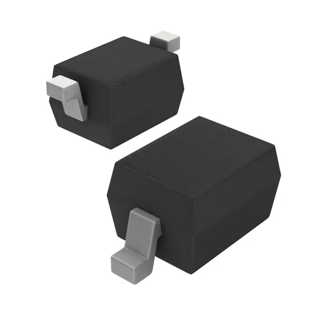
- Part No.:
- BB148,135
- Manufacturer:
- NXP Semiconductors
- Package:
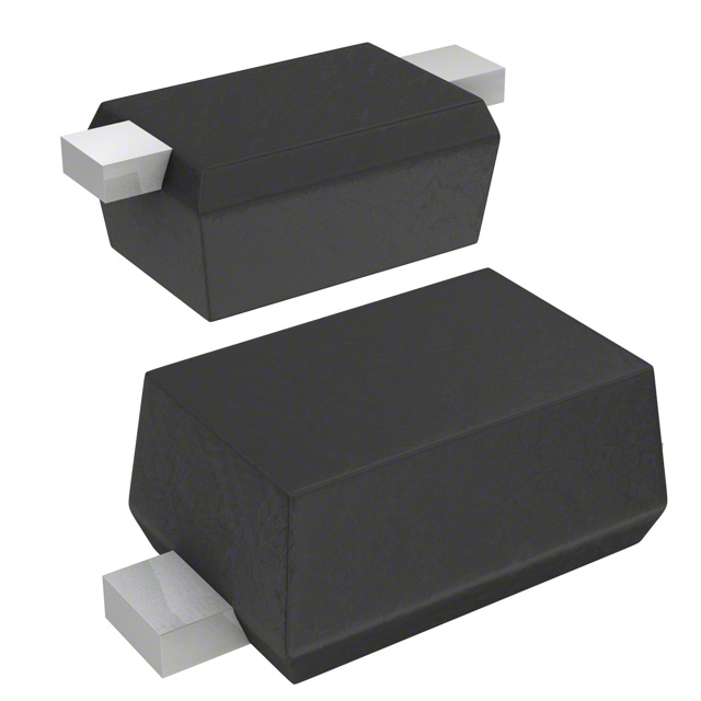
- SC-76, SOD-323
- Datasheet:
-
 BB148,135.pdf
- Description:
- DIODE VHF VAR CAP 30V SOD323
- Quantity:
- Payment:

- Shipping:

Inventory:8,833
Please send an inquiry. Send us your inquiry, and we will respond immediately.
Product details
Overview
BB148 from NXP Semiconductors is a VHF variable capacitance diode (varactor) fabricated in planar technology and housed in an SOD323 (SC-76) surface-mount package. It delivers 2.6 pF capacitance at 28 V reverse bias, a 15:1 capacitance ratio (Cd(1V)/Cd(28V)), and ≤2 % gliding matching across 10-diode sequences - enabling precise tuning in high-frequency TV tuners and VCOs up to 460 MHz.
For engineers reviewing the BB148 datasheet, BB148 pinout, BB148 application, or BB148 equivalent, this page provides verified specifications including reverse voltage rating (30 V), series resistance (≤0.9 Ω at 100 MHz), junction temperature range (−55 °C to +125 °C), and matched-group delivery options for RF calibration-critical designs.
Technical Context
The BB148 operates as a reverse-biased junction capacitor whose depletion width-and thus capacitance-varies nonlinearly with applied DC voltage. Its Cd(1V) = 36.8–41.8 pF and Cd(28V) = 2.4–2.75 pF enable wide-range VHF tuning while maintaining low series resistance (≤0.9 Ω) for minimal Q degradation in resonant tank circuits.
Designed for high-matching accuracy, the BB148 uses Direct Matching Assembly (DMA) and gliding matching to achieve ≤2 % capacitance deviation across sequential units, supporting production-level consistency in multi-stage VCOs and band-selective TV tuner modules without individual calibration.
Key Specifications
| Parameter | Value and Actual Design Meaning |
|---|---|
| Capacitance @ 1 V | 36.8–41.8 pF - sets minimum resonant frequency and tuning range lower bound in VCO tanks |
| Capacitance @ 28 V | 2.4–2.75 pF - defines maximum resonant frequency and high-end tuning limit |
| Capacitance Ratio | 14.5–15 - determines total frequency tuning bandwidth (e.g., ~4× f₀ span in LC oscillators) |
| Series Resistance | ≤0.9 Ω @ 100 MHz, Cd = 12 pF - preserves Q-factor >100 in 100–460 MHz VHF resonators |
| Reverse Voltage Rating | 30 V - supports standard 28 V VCO bias rails with 2 V safety margin |
| Matching Tolerance | ≤2 % over 10-diode sequence - enables drop-in replacement in matched-pair VCO trim networks |
Pinout & Package
SOD323 (SC-76) plastic surface-mounted package: 2-terminal, 1.35 × 0.85 × 0.45 mm body, cathode marked by bar on top surface.
| Pin/Terminal | Circuit Role | Design Meaning |
|---|---|---|
| 1 | Cathode | Connected to DC bias rail; reverse-bias polarity reference for varactor operation |
| 2 | Anode | AC signal node in tuned circuit; grounded or AC-coupled in VCO tank configurations |
Key Features
| Feature | Design Value |
|---|---|
| Excellent linearity | Capacitance vs. voltage curve optimized for monotonic, predictable tuning slope in 1–28 V range |
| DMA matching to 1 % | Factory-trimmed unit-to-unit capacitance variation ≤1 % within matched groups for dual-VCO or I/Q tuning |
| Low series resistance | ≤0.9 Ω minimizes insertion loss and phase noise degradation in high-Q VHF oscillator tanks |
| VHF-optimized construction | Planar die geometry and SOD323 leadframe reduce parasitic inductance for stable operation up to 460 MHz |
Applications
| TV Tuner Band B | Voltage-Controlled Oscillator |
|---|---|
|
Use Scenario: Channel selection in analog/digital VHF television receivers operating in Band B (47–230 MHz). IC Role / Device Role / Timing Role: Varactor diode in LC tank circuit of front-end tuner, modulated by tuning voltage to shift resonant frequency. Use Value: 15:1 capacitance ratio enables full-band coverage with single-tank design; ≤2 % matching ensures consistent channel spacing across production units. |
Use Scenario: Frequency tuning element in monolithic VCOs for wireless transceivers and test equipment. IC Role / Device Role / Timing Role: Voltage-variable reactance controlling oscillation frequency in Colpitts or Clapp topology. Use Value: Low rs (≤0.9 Ω) maintains phase noise performance below −110 dBc/Hz at 100 kHz offset; SOD323 footprint allows dense RF layout. |
| RF Filter Tuning | FM Radio Front-End |
|
Use Scenario: Adaptive bandpass filtering in software-defined radio (SDR) receivers requiring dynamic IF center frequency adjustment. IC Role / Device Role / Timing Role: Tuning capacitor in switched-capacitor or active LC filter stages. Use Value: Gliding matching ≤2 % ensures repeatable filter response across multiple channels without per-unit calibration. |
Use Scenario: Local oscillator tuning in FM broadcast band (87.5–108 MHz) receivers. IC Role / Device Role / Timing Role: Varactor in VHF oscillator stage generating LO signal for mixer downconversion. Use Value: Cd(1V)/Cd(28V) = 15 supports full-band FM coverage with <±10 kHz frequency error; SOD323 enables compact PCB layout. |
Equivalent & Alternatives
The following parts are listed as comparable options for similar varactor diode applications.
| Alternative Part | Technical Difference | Application Difference | Selection Advice |
|---|---|---|---|
| BB158 | Unmatched version of same die; identical Cd(1V), Cd(28V), rs, and VR specs but no DMA or gliding matching | Lacks guaranteed unit-to-unit capacitance consistency; suitable for non-critical tuning where calibration is performed per unit | Select BB158 when cost sensitivity outweighs matching requirements and system-level trimming is feasible |
| SMV1232-011 | Higher Cd(1V) = 56 pF, lower ratio = 10.5, rs = 1.2 Ω; SOD-523 package (smaller, 1.2 × 0.8 mm) | Better low-frequency tuning range but reduced VHF bandwidth; higher rs increases phase noise in 200+ MHz VCOs | Choose SMV1232-011 only if wider low-end capacitance is required and 460 MHz operation is not needed |
Compared with BB148, BB158 offers identical electrical specs without matching assurance, while SMV1232-011 trades VHF linearity and low rs for higher base capacitance - making BB148 optimal for production-grade 460 MHz TV tuners and low-phase-noise VCOs demanding matched performance.
Availability
BB148 is available at Aetrix Electronics and suitable for VHF television tuners, voltage-controlled oscillators, RF filter tuning, and FM radio front-ends requiring stable component supply and factory-matched varactor performance.
Supply support for BB148 includes scheduled delivery planning, volume procurement assistance, BOM continuity management, traceable sourcing, and lifecycle availability coordination for OEM customers, industrial embedded developers, connected-device designers, and electronics production programs.
Manufacturer
NXP Semiconductors is a global semiconductor company headquartered in Eindhoven, Netherlands, specializing in secure connectivity solutions for automotive, industrial, and consumer applications.
The BB148 belongs to NXP's RF varactor diode product line, engineered specifically for high-precision, high-frequency electronic tuning in broadcast and communications systems up to 460 MHz.
FAQ
What is the maximum reverse voltage rating for BB148?
The BB148 has an absolute maximum reverse voltage rating of 30 V, as defined in IEC 60134 limiting values. Operation at 28 V is typical in VCO bias networks, providing a 2 V safety margin against transient overvoltage. Exceeding 30 V risks permanent junction damage and irreversible capacitance drift in the BB148.
How does BB148 achieve its 15:1 capacitance ratio?
The BB148 achieves a Cd(1V)/Cd(28V) ratio of 14.5–15 through controlled doping profile and planar junction geometry, yielding 36.8–41.8 pF at 1 V and 2.4–2.75 pF at 28 V reverse bias. This ratio is measured at 1 MHz and 25 °C, and remains stable across the −55 °C to +125 °C junction temperature range specified for the BB148.
Is BB148 suitable for automotive applications?
No - the BB148 is not automotive-qualified. NXP explicitly states that unless a product data sheet declares automotive qualification, the device is unsuitable for safety-critical or life-support systems. The BB148 data sheet contains no AEC-Q200 stress test results or automotive temperature grade (e.g., Grade 1 or 2), and its specification applies only to commercial/industrial use.
What does the marking code 'P8' indicate on BB148?
The marking code 'P8' laser-etched on the BB148 top surface identifies the device as the BB148 type in SOD323 package per NXP's ordering information table. It is not a date code or lot identifier; 'P8' is the standardized marking assigned exclusively to BB148 units, distinguishing them from BB158 (unmatched variant) and other varactors in the same package family.
Can BB148 be used in place of BB158?
Yes - BB148 and BB158 share identical electrical specifications (Cd, rs, VR, IR) and mechanical form factor, but BB148 adds Direct Matching Assembly (DMA) and gliding matching (≤2 %). Substituting BB148 for BB158 improves tuning consistency in multi-unit systems; substituting BB158 for BB148 removes matching assurance but retains full functional compatibility in the BB148 circuit design.
BB148,135 Specifications
- Product attributes
- Attribute value
- Manufacturer:
- NXP Semiconductors
- Series:
- -
- Package/Case:
- SC-76, SOD-323
- Packaging:
- Tape & Reel (TR)
- Product Status:
- Obsolete
- Capacitance @ Vr, F:
- 2.75pF @ 28V, 1MHz
- Capacitance Ratio:
- 15.0
- Capacitance Ratio Condition:
- C1/C28
- Voltage - Peak Reverse (Max):
- 30 V
- Diode Type:
- Single
- Q @ Vr, F:
- -
- Operating Temperature:
- -55°C ~ 125°C (TJ)
- Grade:
- -
- Qualification:
- -
- Mounting Type:
- Surface Mount
- Supplier Device Package:
- SOD-323
BB148,135 FAQ
1.How can I place an order for BB148,135 through Aetrix?
Please submit a Request for Quotation (RFQ) for BB148,135 on Aetrix. Our sales agent will provide a competitive quotation and guide you through the order confirmation once you accept the terms.
2.Are the price and stock information for BB148,135 reliable?
The price and inventory of BB148,135 are updated periodically and may fluctuate due to market conditions. Stock and pricing data are typically refreshed every 24 hours. Quotation validity for BB148,135 is usually 5 days.
3.What payment methods are accepted for BB148,135?
We accept Wire Transfer, PayPal, Credit Card, Western Union, MoneyGram, and Escrow for BB148,135 transactions.
Note: Certain payment methods may incur a processing fee.
4.How is shipping managed for BB148,135?
BB148,135 orders can be shipped via leading logistics carriers, including DHL, UPS, FedEx, TNT, or Registered Mail.
Once your BB148,135 order is processed, you will receive an email with the shipment details and tracking number.
Note: Tracking information may take up to 24 hours to appear. Express delivery typically takes 3–5 business days.
5.How can I obtain technical support or documentation for BB148,135?
For technical support, including BB148,135 datasheets, pinout diagrams, or application guidance, please contact our engineering support team. They can provide detailed documentation and assistance for your BB148,135 requirements.
6.How does Aetrix verify that BB148,135 is sourced from the original manufacturer or authorized distributors?
All BB148,135 products on Aetrix are procured from qualified distributors and authorized channels. Our dedicated quality assurance team conducts strict verification, including traceability checks and, if necessary, third-party testing. This ensures that BB148,135 meets industry standards.
7.What is the process for return or replacement of BB148,135?
All BB148,135 units undergo pre-shipment inspection (PSI). If there is an issue with BB148,135, returns or replacements are accepted under the following conditions:
1.Quantity discrepancies, incorrect items, or visible external defects (such as breakage or corrosion), acknowledged by Aetrix.
2.The issue is reported within 90 days of delivery.
3.The BB148,135 part is unused and in its original packaging.
Return procedure for BB148,135:
1.Submit a request within 90 days.
2.Obtain a Return Material Authorization (RMA) from Aetrix.
BB148,135 Tags
-
BBY5702VH6327XTSA1
Infineon Technologies
-
BBY5602VH6327XTSA1
Infineon Technologies
-
SMV1405-040LF
Skyworks Solutions Inc.
-
BBY6502VH6327XTSA1
Infineon Technologies
-
BBY6602VH6327XTSA1
Infineon Technologies
-
BBY5802VH6327XTSA1
Infineon Technologies
.jpg)
-
BB175X
NXP Semiconductors
-
SMV1430-040LF
Skyworks Solutions Inc.
-
SMV1273-079LF
Skyworks Solutions Inc.
-
SMV1255-079LF
Skyworks Solutions Inc.
-
SMV1213-079LF
Skyworks Solutions Inc.
-
SMV1247-079LF
Skyworks Solutions Inc.
Tech Hub

A practical engineering guide to 3.3V and 5V logic compatibility, input thresholds, resistor dividers, translator ICs, MOSFET level shifting, I2C pull-ups, timing limits and power-sequencing risks.

The 74HC595 uses push-pull logic outputs, while the TPIC6B595 uses 50 V open-drain DMOS sinks for higher-power loads. This guide compares timing, current limits, 3.3 V interfacing, load wiring, thermal…

The 74HC595 converts serial data into eight stable parallel outputs. This guide covers pin functions, shift and storage timing, OE and MR behavior, drive-current limits, cascading, voltage compatibilit…

A technical comparison of level-sensitive latches and edge-triggered flip-flops, covering timing windows, setup and hold limits, master–slave operation, time borrowing, race-through, HDL inference and…

A D latch stores one bit while Enable controls when data can pass. This reference covers gate-level operation, truth tables, transparency, setup and hold timing, LE versus OE, common ICs and practical …

An SR latch stores one bit through cross-coupled feedback. This engineering reference covers NOR and NAND implementations, truth tables, forbidden-state recovery, gated operation, switch debouncing, fa…

Latch circuits retain one bit through feedback. This technical reference covers SR and D latches, truth tables, transparency, timing limits, latch-versus-flip-flop behavior, applications and common log…

An engineering guide to LED driver operation, constant-current and constant-voltage outputs, linear and switching topologies, dimming, IC selection, calculations, replacement compatibility, and fault c…

Operational amplifier guide covering op amp basics, feedback, ideal vs real op amps, common configurations, buffer circuits, offset, bias current, gain-bandwidth, slew rate, rail-to-rail limits and sel…

Jumper cables guide covering safe connection order, red and black clamp placement, final ground connection, cable gauge, length, clamp quality, copper vs CCA cables, jump starter comparison and battery…


