
 My Inquiry
 My Account


NXP Semiconductors BF1212,215
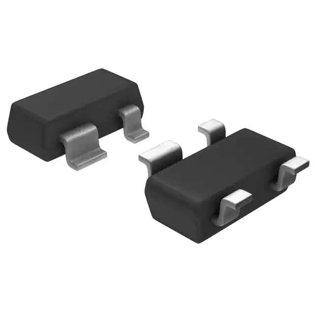
- Part No.:
- BF1212,215
- Manufacturer:
- NXP Semiconductors
- Category:
- Single FETs, MOSFETs
- Package:
- TO-253-4, TO-253AA
- Datasheet:
-
 BF1212,215.pdf
- Description:
- RF MOSFET 5V SOT143B
- Quantity:
- Payment:

- Shipping:

Inventory:7,948
Please send an inquiry. Send us your inquiry, and we will respond immediately.
Product details
Overview
BF1212 from NXP Semiconductors is an enhancement-type N-channel dual-gate MOSFET designed for low-noise, gain-controlled VHF/UHF amplification in 5 V digital and analog TV tuners. It features a SOT143B package, 33 mS typical forward transfer admittance (|yfs|), 1.7 pF input capacitance at gate 1 (Cig1-ss), and 1.1 dB noise figure at 800 MHz.
For engineers reviewing the BF1212 datasheet, BF1212 pinout, BF1212 application, or BF1212 equivalent, this device is selected for high-yfs/Cig1 ratio, internal self-biasing for AGC stability, and cross-modulation performance exceeding 100 dBµV at 40 dB AGC in tuner front-end designs.
Technical Context
The BF1212 integrates source-substrate interconnection and built-in protection diodes between both gates and source to suppress voltage surges. Its dual-gate architecture enables independent control of gain (via gate 2) and signal input (via gate 1), supporting precise AGC implementation without external bias networks.
It operates as a low-noise amplifier with DC stabilization via partial internal self-biasing, ensuring consistent cross-modulation performance across AGC ranges. The device is characterized at VDS = 5 V, ID = 12 mA, and VG2-S = 4 V, with noise optimization up to 800 MHz and power gain of 25 dB at that frequency.
Key Specifications
| Parameter | Value and Actual Design Meaning |
|---|---|
| VDS | 6 V maximum - sets safe operating voltage ceiling for tuner supply rails and transient immunity. |
| |yfs| | 33 mS typical - delivers high transconductance for strong small-signal gain with minimal input loading. |
| Cig1-ss | 1.7 pF typical - low gate-1 input capacitance preserves Q-factor and tuning range in VHF/UHF tank circuits. |
| F | 1.1 dB typical at 800 MHz - enables high-fidelity signal amplification with minimal added noise in UHF band reception. |
| Xmod | 100–104 dBµV at 40 dB AGC - ensures robust suppression of adjacent-channel interference under strong-signal conditions. |
| Ptot | 180 mW maximum - defines thermal envelope for surface-mount operation on compact tuner PCBs. |
| Tj | 150 °C maximum - establishes junction temperature limit for reliability under continuous 5 V tuner operation. |
Pinout & Package
BF1212 is housed in a plastic surface-mounted SOT143B package (4 leads), with dimensions per outline MSB014: D = 2.8–3.0 mm, E = 1.2–1.4 mm, body height A = 0.9–1.1 mm, and lead pitch e = 1.9 mm.
| Pin/Terminal | Circuit Role | Design Meaning |
|---|---|---|
| 1 | Source | Common reference node for both gates and drain; internally connected to substrate for stable channel formation. |
| 2 | Drain | Output terminal carrying amplified RF current; requires impedance-matched output network for gain and stability. |
| 3 | Gate 2 | AGC control input; biases channel conductance to adjust gain dynamically without affecting gate-1 signal path. |
| 4 | Gate 1 | RF signal input terminal; isolated from gate 2 by physical structure to minimize feedthrough and preserve linearity. |
Key Features
| Feature | Design Value |
|---|---|
| Dual-gate architecture with source-substrate tie | Enables independent RF input (G1) and gain control (G2) while stabilizing threshold voltage against substrate potential shifts. |
| Integrated gate-source protection diodes | Prevents gate oxide damage from ESD or tuner-tuning transient spikes without requiring external clamping components. |
| Partially internal self-biasing circuit | Reduces external component count for DC stabilization and maintains cross-modulation performance across AGC range. |
| High |yfs| / Cig1-ss ratio | Delivers superior gain-per-capacitance in VHF/UHF bands, improving selectivity and reducing matching network complexity. |
| Low-frequency noise optimization | Supports clean baseband extraction in analog TV demodulation paths where 1/f noise directly impacts picture quality. |
Applications
| TV Tuner Front-End Amplifier | Digital Terrestrial Receiver LNA |
|---|---|
Use Scenario: Amplifying weak VHF/UHF broadcast signals before mixer stage in analog/digital TV tuners operating from 5 V supply. IC Role / Device Role / Timing Role: Low-noise, gain-controlled RF amplifier with dual-gate AGC interface and integrated surge protection. Use Value: Achieves 1.1 dB noise figure at 800 MHz and >100 dBµV cross-modulation rejection under 40 dB AGC, enabling reliable reception in urban multipath environments. |
Use Scenario: First-stage amplification in DVB-T/T2 receiver modules where compact size and low power are critical. IC Role / Device Role / Timing Role: High-yfs discrete MOSFET providing adjustable gain and low input capacitance for wideband antenna matching. Use Value: 1.7 pF Cig1-ss minimizes detuning of printed antenna traces; 180 mW Ptot allows operation within thermal limits on dense PCB layouts. |
| Analog TV IF Gain Control Stage | UHF Bandwidth-Extension Amplifier |
Use Scenario: Variable-gain amplification in analog TV intermediate frequency (IF) chains requiring stable DC bias and low distortion. IC Role / Device Role / Timing Role: Dual-gate MOSFET configured with gate 2 as AGC voltage input and gate 1 as IF signal input. Use Value: Internal self-biasing ensures consistent gain vs. temperature and supply variation, reducing need for calibration in mass-produced sets. |
Use Scenario: Extending usable bandwidth beyond 500 MHz in legacy UHF tuners upgraded for higher-channel-count digital services. IC Role / Device Role / Timing Role: Discrete RF transistor optimized for 800 MHz operation with 25 dB power gain and 1.1 dB noise figure. Use Value: Maintains >20 dB gain up to 1 GHz while holding F ≤ 1.8 dB, enabling full UHF spectrum coverage without cascaded stages. |
Equivalent & Alternatives
The following parts are listed as comparable options for similar dual-gate MOSFET amplifier applications.
| Alternative Part | Technical Difference | Application Difference | Selection Advice |
|---|---|---|---|
| BF1212R | SOT143R package with reverse pinning (pin 3 = gate 1, pin 4 = gate 2); identical electrical specs. | Requires PCB layout revision due to swapped gate terminals; same RF performance and AGC behavior. | Select when board space constraints favor SOT143R footprint or when sourcing continuity requires alternate pinout variant. |
| BF1212WR | SOT343R package (smaller 2.2 × 1.35 mm); Rth j-s = 155 K/W vs. 185 K/W for BF1212; same electrical parameters. | Better thermal resistance supports higher ambient operation in compact tuners; requires updated land pattern. | Choose for space-constrained designs needing improved thermal performance without changing circuit topology. |
Compared with BF1212R and BF1212WR, the BF1212 offers the original SOT143B footprint with standard pinout-ideal for legacy tuner designs where layout reuse and supply chain consistency are prioritized over miniaturization or thermal margin.
Availability
BF1212 is available at Aetrix Electronics and suitable for VHF/UHF TV tuner front-ends, digital terrestrial receiver LNAs, and analog TV IF gain control stages requiring stable component supply and long-term obsolescence management.
Supply support for BF1212 includes scheduled delivery planning, volume procurement assistance, BOM continuity management, traceable sourcing, and lifecycle availability coordination for OEM customers, industrial embedded developers, connected-device designers, and electronics production programs.
Manufacturer
NXP Semiconductors is a global semiconductor company specializing in high-performance RF, analog, and mixed-signal solutions for consumer, industrial, and communications markets.
The BF1212 belongs to NXP's legacy discrete RF transistor family, engineered specifically for low-noise, gain-stable amplification in 5 V television tuner applications across VHF and UHF bands.
FAQ
What is the maximum drain-source voltage rating for BF1212?
The BF1212 has a maximum drain-source voltage (VDS) rating of 6 V, as specified in the Absolute Maximum Ratings table. This limit ensures safe operation under normal 5 V tuner supply conditions and transient voltage spikes. Exceeding 6 V risks permanent breakdown of the channel region. The BF1212 datasheet confirms this value applies to all operating temperatures and is validated per IEC 60134 limiting values.
Does BF1212 require external bias components for basic operation?
The BF1212 incorporates a partly internal self-biasing circuit, reducing dependency on external resistors for DC stabilization-especially during AGC modulation. However, gate 1 still requires a DC return path (e.g., 150 kΩ resistor to VGG = 5 V, per Fig.21 test setup) to establish proper operating point. Gate 2 is typically driven by an AGC voltage source. No external source bypassing is needed due to internal substrate-source connection.
How does BF1212 achieve low cross-modulation in TV tuners?
The BF1212 achieves low cross-modulation (Xmod ≥100 dBµV at 40 dB AGC) through its dual-gate structure and internal self-biasing, which maintains linear channel conductance under varying AGC voltages. The gate-2 controlled transconductance shift occurs with minimal distortion, and integrated gate-source diodes prevent gate voltage runaway during strong interferers. Measured data in the datasheet confirms this performance at 50/60 MHz two-tone tests.
What is the thermal resistance from junction to soldering point for BF1212?
The BF1212 has a thermal resistance from junction to soldering point (Rth j-s) of 185 K/W, as stated in the Thermal Characteristics section. This value assumes Ts ≤ 116 °C and applies to the SOT143B package. It determines allowable power dissipation (180 mW max) under given board copper area and airflow; derating curves (Fig.4) show linear reduction above Ts = 116 °C.
Can BF1212 be used in 800 MHz UHF applications?
Yes, the BF1212 is characterized and specified for 800 MHz operation: noise figure is 1.1 dB typical, power gain is 25 dB, and cross-modulation remains ≥100 dBµV at that frequency. The datasheet provides scattering parameters (Table 1) and noise data (Table 2) up to 1000 MHz, confirming stable S-parameter behavior and low Fmin across the UHF band. Its 1.7 pF Cig1-ss also supports broadband matching.
BF1212,215 Specifications
- Product attributes
- Attribute value
- Manufacturer:
- NXP Semiconductors
- Series:
- -
- Package/Case:
- TO-253-4, TO-253AA
- Packaging:
- Tape & Reel (TR)
- Product Status:
- Obsolete
- Technology:
- MOSFET (Metal Oxide)
- Configuration:
- N-Channel Dual Gate
- Frequency:
- 400MHz
- Gain:
- 30dB
- Voltage - Test:
- 5 V
- Current Rating (Amps):
- 30mA
- Noise Figure:
- 0.9dB
- Current - Test:
- 12 mA
- Power - Output:
- -
- Voltage - Rated:
- 6 V
- Grade:
- -
- Qualification:
- -
- Mounting Type:
- Surface Mount
- Supplier Device Package:
- SOT-143B
BF1212,215 FAQ
1.How can I place an order for BF1212,215 through Aetrix?
Please submit a Request for Quotation (RFQ) for BF1212,215 on Aetrix. Our sales agent will provide a competitive quotation and guide you through the order confirmation once you accept the terms.
2.Are the price and stock information for BF1212,215 reliable?
The price and inventory of BF1212,215 are updated periodically and may fluctuate due to market conditions. Stock and pricing data are typically refreshed every 24 hours. Quotation validity for BF1212,215 is usually 5 days.
3.What payment methods are accepted for BF1212,215?
We accept Wire Transfer, PayPal, Credit Card, Western Union, MoneyGram, and Escrow for BF1212,215 transactions.
Note: Certain payment methods may incur a processing fee.
4.How is shipping managed for BF1212,215?
BF1212,215 orders can be shipped via leading logistics carriers, including DHL, UPS, FedEx, TNT, or Registered Mail.
Once your BF1212,215 order is processed, you will receive an email with the shipment details and tracking number.
Note: Tracking information may take up to 24 hours to appear. Express delivery typically takes 3–5 business days.
5.How can I obtain technical support or documentation for BF1212,215?
For technical support, including BF1212,215 datasheets, pinout diagrams, or application guidance, please contact our engineering support team. They can provide detailed documentation and assistance for your BF1212,215 requirements.
6.How does Aetrix verify that BF1212,215 is sourced from the original manufacturer or authorized distributors?
All BF1212,215 products on Aetrix are procured from qualified distributors and authorized channels. Our dedicated quality assurance team conducts strict verification, including traceability checks and, if necessary, third-party testing. This ensures that BF1212,215 meets industry standards.
7.What is the process for return or replacement of BF1212,215?
All BF1212,215 units undergo pre-shipment inspection (PSI). If there is an issue with BF1212,215, returns or replacements are accepted under the following conditions:
1.Quantity discrepancies, incorrect items, or visible external defects (such as breakage or corrosion), acknowledged by Aetrix.
2.The issue is reported within 90 days of delivery.
3.The BF1212,215 part is unused and in its original packaging.
Return procedure for BF1212,215:
1.Submit a request within 90 days.
2.Obtain a Return Material Authorization (RMA) from Aetrix.
BF1212,215 Tags
-
3SK294(TE85L,F)
Toshiba Semiconductor and Storage

-
SAV-551+
Mini-Circuits

-
TAV2-501+
Mini-Circuits
-
CE3514M4-C2
CEL
-
AFT05MS004NT1
NXP USA Inc.
-
SAV-541+
Mini-Circuits
-
CE3512K2-C1
CEL
-
AFM907NT1
NXP Semiconductors
-
SKY65050-372LF
Skyworks Solutions Inc.
-
CE3520K3-C1
CEL
-
AFT09MS007NT1
NXP USA Inc.
-
AFT09MS015NT1
NXP USA Inc.
Tech Hub

A practical engineering guide to 3.3V and 5V logic compatibility, input thresholds, resistor dividers, translator ICs, MOSFET level shifting, I2C pull-ups, timing limits and power-sequencing risks.

The 74HC595 uses push-pull logic outputs, while the TPIC6B595 uses 50 V open-drain DMOS sinks for higher-power loads. This guide compares timing, current limits, 3.3 V interfacing, load wiring, thermal…

The 74HC595 converts serial data into eight stable parallel outputs. This guide covers pin functions, shift and storage timing, OE and MR behavior, drive-current limits, cascading, voltage compatibilit…

A technical comparison of level-sensitive latches and edge-triggered flip-flops, covering timing windows, setup and hold limits, master–slave operation, time borrowing, race-through, HDL inference and…

A D latch stores one bit while Enable controls when data can pass. This reference covers gate-level operation, truth tables, transparency, setup and hold timing, LE versus OE, common ICs and practical …

An SR latch stores one bit through cross-coupled feedback. This engineering reference covers NOR and NAND implementations, truth tables, forbidden-state recovery, gated operation, switch debouncing, fa…

Latch circuits retain one bit through feedback. This technical reference covers SR and D latches, truth tables, transparency, timing limits, latch-versus-flip-flop behavior, applications and common log…

An engineering guide to LED driver operation, constant-current and constant-voltage outputs, linear and switching topologies, dimming, IC selection, calculations, replacement compatibility, and fault c…

Operational amplifier guide covering op amp basics, feedback, ideal vs real op amps, common configurations, buffer circuits, offset, bias current, gain-bandwidth, slew rate, rail-to-rail limits and sel…

Jumper cables guide covering safe connection order, red and black clamp placement, final ground connection, cable gauge, length, clamp quality, copper vs CCA cables, jump starter comparison and battery…


