
 My Inquiry
 My Account


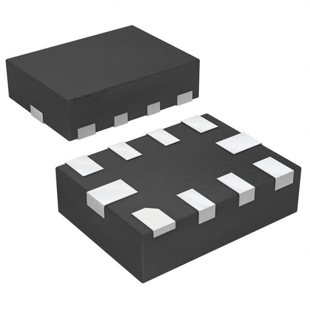
Texas Instruments BQ24392QRSERQ1
- Part No.:
- BQ24392QRSERQ1
- Manufacturer:
- Texas Instruments
- Category:
- Battery Management
- Package:
- 10-UFQFN
- Datasheet:
-
 BQ24392QRSERQ1.pdf
- Description:
- IC BATT MFUNC USB 10UQFN
- Quantity:
- Payment:

- Shipping:

Inventory:5,958
Please send an inquiry. Send us your inquiry, and we will respond immediately.
Product details
Overview
BQ24392QRSERQ1 from Texas Instruments is an automotive-qualified dual SPST USB 2.0 high-speed isolation switch with integrated BCv1.2/Apple/TomTom charger detection, operating across –40°C to 125°C ambient, supporting 480-Mbps data transfer, 28-V VBUS tolerance, and ±8-kV IEC 61000-4-2 ESD protection on DP/DM_CON pins - deployed in rear-seat entertainment and GPS systems for automatic charging path selection and data path enablement.
For engineers reviewing the BQ24392QRSERQ1 datasheet, BQ24392QRSERQ1 pinout, BQ24392QRSERQ1 application, or BQ24392QRSERQ1 equivalent, key selection criteria include USB 2.0 signal integrity (1 GHz bandwidth, <2.4 Ω RON flatness), automotive-grade thermal performance (RθJA = 167.7°C/W), dead-battery provision timer (32–45 min), and GPIO-driven system control via CHG_DET, CHG_AL_N, and SW_OPEN outputs.
Technical Context
The BQ24392QRSERQ1 implements a two-stage detection architecture: first, Data Contact Detection (DCD) with 600-ms timeout per BCv1.2, followed by primary (DCP/SDP/CDP) and secondary (Apple/TomTom/non-compliant) classification using voltage-level sensing on DP_CON/DM_CON. It operates without external power - powered solely from VBUS - and uses GOOD_BAT input to gate USB switch activation and trigger Dead Battery Provision (DBP) logic.
Its dual-channel analog switch supports independent D+/D− paths with matched ON-resistance (ΔRON ≤ 0.5 Ω), low off-capacitance (CO(OFF) = 10 pF), high isolation (–26 dB @ 240 MHz), and minimal crosstalk (–30.5 dB), enabling clean 480-Mbps eye diagrams while maintaining full USB 2.0 compliance during charging detection cycles.
Key Specifications
| Parameter | Value and Actual Design Meaning |
|---|---|
| VBUS Range | –2 V to 28 V - eliminates need for external overvoltage protection in automotive USB ports |
| USB Data Rate | 480 Mbps - fully compliant with USB 2.0 High-Speed signaling |
| Bandwidth | 1 GHz - preserves signal integrity for full-speed USB 2.0 eye diagram performance |
| RON (per channel) | 6–8 Ω - ensures minimal insertion loss and voltage drop in data path |
| RON Flatness | 1.1–2.4 Ω - maintains differential signal balance across operating voltage range |
| ESD (DP/DM_CON) | ±8 kV contact discharge (IEC 61000-4-2) - meets automotive system-level ESD robustness requirements |
| Operating Temp | –40°C to +125°C ambient - qualified per AEC-Q100 Grade 1 for under-hood and infotainment use |
Pinout & Package
Package: UQFN-10 (RSE), 2.05 mm × 1.55 mm, 0.4-mm pitch, wettable flank - optimized for automated optical inspection (AOI) and automotive reflow profiles (MSL Level-3, 260°C peak).
| Pin/Terminal | Circuit Role | Design Meaning |
|---|---|---|
| 1. SW_OPEN | Open-drain status indicator | LOW = USB switch closed (data path enabled); HIGH-Z = open - requires 10-kΩ pull-up for host monitoring |
| 2. DM_HOST | Host-side D− signal | I/O port connected to USB transceiver; supports 0–3.6 V analog swing with 11-pF on-capacitance |
| 3. DP_HOST | Host-side D+ signal | I/O port connected to USB transceiver; matched with DM_HOST for differential integrity |
| 4. CHG_AL_N | Open-drain charge-allow flag | LOW = charging permitted (100 mA or full current); HIGH-Z = disabled - used with GOOD_BAT to enforce safety logic |
| 5. GOOD_BAT | Input battery-status signal | HIGH = healthy battery (enables SDP/CDP switch closure); LOW triggers DBP timer and blocks charging |
| 6. GND | Ground reference | Not internally connected - must be externally tied to system ground for ESD and thermal performance |
| 7. DP_CON | Connector-side D+ signal | Direct interface to micro/mini-USB port; rated for ±8-kV IEC ESD and 28-V VBUS transients |
| 8. DM_CON | Connector-side D− signal | Differential partner to DP_CON; voltage-level sensing enables Apple/TomTom charger identification |
| 9. VBUS | Power input & detection source | Supplies device; >3.5 V threshold initiates detection; clamps CHG_DET output at 7 V if >7 V |
| 10. CHG_DET | Push-pull charger-detect flag | HIGH = charger detected (DCP/SDP/CDP/Apple/TomTom); drives host interrupt or state machine directly |
Key Features
| Feature | Design Value |
|---|---|
| AEC-Q100 Grade 1 qualification | Validated for –40°C to +125°C operation with HBM ±4 kV and CDM ±1.5 kV (corner pins ±8 kV) |
| BCv1.2 + proprietary charger detection | Identifies DCP, SDP, CDP, Apple, TomTom, and non-compliant chargers within ≤600 ms |
| Dead Battery Provision (DBP) timer | 32–45 minute timeout disables charging when GOOD_BAT remains LOW - prevents deep-discharge damage |
| USB 2.0 signal integrity preservation | 1 GHz bandwidth, –26 dB isolation, –30.5 dB crosstalk, and <2.4 Ω RON flatness maintain 480-Mbps eye compliance |
| VVBUS-powered architecture | No external bias required - simplifies layout and reduces BOM count in space-constrained automotive modules |
Applications
| Rear-Seat Entertainment Systems | Automotive GPS Navigation Units |
|---|---|
Use Scenario: Micro-USB port in vehicle seatback enables tablet charging and media sync while driving. IC Role / Device Role / Timing Role: Dual SPST switch isolates host controller from connector during charger detection; enables data path only after SDP/CDP confirmation. Use Value: Prevents enumeration conflicts and data corruption during hot-plug events; supports simultaneous charging and USB 2.0 file transfer without host software intervention. | Use Scenario: Mini-USB port on dashboard-mounted GPS unit accepts diverse car chargers and PC sync cables. IC Role / Device Role / Timing Role: Charger detector identifies Apple/TomTom adapters and asserts CHG_DET to trigger fast-charge mode; GOOD_BAT input gates switch closure to avoid dead-battery faults. Use Value: Eliminates need for custom firmware per charger type; ensures reliable 500-mA/1.5-A charging regardless of OEM adapter variation. |
| Infotainment Head Unit USB Hubs | Telematics Control Units (TCUs) |
Use Scenario: Central infotainment system provides USB ports for passenger devices with shared VBUS routing. IC Role / Device Role / Timing Role: Per-port BQ24392QRSERQ1 manages individual charger detection and data path arbitration; SW_OPEN signals host when USB link is stable. Use Value: Enables concurrent charging of multiple devices without cross-port interference; supports USB suspend/resume via hardware-controlled switch gating. | Use Scenario: TCU uses mini-USB for firmware updates and diagnostics via service tools or dealer laptops. IC Role / Device Role / Timing Role: Acts as intelligent USB guard - blocks data path until BCv1.2-compliant SDP is confirmed, preventing accidental firmware overwrite during charging-only connections. Use Value: Enforces secure update protocol by decoupling power negotiation from data access; reduces risk of bricking during field servicing. |
Equivalent & Alternatives
The following parts are listed as comparable options for similar USB charger detection and switching applications.
| Alternative Part | Technical Difference | Application Difference | Selection Advice |
|---|---|---|---|
| TUSB3210IRHBR | Single-channel USB 2.0 switch; no built-in charger detection - requires external MCU-based BCv1.2 parsing | Lacks integrated Apple/TomTom detection and DBP timer; needs additional firmware and GPIO resources | Choose when system already implements charger ID in software and requires lower channel count |
| BQ24381RGET | Non-automotive variant (no AEC-Q100); identical functional block but rated only to 85°C ambient | Not qualified for under-hood or extended-temperature cabin environments; lacks Grade 1 thermal specs | Acceptable for consumer-grade portable electronics where automotive reliability is not required |
Compared with TUSB3210IRHBR and BQ24381RGET, the BQ24392QRSERQ1 delivers fully autonomous, AEC-Q100-compliant charger classification with zero-host-software overhead, integrated DBP safety logic, and guaranteed 125°C operation - making it the only solution that satisfies both functional and automotive qualification requirements in a single chip.
Availability
BQ24392QRSERQ1 is available at Aetrix Electronics and suitable for rear-seat entertainment systems, automotive GPS navigation units, infotainment head unit USB hubs, and telematics control units requiring stable component supply across extended temperature ranges and long production lifecycles.
Supply support for BQ24392QRSERQ1 includes scheduled delivery planning, volume procurement assistance, BOM continuity management, traceable sourcing, and lifecycle availability coordination for OEM customers, industrial embedded developers, connected-device designers, and electronics production programs.
Manufacturer
Texas Instruments is a global semiconductor company delivering analog and embedded processing solutions, with leadership in power management, signal chain, and automotive ICs.
The BQ24392QRSERQ1 belongs to TI's automotive USB power and detection product line, designed specifically to simplify USB charging interoperability and data connectivity in harsh-temperature vehicle environments.
FAQ
What is the primary function of the BQ24392QRSERQ1 in an automotive USB system?
The BQ24392QRSERQ1 serves as an integrated USB 2.0 high-speed switch and charger detector. It autonomously identifies BCv1.2-compliant, Apple, TomTom, and non-standard USB chargers, then controls dual SPST switches to enable or isolate the D+/D− data path based on charger type and battery status. Its core function is to ensure safe, standards-compliant charging and reliable data transfer without host CPU intervention - critical for automotive infotainment and telematics systems.
How does the BQ24392QRSERQ1 handle dead battery conditions?
The BQ24392QRSERQ1 monitors the GOOD_BAT input pin. If GOOD_BAT remains LOW while a charger is attached, the internal Dead Battery Provision (DBP) timer activates and runs for 32–45 minutes. Upon expiration, CHG_AL_N goes HIGH-Z to disable charging, preventing further battery degradation. The timer resets only when GOOD_BAT transitions HIGH - ensuring the system avoids charging deeply discharged cells that could pose safety risks. This behavior is fully hardware-based and requires no firmware.
Can the BQ24392QRSERQ1 operate without an external power supply?
Yes, the BQ24392QRSERQ1 is powered exclusively from the VBUS pin - eliminating the need for a separate VDD rail. When a USB charger is connected to the micro/mini-USB port, VBUS supplies all internal circuitry, including the charger detection engine, switch drivers, and GPIOs. This VBUS-powered architecture simplifies PCB layout, reduces component count, and enhances reliability in automotive applications where dedicated low-voltage rails may be unavailable or unstable during ignition cycling.
What USB 2.0 signal integrity specifications does the BQ24392QRSERQ1 meet?
The BQ24392QRSERQ1 maintains full USB 2.0 High-Speed compliance with a 1 GHz bandwidth, <2.4 Ω RON flatness, –26 dB isolation at 240 MHz, and –30.5 dB crosstalk. Its on-capacitance (11 pF) and off-capacitance (10 pF on DP/DM_CON) preserve the 480-Mbps eye diagram, as verified in TI's application schematics. These parameters ensure minimal jitter, reflection, and signal attenuation - enabling robust operation even in electrically noisy automotive environments with long cable runs.
Is the BQ24392QRSERQ1 pin-compatible with other TI USB switch/detector devices?
No, the BQ24392QRSERQ1 is not pin-compatible with other TI USB switch/detector devices such as the BQ24381 or TUSB3210. Its UQFN-10 (RSE) package has a unique pinout optimized for dual-channel isolation and multi-protocol detection - including dedicated GOOD_BAT, CHG_AL_N, and SW_OPEN signals not found in single-function alternatives. Board redesign is required for substitution; migration must account for differences in GPIO assignment, power architecture, and thermal pad configuration.
BQ24392QRSERQ1 Specifications
- Product attributes
- Attribute value
- Manufacturer:
- Texas Instruments
- Series:
- -
- Package/Case:
- 10-UFQFN
- Packaging:
- Tape & Reel (TR)
- Product Status:
- Active
- Function:
- Multi-Function Controller
- Battery Chemistry:
- -
- Number of Cells:
- -
- Fault Protection:
- -
- Interface:
- USB
- Operating Temperature:
- -40°C ~ 125°C (TA)
- Grade:
- Automotive
- Qualification:
- AEC-Q100
- Mounting Type:
- Surface Mount
- Supplier Device Package:
- 10-UQFN (2.0x1.5)
BQ24392QRSERQ1 FAQ
1.How can I place an order for BQ24392QRSERQ1 through Aetrix?
Please submit a Request for Quotation (RFQ) for BQ24392QRSERQ1 on Aetrix. Our sales agent will provide a competitive quotation and guide you through the order confirmation once you accept the terms.
2.Are the price and stock information for BQ24392QRSERQ1 reliable?
The price and inventory of BQ24392QRSERQ1 are updated periodically and may fluctuate due to market conditions. Stock and pricing data are typically refreshed every 24 hours. Quotation validity for BQ24392QRSERQ1 is usually 5 days.
3.What payment methods are accepted for BQ24392QRSERQ1?
We accept Wire Transfer, PayPal, Credit Card, Western Union, MoneyGram, and Escrow for BQ24392QRSERQ1 transactions.
Note: Certain payment methods may incur a processing fee.
4.How is shipping managed for BQ24392QRSERQ1?
BQ24392QRSERQ1 orders can be shipped via leading logistics carriers, including DHL, UPS, FedEx, TNT, or Registered Mail.
Once your BQ24392QRSERQ1 order is processed, you will receive an email with the shipment details and tracking number.
Note: Tracking information may take up to 24 hours to appear. Express delivery typically takes 3–5 business days.
5.How can I obtain technical support or documentation for BQ24392QRSERQ1?
For technical support, including BQ24392QRSERQ1 datasheets, pinout diagrams, or application guidance, please contact our engineering support team. They can provide detailed documentation and assistance for your BQ24392QRSERQ1 requirements.
6.How does Aetrix verify that BQ24392QRSERQ1 is sourced from the original manufacturer or authorized distributors?
All BQ24392QRSERQ1 products on Aetrix are procured from qualified distributors and authorized channels. Our dedicated quality assurance team conducts strict verification, including traceability checks and, if necessary, third-party testing. This ensures that BQ24392QRSERQ1 meets industry standards.
7.What is the process for return or replacement of BQ24392QRSERQ1?
All BQ24392QRSERQ1 units undergo pre-shipment inspection (PSI). If there is an issue with BQ24392QRSERQ1, returns or replacements are accepted under the following conditions:
1.Quantity discrepancies, incorrect items, or visible external defects (such as breakage or corrosion), acknowledged by Aetrix.
2.The issue is reported within 90 days of delivery.
3.The BQ24392QRSERQ1 part is unused and in its original packaging.
Return procedure for BQ24392QRSERQ1:
1.Submit a request within 90 days.
2.Obtain a Return Material Authorization (RMA) from Aetrix.
BQ24392QRSERQ1 Tags

-
BQ29700DSER
Texas Instruments

-
S-8241ABKMC-GBKT2G
ABLIC Inc.
-
S-8241ABPMC-GBPT2G
ABLIC Inc.

-
BQ27427YZFR
Texas Instruments

-
BQ27426YZFR
Texas Instruments

-
STC3117IJT
STMicroelectronics

-
STC3115IJT
STMicroelectronics

-
BQ76925RGER
Texas Instruments
-
NPM1100-QDAA-R
Nordic Semiconductor ASA

-
BQ27441DRZR-G1A
Texas Instruments

-
STC3115AIQT
STMicroelectronics

-
S-8252AAL-M6T1U
ABLIC Inc.
Tech Hub

A practical engineering guide to 3.3V and 5V logic compatibility, input thresholds, resistor dividers, translator ICs, MOSFET level shifting, I2C pull-ups, timing limits and power-sequencing risks.

The 74HC595 uses push-pull logic outputs, while the TPIC6B595 uses 50 V open-drain DMOS sinks for higher-power loads. This guide compares timing, current limits, 3.3 V interfacing, load wiring, thermal…

The 74HC595 converts serial data into eight stable parallel outputs. This guide covers pin functions, shift and storage timing, OE and MR behavior, drive-current limits, cascading, voltage compatibilit…

A technical comparison of level-sensitive latches and edge-triggered flip-flops, covering timing windows, setup and hold limits, master–slave operation, time borrowing, race-through, HDL inference and…

A D latch stores one bit while Enable controls when data can pass. This reference covers gate-level operation, truth tables, transparency, setup and hold timing, LE versus OE, common ICs and practical …

An SR latch stores one bit through cross-coupled feedback. This engineering reference covers NOR and NAND implementations, truth tables, forbidden-state recovery, gated operation, switch debouncing, fa…

Latch circuits retain one bit through feedback. This technical reference covers SR and D latches, truth tables, transparency, timing limits, latch-versus-flip-flop behavior, applications and common log…

An engineering guide to LED driver operation, constant-current and constant-voltage outputs, linear and switching topologies, dimming, IC selection, calculations, replacement compatibility, and fault c…

Operational amplifier guide covering op amp basics, feedback, ideal vs real op amps, common configurations, buffer circuits, offset, bias current, gain-bandwidth, slew rate, rail-to-rail limits and sel…

Jumper cables guide covering safe connection order, red and black clamp placement, final ground connection, cable gauge, length, clamp quality, copper vs CCA cables, jump starter comparison and battery…


