
 My Inquiry
 My Account


Texas Instruments BQ25898YFFR
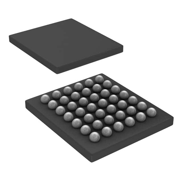
- Part No.:
- BQ25898YFFR
- Manufacturer:
- Texas Instruments
- Category:
- Battery Chargers
- Package:
- 42-UFBGA, DSBGA
- Datasheet:
-
 BQ25898YFFR.pdf
- Description:
- IC BATT CHG LI-ION 1CELL 42DSBGA
- Quantity:
- Payment:

- Shipping:

Inventory:5,589
Please send an inquiry. Send us your inquiry, and we will respond immediately.
Product details
Overview
BQ25898YFFR from Texas Instruments is a highly-integrated 4-A I²C-controlled single-cell Li-ion/Li-polymer battery charger with MaxCharge™ technology, supporting 3.9 V to 14 V input voltage range, 4.208 V ±0.5% charge voltage regulation, and USB On-the-Go boost mode (4.5–5.5 V, up to 2.4 A). It delivers fast charging for smartphones and tablets with integrated power path management, Input Current Optimizer (ICO), and remote battery sensing.
For engineers reviewing the BQ25898YFFR datasheet, BQ25898YFFR pinout, BQ25898YFFR application, or BQ25898YFFR equivalent, key selection considerations include its 42-ball DSBGA package, 1.5-MHz buck switching frequency, NVDC power path enabling instant-on operation, integrated ADC for system monitoring, and support for USB BC1.2/DCP/MaxCharge™ adapter detection.
Technical Context
The BQ25898YFFR implements a synchronous buck converter with integrated RBFET, HSFET, LSFET, and BATFET - achieving 92% charge efficiency at 3 A and 91% at 4 A. Its power path architecture maintains SYS above 3.5 V even with deeply discharged or absent battery via NVDC control.
It supports dual-mode USB OTG boost (1.5 MHz / 500 kHz) with hiccup-mode overcurrent protection and integrates critical analog functions: 7-bit ADC for VBUS/BAT/SYS/TS/ICHG monitoring, programmable D+/D− handshake for high-voltage adapters, and resistance compensation (IRCOMP) for accurate cell-terminal voltage regulation.
Key Specifications
| Parameter | Value and Actual Design Meaning |
|---|---|
| Charge Current | Up to 4.032 A - enables sub-1-hour fast charging for 2000–3000 mAh smartphone batteries. |
| Input Voltage Range | 3.9 V to 14 V - supports USB 2.0/3.0, legacy wall adapters, and high-voltage fast-charging sources like Qualcomm Quick Charge. |
| Charge Voltage Accuracy | ±0.5% at 4.208 V - ensures precise Li-ion cell termination to maximize cycle life and safety compliance. |
| OTG Boost Output | Adjustable 4.5–5.5 V, up to 2.4 A - powers USB peripherals directly from battery without external boost IC. |
| Power Path Control | NVDC architecture with 3.5 V minimum SYS regulation - sustains system operation during battery depletion or removal. |
| Thermal Regulation | Programmable 120°C junction threshold - dynamically reduces charge current to prevent thermal runaway in compact layouts. |
| Package | 2.8 mm × 2.5 mm, 42-ball DSBGA - ultra-compact footprint optimized for thin mobile PCBs with minimal thermal pad area. |
Pinout & Package
Package: 42-ball DSBGA (YFF), 2.8 mm × 2.5 mm, 0.4 mm pitch, bottom-side thermal pad.
| Pin/Terminal | Circuit Role | Design Meaning |
|---|---|---|
| VBUS | Input power rail | Accepts 3.9–14 V source; connects internally to reverse-blocking FET (RBFET) source; requires local 1-µF ceramic decoupling. |
| BAT | Battery terminal | Direct connection to Li-ion anode; internal 5-mΩ BATFET enables low-loss discharge up to 9 A peak. |
| SYS | System power rail | Regulated output (≥3.5 V) supplied by BATFET or buck converter; powers SoC/PMIC independently of battery state. |
| SW | Switching node | Drain of HSFET/source of LSFET; connects to external inductor and 0.047 µF bootstrap capacitor to BTST. |
| BTST | High-side gate driver supply | Supplies bootstrap circuit for HSFET gate drive; requires 0.047 µF capacitor to SW. |
| REGN | Low-side gate driver LDO | 6-V regulated output powering TS bias and internal logic; requires 4.7 µF ceramic capacitor to AGND. |
| TS | Battery temperature sense | Analog input for NTC thermistor divider; suspends charge if outside JEITA-compliant window. |
| I²C SDA/SCL | Configuration interface | 7-bit address 0x6B (BQ25898 variant); enables real-time adjustment of charge voltage/current, OTG settings, and safety thresholds. |
| QON | BATFET control | Active-low signal to exit ship mode (1 s pulse) or trigger full system reset (19.5 s pulse). |
| INT/STAT | Fault/status reporting | Open-drain outputs: INT pulses on fault; STAT blinks 1 Hz during faults, pulls low during charge. |
Key Features
| Feature | Design Value |
|---|---|
| Input Current Optimizer (ICO) | Dynamically adjusts input current limit to extract maximum power from unknown adapters without overload - eliminates manual adapter characterization. |
| Resistance Compensation (IRCOMP) | Compensates for PCB trace resistance between charger output and battery terminal - ensures ±0.5% voltage accuracy at cell anode. |
| Integrated Power MOSFETs | Full buck path (RBFET/HSFET/LSFET) + BATFET (5 mΩ) - removes 5 discrete FETs and associated gate drivers from BOM. |
| USB OTG Boost Flexibility | Selectable 500 kHz / 1.5 MHz switching and 4.5–5.5 V output - balances efficiency vs. EMI for diverse peripheral loads. |
| Ship Mode Leakage | 12 µA quiescent current with BATFET disabled - extends shelf life to >1 year for pre-shipped devices. |
Applications
| Smartphone Fast Charging | Tablet Power Management |
|---|---|
|
Use Scenario: High-power USB-C or proprietary fast-charge adapter delivering 9 V/2 A to a 3000 mAh Li-ion battery. IC Role / Device Role / Timing Role: Primary battery charger and system power arbiter - manages input power allocation between battery charging and real-time SoC load. Use Value: Achieves 0–80% charge in <45 min while maintaining SYS ≥3.5 V for uninterrupted app execution and display backlight. |
Use Scenario: Dual-role tablet supporting both host-mode USB peripherals and battery-powered operation. IC Role / Device Role / Timing Role: USB On-the-Go (OTG) boost controller and NVDC power path manager - supplies 5 V/1.5 A to USB devices while regulating SYS from battery. Use Value: Enables plug-and-play peripheral use (keyboard, storage) without external boost IC or firmware intervention. |
| Portable Medical Monitor | Industrial Handheld Scanner |
|
Use Scenario: Battery-backed medical device requiring JEITA-compliant charging across ambient temperatures from –20°C to 55°C. IC Role / Device Role / Timing Role: Temperature-aware battery manager - monitors TS pin with NTC, enforces JEITA profile, and halts charge outside safe zones. Use Value: Prevents lithium plating at low temperatures and thermal runaway at high temperatures - meets IEC 62368-1 safety requirements. |
Use Scenario: Rugged handheld scanner operating from single-cell Li-ion with frequent deep-discharge cycles and cold storage. IC Role / Device Role / Timing Role: Low-leakage ship-mode controller and instant-on power manager - maintains RTC and memory during storage, boots instantly on button press. Use Value: Reduces battery drain to 12 µA in ship mode and guarantees system wake-up within 10 ms even with 0 V battery. |
Equivalent & Alternatives
The following parts are listed as comparable options for similar single-cell fast charger applications.
| Alternative Part | Technical Difference | Application Difference | Selection Advice |
|---|---|---|---|
| BQ25895YFFR | Lower max charge current (3 A vs. 4.032 A); no MaxCharge™ D+/D− handshake; fixed 5 V OTG output. | Lacks adjustable OTG voltage and high-voltage adapter negotiation - suitable only for standard USB PD or fixed 5 V sources. | Select when cost sensitivity outweighs need for 4-A charging or proprietary fast-charge protocols. |
| BQ25618RTWR | 3-A charger in 20-pin WQFN; supports USB PD 3.0 via CC logic; no integrated OTG boost; uses external BATFET. | Requires external boost IC for OTG; targets USB-C ecosystems with PD communication - not drop-in compatible. | Choose for USB-C designs needing PD negotiation and lower thermal density, accepting added BOM complexity. |
Compared with BQ25895YFFR and BQ25618RTWR, the BQ25898YFFR uniquely combines 4-A charging, integrated 4.5–5.5 V OTG boost, and MaxCharge™ adapter detection in a 2.8×2.5 mm package - making it optimal for space-constrained smartphones requiring multi-protocol fast charge.
Availability
BQ25898YFFR is available at Aetrix Electronics and suitable for smartphone fast charging, tablet OTG power delivery, and portable medical device battery management requiring stable component supply, long-term lifecycle support, and guaranteed traceable sourcing.
Supply support for BQ25898YFFR includes scheduled delivery planning, volume procurement assistance, BOM continuity management, traceable sourcing, and lifecycle availability coordination for OEM customers, industrial embedded developers, connected-device designers, and electronics production programs.
Manufacturer
Texas Instruments is a global semiconductor leader specializing in analog, embedded processing, and connectivity technologies with over 50 years of innovation in power management ICs.
The BQ25898YFFR belongs to TI's bq25xxx battery charger product line, designed specifically for high-efficiency, high-input-voltage fast charging in space-constrained mobile and portable electronics.
FAQ
What is the I²C address of the BQ25898YFFR?
The BQ25898YFFR uses a fixed 7-bit I²C slave address of 0x6B (1101011b). This differs from the pin-compatible BQ25898DYFFR (0x6A), allowing coexistence on the same bus when both variants are used in modular designs. The address is hardwired and cannot be changed via pins or registers.
Does the BQ25898YFFR support USB Battery Charging Specification v1.2?
Yes, the BQ25898YFFR supports USB BC1.2 detection for SDP, CDP, and DCP through its PSEL pin and internal detection circuitry. It identifies standard USB hosts and chargers without requiring external components, enabling automatic input current limit configuration per USB spec.
How does the Input Current Optimizer (ICO) function in the BQ25898YFFR?
The BQ25898YFFR's ICO continuously monitors VBUS and input current to detect the maximum power point of unknown adapters. It dynamically adjusts the input current limit to draw peak power without collapsing VBUS - eliminating the need for pre-characterized adapter profiles in firmware.
Can the BQ25898YFFR operate without a battery connected?
Yes, the BQ25898YFFR supports true instant-on operation with no battery or deeply discharged battery. Its NVDC power path maintains SYS ≥3.5 V directly from VBUS, allowing the host system to boot and function immediately - a critical feature for retail demo units and field-service tools.
What thermal protection mechanisms does the BQ25898YFFR implement?
The BQ25898YFFR features programmable thermal regulation that begins reducing charge current when junction temperature exceeds 120°C, plus thermal shutdown at 150°C. These protections are hardware-based and operate independently of I²C commands, ensuring fail-safe operation during sustained high-power charging.
BQ25898YFFR Specifications
- Product attributes
- Attribute value
- Manufacturer:
- Texas Instruments
- Series:
- MaxCharge™
- Package/Case:
- 42-UFBGA, DSBGA
- Packaging:
- Tape & Reel (TR)
- Product Status:
- Active
- Battery Chemistry:
- Lithium Ion/Polymer
- Number of Cells:
- 1
- Current - Charging:
- -
- Programmable Features:
- -
- Fault Protection:
- Over Current, Over Temperature
- Charge Current - Max:
- 4A
- Battery Pack Voltage:
- -
- Voltage - Supply (Max):
- 14V
- Interface:
- I2C, USB
- Operating Temperature:
- -40°C ~ 85°C (TA)
- Grade:
- -
- Qualification:
- -
- Mounting Type:
- Surface Mount
- Supplier Device Package:
- 42-DSBGA (2.8x2.5)
BQ25898YFFR FAQ
1.How can I place an order for BQ25898YFFR through Aetrix?
Please submit a Request for Quotation (RFQ) for BQ25898YFFR on Aetrix. Our sales agent will provide a competitive quotation and guide you through the order confirmation once you accept the terms.
2.Are the price and stock information for BQ25898YFFR reliable?
The price and inventory of BQ25898YFFR are updated periodically and may fluctuate due to market conditions. Stock and pricing data are typically refreshed every 24 hours. Quotation validity for BQ25898YFFR is usually 5 days.
3.What payment methods are accepted for BQ25898YFFR?
We accept Wire Transfer, PayPal, Credit Card, Western Union, MoneyGram, and Escrow for BQ25898YFFR transactions.
Note: Certain payment methods may incur a processing fee.
4.How is shipping managed for BQ25898YFFR?
BQ25898YFFR orders can be shipped via leading logistics carriers, including DHL, UPS, FedEx, TNT, or Registered Mail.
Once your BQ25898YFFR order is processed, you will receive an email with the shipment details and tracking number.
Note: Tracking information may take up to 24 hours to appear. Express delivery typically takes 3–5 business days.
5.How can I obtain technical support or documentation for BQ25898YFFR?
For technical support, including BQ25898YFFR datasheets, pinout diagrams, or application guidance, please contact our engineering support team. They can provide detailed documentation and assistance for your BQ25898YFFR requirements.
6.How does Aetrix verify that BQ25898YFFR is sourced from the original manufacturer or authorized distributors?
All BQ25898YFFR products on Aetrix are procured from qualified distributors and authorized channels. Our dedicated quality assurance team conducts strict verification, including traceability checks and, if necessary, third-party testing. This ensures that BQ25898YFFR meets industry standards.
7.What is the process for return or replacement of BQ25898YFFR?
All BQ25898YFFR units undergo pre-shipment inspection (PSI). If there is an issue with BQ25898YFFR, returns or replacements are accepted under the following conditions:
1.Quantity discrepancies, incorrect items, or visible external defects (such as breakage or corrosion), acknowledged by Aetrix.
2.The issue is reported within 90 days of delivery.
3.The BQ25898YFFR part is unused and in its original packaging.
Return procedure for BQ25898YFFR:
1.Submit a request within 90 days.
2.Obtain a Return Material Authorization (RMA) from Aetrix.
BQ25898YFFR Tags

-
BQ21040DBVR
Texas Instruments

-
MCP73812T-420I/OT
Microchip Technology
-
MCP73831T-2ACI/OT
Microchip Technology
-
MCP73832T-2ACI/OT
Microchip Technology
-
MCP73831T-2DCI/OT
Microchip Technology
-
MCP73832T-2DCI/OT
Microchip Technology
-
MCP73831T-2ATI/OT
Microchip Technology
-
MCP73832T-2ATI/OT
Microchip Technology
-
MCP73831T-5ACI/OT
Microchip Technology

-
MCP73832T-2ACI/MC
Microchip Technology
-
MCP73831T-2ACI/MC
Microchip Technology
-
MCP73831T-2ATI/MC
Microchip Technology
Tech Hub

A practical engineering guide to 3.3V and 5V logic compatibility, input thresholds, resistor dividers, translator ICs, MOSFET level shifting, I2C pull-ups, timing limits and power-sequencing risks.

The 74HC595 uses push-pull logic outputs, while the TPIC6B595 uses 50 V open-drain DMOS sinks for higher-power loads. This guide compares timing, current limits, 3.3 V interfacing, load wiring, thermal…

The 74HC595 converts serial data into eight stable parallel outputs. This guide covers pin functions, shift and storage timing, OE and MR behavior, drive-current limits, cascading, voltage compatibilit…

A technical comparison of level-sensitive latches and edge-triggered flip-flops, covering timing windows, setup and hold limits, master–slave operation, time borrowing, race-through, HDL inference and…

A D latch stores one bit while Enable controls when data can pass. This reference covers gate-level operation, truth tables, transparency, setup and hold timing, LE versus OE, common ICs and practical …

An SR latch stores one bit through cross-coupled feedback. This engineering reference covers NOR and NAND implementations, truth tables, forbidden-state recovery, gated operation, switch debouncing, fa…

Latch circuits retain one bit through feedback. This technical reference covers SR and D latches, truth tables, transparency, timing limits, latch-versus-flip-flop behavior, applications and common log…

An engineering guide to LED driver operation, constant-current and constant-voltage outputs, linear and switching topologies, dimming, IC selection, calculations, replacement compatibility, and fault c…

Operational amplifier guide covering op amp basics, feedback, ideal vs real op amps, common configurations, buffer circuits, offset, bias current, gain-bandwidth, slew rate, rail-to-rail limits and sel…

Jumper cables guide covering safe connection order, red and black clamp placement, final ground connection, cable gauge, length, clamp quality, copper vs CCA cables, jump starter comparison and battery…


