
 My Inquiry
 My Account


Texas Instruments BQ27505YZGR-J3
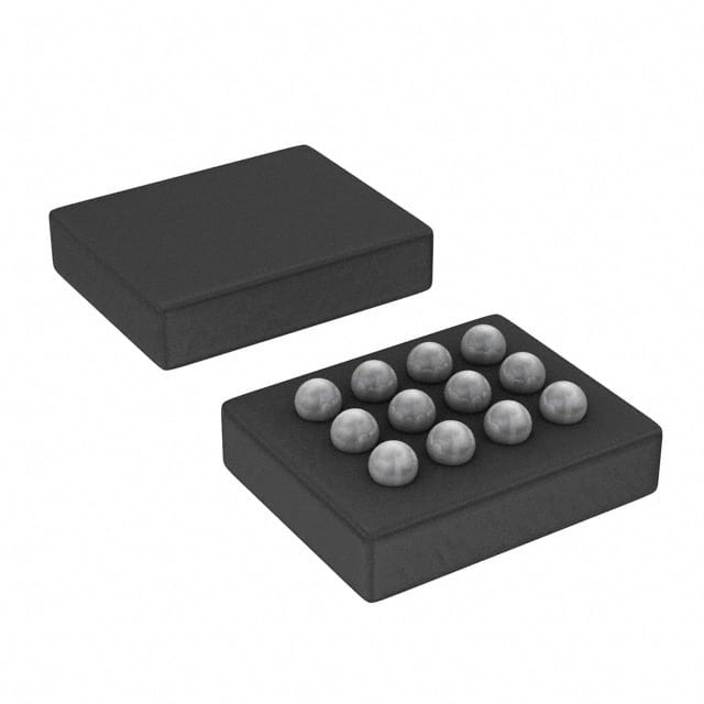
- Part No.:
- BQ27505YZGR-J3
- Manufacturer:
- Texas Instruments
- Category:
- Battery Management
- Package:
- 12-UFBGA, DSBGA
- Datasheet:
-
 BQ27505YZGR-J3.pdf
- Description:
- IC FUEL GAUGE LI-ION 1CL 12DSBGA
- Quantity:
- Payment:

- Shipping:

Inventory:2,677
Please send an inquiry. Send us your inquiry, and we will respond immediately.
Product details
Overview
BQ27505YZGR-J3 from Texas Instruments is a system-side Impedance Track™ fuel gauge IC for single-cell Li-ion battery packs, providing real-time remaining capacity (mAh), state-of-charge (%), time-to-empty (min), voltage (mV), temperature (°C), and state-of-health (%). It interfaces via 400-kHz I²C, uses a 10 mΩ sense resistor, and resides on the host system main board-not inside the battery pack. It supports embedded or removable battery configurations in space-constrained portable electronics.
For engineers reviewing the BQ27505YZGR-J3 datasheet, BQ27505YZGR-J3 pinout, BQ27505YZGR-J3 application, or BQ27505YZGR-J3 equivalent, key selection considerations include its NanoFree™ CSP-12 package (2.43 mm × 1.96 mm), integrated coulomb counter with 14-bit resolution, internal temperature sensor (–40°C to 85°C operating range), configurable SOC interrupt, and support for battery insertion detection and low-battery warning signals.
Technical Context
The BQ27505YZGR-J3 implements Texas Instruments' patented Impedance Track™ algorithm to model battery discharge curves and dynamically adjust for aging, self-discharge, and temperature/rate inefficiencies-achieving <1% SOC error across lifetime and conditions. It performs dual ADC measurements: a 14-bit integrating ADC for current sensing (SRP/SRN) and a 14-bit ADC for thermistor (TS) and cell voltage (BAT) inputs.
It operates in five power modes-NORMAL (114 µA), SLEEP+ (58 µA), SLEEP (19 µA), HIBERNATE (4 µA), and BAT INSERT CHECK-with automatic transitions triggered by events like charge/discharge activity or host I²C polling. Its 96-byte non-volatile data flash stores battery profiles, calibration data, and manufacturer information, accessible via sealed/unsealed access modes.
Key Specifications
| Parameter | Value and Actual Design Meaning |
|---|---|
| VCC Supply | 2.4 V to 2.6 V - Tight regulation required; decoupling with ≥0.1 µF ceramic capacitor at VCC pin essential for stable operation. |
| I²C Interface | 400 kHz standard-mode - Compatible with common microcontroller I²C peripherals; open-drain SDA/SCL require 10 kΩ pull-ups. |
| Coulomb Counter | 14-bit integrating ADC - Measures current via SRP/SRN differential input (±0.125 V range); supports 5–20 mΩ sense resistors. |
| Temperature Sensing | Internal sensor + external NTC thermistor (10.0 kΩ @ 25°C) - TS pin accepts thermistor divider; internal sensor provides backup reporting. |
| Power Modes | NORMAL (114 µA), HIBERNATE (4 µA) - Enables ultra-low-power battery monitoring during device sleep states without host intervention. |
| Data Retention | 10 years - Non-volatile data flash retains battery profile, calibration, and configuration even after power loss. |
| Operating Temp | –40°C to +85°C - Qualified for industrial and consumer portable applications including smartphones and handheld terminals. |
Pinout & Package
The BQ27505YZGR-J3 is housed in a 12-ball NanoFree™ CSP (CSP-12) package measuring 2.43 mm × 1.96 mm with 0.5 mm pitch, optimized for ultra-compact PCB layouts in mobile devices.
| Pin/Terminal | Circuit Role | Design Meaning |
|---|---|---|
| SRP / SRN | Coulomb counter analog inputs | Differential sense inputs for current measurement; connect across 5–20 mΩ resistor between PACK– and system ground. |
| BAT | Cell voltage ADC input | Measures single-cell Li-ion voltage (0–5 V range); used for OCV estimation and fuel gauging accuracy. |
| TS | Thermistor voltage sense | ADC input for external NTC network (e.g., 103AT-type); enables temperature-compensated SOC and safety monitoring. |
| BI/TOUT | Battery insertion detection & thermistor bias | Provides power and control for thermistor multiplexer; detects pack presence when configured with >1 MΩ pull-up. |
| SOC_INT | State-of-charge interrupt output | Open-drain signal pulses on configurable SOC thresholds; used to wake host MCU or trigger UI alerts. |
| BAT_LOW / BAT_GD | Dedicated status outputs | Push-pull active-high BAT_LOW and active-low BAT_GD indicate low-voltage condition and pack health status. |
| SDA / SCL | I²C serial interface | Standard 400-kHz I²C bus lines; require external 10 kΩ pull-ups to VCC for reliable communication with host processor. |
| VCC / VSS | Power supply and ground | VCC must be tightly regulated (2.4–2.6 V); VSS is system ground reference for all analog and digital circuitry. |
Key Features
| Feature | Design Value |
|---|---|
| Impedance Track™ Algorithm | Delivers <1% state-of-charge error over battery lifetime by modeling impedance changes due to aging, temperature, and load rate. |
| Integrated Coulomb Counter | 14-bit resolution integrating ADC with ±0.034% FSR INL enables precise mAh accumulation without external precision op-amps. |
| Configurable Interrupts | SOC_INT, BAT_LOW, and BAT_GD outputs support programmable thresholds and polarity-reducing host polling overhead and power use. |
| Non-Volatile Data Flash | 96 bytes of user-accessible flash store battery chemistry ID, design capacity, full charge capacity, and calibration offsets-surviving power cycles. |
| Multi-Power Mode Architecture | Five autonomous power states (including 4 µA HIBERNATE) allow continuous fuel gauging with minimal impact on system standby current. |
Applications
| Smartphone Battery Management | Digital Camera Power Monitoring |
|---|---|
|
Use Scenario: Real-time battery level display, low-battery warnings, and accurate shutdown prediction during video capture or GPS navigation. IC Role / Device Role: System-side fuel gauge that communicates SOC, TTE, and SOH to application processor via I²C-no firmware driver development needed. Use Value: Enables precise battery UX (e.g., % remaining, minutes until empty) while supporting fast-charging protocols and thermal derating logic. |
Use Scenario: Managing power during burst-mode image capture, flash charging, and extended playback-where sudden current spikes affect runtime estimates. IC Role / Device Role: Host-board-mounted coulomb counter and voltage/temperature monitor that feeds calibrated data to camera SoC power manager. Use Value: Delivers sub-1% SOC accuracy under dynamic loads using Impedance Track™, eliminating need for periodic full-discharge recalibration. |
| Handheld Terminal Runtime Estimation | MP3 Player Battery Health Tracking |
|
Use Scenario: Field-deployed logistics scanners requiring 8+ hour runtime per charge, with battery degradation tracking across 2+ years of service life. IC Role / Device Role: Fuel gauge providing SOH (%) and FCC (mAh) metrics to fleet management firmware-enabling predictive battery replacement scheduling. Use Value: Tracks capacity fade and internal resistance growth autonomously, reducing field failure rates and warranty claims. |
Use Scenario: Portable audio players with user-replaceable batteries needing accurate "time remaining" during variable-bitrate playback and Bluetooth streaming. IC Role / Device Role: Low-power fuel gauge operating in SLEEP+ mode (58 µA) between playback sessions-maintaining SOC continuity without host wake-up. Use Value: Extends usable battery life by minimizing background current draw while preserving <1% gauging accuracy across charge cycles. |
Equivalent & Alternatives
The following parts are listed as comparable options for similar fuel gauge applications.
| Alternative Part | Technical Difference | Application Difference | Selection Advice |
|---|---|---|---|
| BQ27426YZFT | Same CSP-12 package, but newer generation with enhanced Impedance Track™ v2, lower quiescent current (3 µA hibernate), and improved low-current accuracy. | Requires updated firmware for extended command set; supports tighter SOC tolerance (<0.5%) under light loads. | Preferred for new designs targeting longer battery life and higher accuracy-especially in always-on wearable or IoT edge devices. |
| BQ27510-G3YZFT | Pin-compatible CSP-12 variant with identical pinout and register map, but includes factory-programmed gas gauge parameters and enhanced ESD rating (4 kV HBM). | Reduces production calibration effort; supports faster time-to-market for battery pack integrators. | Recommended when pre-calibrated out-of-box performance and robustness against handling ESD are critical in high-volume manufacturing. |
Compared with BQ27505YZGR-J3, the BQ27426YZFT offers superior low-power operation and next-gen algorithm fidelity, while the BQ27510-G3YZFT delivers plug-and-play readiness and higher ESD immunity-both retain full software compatibility but address distinct design priorities: accuracy evolution versus production scalability.
Availability
BQ27505YZGR-J3 is available at Aetrix Electronics and suitable for smartphone battery management, handheld terminal runtime estimation, and digital camera power monitoring requiring stable component supply across multi-year production cycles.
Supply support for BQ27505YZGR-J3 includes scheduled delivery planning, volume procurement assistance, BOM continuity management, traceable sourcing, and lifecycle availability coordination for OEM customers, industrial embedded developers, connected-device designers, and electronics production programs.
Manufacturer
Texas Instruments is a global semiconductor leader specializing in analog, embedded processing, and power management technologies, with decades of leadership in battery management ICs.
The BQ27505YZGR-J3 belongs to TI's Impedance Track™ fuel gauge product line, designed specifically for high-accuracy, system-side battery monitoring in space-constrained portable electronics where embedded firmware overhead must be minimized.
FAQ
What is the primary function of the BQ27505YZGR-J3 in a battery-powered system?
The BQ27505YZGR-J3 serves as a system-side fuel gauge IC that accurately reports remaining capacity (mAh), state-of-charge (%), time-to-empty (min), voltage (mV), temperature (°C), and state-of-health (%) for single-cell Li-ion batteries. It resides on the host main board-not inside the battery-and uses TI's Impedance Track™ algorithm to deliver <1% SOC error across operating conditions and battery lifetime. The BQ27505YZGR-J3 eliminates the need for complex host-side gauging firmware by providing ready-to-use metrics via I²C.
Does the BQ27505YZGR-J3 require an external sense resistor, and what value is recommended?
Yes, the BQ27505YZGR-J3 requires an external current-sense resistor connected between PACK– and system ground. The datasheet specifies a range of 5 mΩ to 20 mΩ, with 10 mΩ being the typical recommendation. This resistor interfaces directly with the SRP and SRN pins, feeding the 14-bit integrating ADC. Using a low-value resistor minimizes power loss and thermal drift while maintaining sufficient signal for accurate coulomb counting in the BQ27505YZGR-J3.
Can the BQ27505YZGR-J3 operate with both embedded and removable battery packs?
Yes, the BQ27505YZGR-J3 is explicitly designed to support both embedded (non-removable) and removable battery pack configurations. It connects only to PACK+, PACK–, and T (thermistor) terminals-no direct connection to battery cells is required. The BI/TOUT pin enables battery insertion detection, and the device's architecture allows seamless integration whether the battery is soldered onto the PCB or hot-swappable via a connector. This flexibility is confirmed in the BQ27505YZGR-J3 datasheet Section 1.3 and Typical Application diagram.
What power modes does the BQ27505YZGR-J3 support, and how do they impact system power consumption?
The BQ27505YZGR-J3 supports five autonomous power modes: NORMAL (114 µA), SLEEP+ (58 µA), SLEEP (19 µA), HIBERNATE (4 µA), and BAT INSERT CHECK. These modes reduce current draw based on activity-e.g., entering HIBERNATE during prolonged idle periods while retaining flash-stored battery data. The BQ27505YZGR-J3 transitions automatically between modes or can be commanded by the host, enabling aggressive power savings without sacrificing fuel gauging continuity or accuracy.
Is the BQ27505YZGR-J3 pin-compatible with other members of the BQ275xx family?
No, the BQ27505YZGR-J3 is not fully pin-compatible with later BQ275xx variants such as the BQ27510-G3YZFT or BQ27541-G1YZFT. While all use the CSP-12 package, pin functions differ-for example, the BQ27510-G3 adds dedicated ALERT and QEN pins not present in the BQ27505YZGR-J3 pinout. The BQ27505YZGR-J3 pin assignment is fixed per Table 2-1 in SLUS986A, and substitution requires PCB layout revision unless verified as drop-in by TI documentation-which does not apply to this part.
BQ27505YZGR-J3 Specifications
- Product attributes
- Attribute value
- Manufacturer:
- Texas Instruments
- Series:
- Impedance Track™
- Package/Case:
- 12-UFBGA, DSBGA
- Packaging:
- Tape & Reel (TR)
- Product Status:
- Active
- Function:
- Battery Monitor
- Battery Chemistry:
- Lithium Ion
- Number of Cells:
- 1
- Fault Protection:
- -
- Interface:
- I2C
- Operating Temperature:
- -40°C ~ 85°C (TA)
- Grade:
- -
- Qualification:
- -
- Mounting Type:
- Surface Mount
- Supplier Device Package:
- 12-DSBGA
BQ27505YZGR-J3 FAQ
1.How can I place an order for BQ27505YZGR-J3 through Aetrix?
Please submit a Request for Quotation (RFQ) for BQ27505YZGR-J3 on Aetrix. Our sales agent will provide a competitive quotation and guide you through the order confirmation once you accept the terms.
2.Are the price and stock information for BQ27505YZGR-J3 reliable?
The price and inventory of BQ27505YZGR-J3 are updated periodically and may fluctuate due to market conditions. Stock and pricing data are typically refreshed every 24 hours. Quotation validity for BQ27505YZGR-J3 is usually 5 days.
3.What payment methods are accepted for BQ27505YZGR-J3?
We accept Wire Transfer, PayPal, Credit Card, Western Union, MoneyGram, and Escrow for BQ27505YZGR-J3 transactions.
Note: Certain payment methods may incur a processing fee.
4.How is shipping managed for BQ27505YZGR-J3?
BQ27505YZGR-J3 orders can be shipped via leading logistics carriers, including DHL, UPS, FedEx, TNT, or Registered Mail.
Once your BQ27505YZGR-J3 order is processed, you will receive an email with the shipment details and tracking number.
Note: Tracking information may take up to 24 hours to appear. Express delivery typically takes 3–5 business days.
5.How can I obtain technical support or documentation for BQ27505YZGR-J3?
For technical support, including BQ27505YZGR-J3 datasheets, pinout diagrams, or application guidance, please contact our engineering support team. They can provide detailed documentation and assistance for your BQ27505YZGR-J3 requirements.
6.How does Aetrix verify that BQ27505YZGR-J3 is sourced from the original manufacturer or authorized distributors?
All BQ27505YZGR-J3 products on Aetrix are procured from qualified distributors and authorized channels. Our dedicated quality assurance team conducts strict verification, including traceability checks and, if necessary, third-party testing. This ensures that BQ27505YZGR-J3 meets industry standards.
7.What is the process for return or replacement of BQ27505YZGR-J3?
All BQ27505YZGR-J3 units undergo pre-shipment inspection (PSI). If there is an issue with BQ27505YZGR-J3, returns or replacements are accepted under the following conditions:
1.Quantity discrepancies, incorrect items, or visible external defects (such as breakage or corrosion), acknowledged by Aetrix.
2.The issue is reported within 90 days of delivery.
3.The BQ27505YZGR-J3 part is unused and in its original packaging.
Return procedure for BQ27505YZGR-J3:
1.Submit a request within 90 days.
2.Obtain a Return Material Authorization (RMA) from Aetrix.
BQ27505YZGR-J3 Tags

-
BQ29700DSER
Texas Instruments

-
S-8241ABKMC-GBKT2G
ABLIC Inc.
-
S-8241ABPMC-GBPT2G
ABLIC Inc.

-
BQ27427YZFR
Texas Instruments

-
BQ27426YZFR
Texas Instruments

-
STC3117IJT
STMicroelectronics

-
STC3115IJT
STMicroelectronics

-
BQ76925RGER
Texas Instruments
-
NPM1100-QDAA-R
Nordic Semiconductor ASA

-
BQ27441DRZR-G1A
Texas Instruments

-
STC3115AIQT
STMicroelectronics

-
S-8252AAL-M6T1U
ABLIC Inc.
Tech Hub

A practical engineering guide to 3.3V and 5V logic compatibility, input thresholds, resistor dividers, translator ICs, MOSFET level shifting, I2C pull-ups, timing limits and power-sequencing risks.

The 74HC595 uses push-pull logic outputs, while the TPIC6B595 uses 50 V open-drain DMOS sinks for higher-power loads. This guide compares timing, current limits, 3.3 V interfacing, load wiring, thermal…

The 74HC595 converts serial data into eight stable parallel outputs. This guide covers pin functions, shift and storage timing, OE and MR behavior, drive-current limits, cascading, voltage compatibilit…

A technical comparison of level-sensitive latches and edge-triggered flip-flops, covering timing windows, setup and hold limits, master–slave operation, time borrowing, race-through, HDL inference and…

A D latch stores one bit while Enable controls when data can pass. This reference covers gate-level operation, truth tables, transparency, setup and hold timing, LE versus OE, common ICs and practical …

An SR latch stores one bit through cross-coupled feedback. This engineering reference covers NOR and NAND implementations, truth tables, forbidden-state recovery, gated operation, switch debouncing, fa…

Latch circuits retain one bit through feedback. This technical reference covers SR and D latches, truth tables, transparency, timing limits, latch-versus-flip-flop behavior, applications and common log…

An engineering guide to LED driver operation, constant-current and constant-voltage outputs, linear and switching topologies, dimming, IC selection, calculations, replacement compatibility, and fault c…

Operational amplifier guide covering op amp basics, feedback, ideal vs real op amps, common configurations, buffer circuits, offset, bias current, gain-bandwidth, slew rate, rail-to-rail limits and sel…

Jumper cables guide covering safe connection order, red and black clamp placement, final ground connection, cable gauge, length, clamp quality, copper vs CCA cables, jump starter comparison and battery…


