
 My Inquiry
 My Account


Texas Instruments BQ3285S-SB2
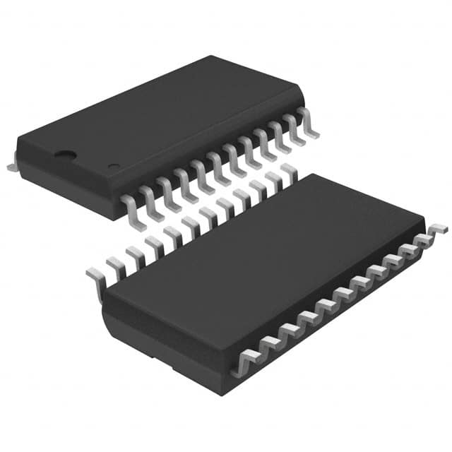
- Part No.:
- BQ3285S-SB2
- Manufacturer:
- Texas Instruments
- Category:
- Real Time Clocks
- Package:
- 24-SOIC (0.295", 7.50mm Width)
- Datasheet:
-
 BQ3285S-SB2.pdf
- Description:
- IC RTC CLK/CALENDAR PAR 24SOIC
- Quantity:
- Payment:

- Shipping:

Inventory:391
Please send an inquiry. Send us your inquiry, and we will respond immediately.
Product details
Overview
BQ3285S-SB2 from Texas Instruments is a low-power, 24-pin SOIC real-time clock (RTC) IC providing time-of-day and 100-year calendar with alarm, programmable square-wave output, three maskable interrupts, and 114 bytes of nonvolatile RAM. It operates on +5V supply with <0.5µA battery load and supports Intel/Motorola bus timing for IBM AT-compatible systems and embedded industrial controllers.
For engineers reviewing the BQ3285S-SB2 datasheet, BQ3285S-SB2 pinout, BQ3285S-SB2 application, or BQ3285S-SB2 equivalent, key selection considerations include its 160ns cycle time, BCD/binary data format flexibility, automatic leap-year correction, 32.768kHz crystal interface, and dual-bus timing compatibility - all critical for legacy system replacement and battery-backed timekeeping in space-constrained designs.
Technical Context
The BQ3285S-SB2 implements a fully autonomous RTC core with integrated oscillator control, frequency divider, and update-cycle logic synchronized to a 32.768kHz crystal. Its register-mapped architecture includes four dedicated control/status registers (A–D) and a 128-byte memory map split into 14 clock/control bytes and 114 general-purpose NV RAM bytes.
Interrupt generation is decoupled across three independent sources - periodic (122µs–500ms), alarm (second-to-day granularity via "don't care" byte masking), and update-ended - each with individual enable/flag bits in registers B and C. Bus interface behavior is dynamically selected via MOT pin, enabling direct integration into either Intel-style (ALE/RD/WR) or Motorola-style (DS/R/W/AS) microprocessor buses without external glue logic.
Key Specifications
| Parameter | Value and Actual Design Meaning |
|---|---|
| Supply Voltage | 4.5V to 5.5V - ensures compatibility with standard TTL/CMOS 5V systems and stable operation across industrial voltage tolerances |
| Battery Current | <0.5µA at VBC = 3V - enables multi-year backup from a single CR2032 cell without significant capacity drain |
| Cycle Time | 160ns - supports high-speed CPU bus access without wait states in 8-bit microprocessor systems |
| Nonvolatile RAM | 114 bytes - provides ample storage for configuration, calibration, or event logs retained during main power loss |
| Square-Wave Output | 13 selectable frequencies (2Hz–8.192kHz) - delivers precise timing reference or clock signal for peripherals or watchdog circuits |
| Alarm Flexibility | Per-second to per-day via "don't care" byte masking - allows software-defined wake-up intervals without hardware modification |
| Update Cycle | 1-second period with UIP flag and tBUC = 244µs setup window - enables deterministic, glitch-free time register reads in interrupt-driven firmware |
Pinout & Package
Package: 24-pin SOIC (DW), 0.300" wide, RoHS-compliant, MSL Level-1, rated for 0°C to +70°C operation.
| Pin/Terminal | Circuit Role | Design Meaning |
|---|---|---|
| VCC | Primary power supply input | +5V main system rail; internal switch-over circuit engages BC when VCC drops below ~4.17V |
| BC | Backup cell input | Connects to 3V lithium coin cell; powers RTC and RAM during main power failure |
| MOT | Bus timing select | Tied to VSS for Intel timing (RD/WR/ALE), VCC for Motorola timing (DS/R/W/AS); internal 30kΩ pull-down |
| AD0–AD7 | Multiplexed address/data bus | Time-multiplexed I/O: address latched on AS falling edge, data transferred in subsequent phase |
| CS, AS, DS, R/W | Bus control inputs | Enable decoding, demultiplexing, strobing, and direction control - behavior varies by MOT setting per Table 1 |
| INT | Open-drain interrupt output | Asserts low on enabled interrupt events; cleared automatically when register C is read |
| SQW | Programmable square-wave output | Outputs selected frequency only when SQWE bit = 1; held low otherwise |
| RCL | RAM clear input | Active-low pushbutton interface; clears 114 NV RAM bytes to 0xFF after ≥125ms assertion |
| X1/X2 | Crystal oscillator terminals | Accepts 32.768kHz tuning-fork crystal (e.g., Daiwa DT-26, 6pF load); no external caps required |
| RST | Reset input | Active-low asynchronous reset; disables INT and places device in known state; may be tied to VCC to retain control bits across power cycles |
Key Features
| Feature | Design Value |
|---|---|
| Direct IBM AT RTC replacement | Pin- and function-compatible with DS1285 and MC146818A - enables drop-in upgrade of legacy PC motherboards and industrial controllers |
| Selectable bus timing | Single MOT pin configures full Intel or Motorola protocol stack - eliminates need for bus translation logic or firmware abstraction layers |
| Automatic calendar correction | Hardware leap-year adjustment and day-of-week calculation - removes software burden of date arithmetic in embedded firmware |
| Write-protection during power fail | Automatic register lockout when VCC falls below 4.17V - prevents corruption of time, calendar, and NV RAM during brownout conditions |
| Low-power battery operation | 0.3µA typical ICCB - extends coin-cell life beyond 10 years while maintaining accurate timekeeping and data retention |
| Programmable interrupt sources | Three independent, maskable flags (periodic/alarm/update-ended) with dedicated enable bits - enables flexible power management and event scheduling |
Applications
| Industrial PLC Time Stamping | Legacy PC Motherboard RTC |
|---|---|
Use Scenario: Recording sensor event timestamps in programmable logic controllers operating in unattended factory environments. IC Role / Device Role / Timing Role: Primary real-time clock source maintaining wall-clock time and date with battery backup during AC power interruptions. Use Value: Ensures traceable, ISO-compliant time stamps for process logs and quality records without reliance on network time protocols or host CPU uptime. |
Use Scenario: Replacing aging RTC chips on IBM AT-compatible PC motherboards used in medical imaging or test equipment. IC Role / Device Role / Timing Role: Drop-in functional and pin-compatible RTC providing calendar, alarm, and NV RAM for BIOS timekeeping and CMOS configuration storage. Use Value: Eliminates redesign effort and qualification risk while restoring reliable timekeeping and extending service life of legacy systems. |
| Energy Meter Data Logging | Smart Building HVAC Controller |
Use Scenario: Capturing cumulative kWh consumption at 15-minute intervals in utility-grade electricity meters with tamper-resistant design. IC Role / Device Role / Timing Role: High-accuracy time base for scheduled data capture and secure timestamping of meter readings stored in on-chip NV RAM. Use Value: Maintains sub-second time accuracy over temperature and battery voltage variations, ensuring regulatory compliance for billing data integrity. |
Use Scenario: Scheduling heating/cooling cycles and occupancy-based setpoint adjustments in standalone HVAC controllers deployed in commercial buildings. IC Role / Device Role / Timing Role: Local timekeeper enabling daily/weekly schedule execution and daylight saving time (DST) auto-adjustment without cloud dependency. Use Value: Reduces energy waste through precise temporal control while supporting maintenance logging and remote diagnostics with accurate timestamps. |
Equivalent & Alternatives
The following parts are listed as comparable options for similar real-time clock applications.
| Alternative Part | Technical Difference | Application Difference | Selection Advice |
|---|---|---|---|
| DS1285 | Same pinout and register map; requires external capacitor for oscillator stability; higher battery current (~1µA) | Identical IBM AT replacement use case; less integrated oscillator control | Choose DS1285 only if existing board layout uses its specific crystal load requirements and higher battery drain is acceptable |
| PCF8583 | I²C interface (vs parallel bus); 24-pin DIP only; no MOT pin or bus timing selection; 64 bytes NV RAM | Suitable for new designs with I²C master available; not compatible with legacy AT bus systems | Select PCF8583 for cost-sensitive, space-constrained new designs where I²C simplifies routing and reduces MCU GPIO usage |
Compared with DS1285 and PCF8583, the BQ3285S-SB2 uniquely combines parallel bus flexibility (Intel/Motorola), ultra-low battery current, and full calendar functionality in a surface-mount SOIC package - making it the optimal choice for retrofitting legacy 5V systems requiring long-term, maintenance-free timekeeping.
Availability
BQ3285S-SB2 is available at Aetrix Electronics and suitable for industrial PLC time stamping, legacy PC motherboard RTC replacement, energy meter data logging, and smart building HVAC controller applications requiring stable component supply and long lifecycle support.
Supply support for BQ3285S-SB2 includes scheduled delivery planning, volume procurement assistance, BOM continuity management, traceable sourcing, and lifecycle availability coordination for OEM customers, industrial embedded developers, connected-device designers, and electronics production programs.
Manufacturer
Texas Instruments is a global semiconductor leader delivering analog and embedded processing solutions, with deep expertise in precision timing, power management, and industrial interface technologies.
The BQ3285S-SB2 belongs to TI's legacy real-time clock product line, designed specifically for robust, battery-backed timekeeping in 5V industrial and computing systems where reliability, pin compatibility, and long-term availability are critical.
FAQ
What is the primary function of the BQ3285S-SB2?
The BQ3285S-SB2 is a real-time clock IC that provides accurate time-of-day and 100-year calendar functionality with battery backup, nonvolatile RAM storage, programmable interrupts, and square-wave output. It serves as a direct replacement for DS1285 and MC146818A in IBM AT-compatible systems and other embedded applications requiring reliable, low-power timekeeping.
Does the BQ3285S-SB2 support both Intel and Motorola bus protocols?
Yes, the BQ3285S-SB2 supports both bus architectures via the MOT pin: tie MOT to VSS for Intel timing (compatible with RD/WR/ALE signals) or to VCC for Motorola timing (compatible with DS/R/W/AS signals). This dual-mode capability eliminates the need for external bus translators and simplifies integration across different microprocessor platforms.
How does the BQ3285S-SB2 handle power failure and battery switchover?
The BQ3285S-SB2 monitors VCC continuously and initiates automatic write-protection of clock, calendar, and RAM registers when VCC falls below ~4.17V (VPFD). When VCC drops below ~3V (VBC), it seamlessly switches power to the backup cell (BC pin), sustaining RTC operation and data retention. Upon VCC recovery, it reverts to main supply and maintains register integrity throughout the transition.
What is the purpose of the RCL pin on the BQ3285S-SB2?
The RCL (RAM Clear) pin on the BQ3285S-SB2 is an active-low input that, when held low for ≥125ms, clears all 114 bytes of nonvolatile RAM to 0xFF while leaving clock, calendar, and control registers unchanged. It is intended for user-interface pushbutton use - not for connection to active logic - and features an internal 30kΩ pull-up resistor.
Can the BQ3285S-SB2 generate a 1Hz square-wave output?
Yes, the BQ3285S-SB2 can generate a 1Hz square-wave output by setting RS0–RS3 bits in Register A to 0001 (per Table 3) and enabling the SQWE bit in Register B. The 1Hz signal is derived from the 32.768kHz crystal oscillator and is commonly used for system tick generation, LED blinking, or synchronization with external peripherals.
BQ3285S-SB2 Specifications
- Product attributes
- Attribute value
- Manufacturer:
- Texas Instruments
- Series:
- -
- Package/Case:
- 24-SOIC (0.295", 7.50mm Width)
- Packaging:
- Bulk
- Product Status:
- Active
- Programmable:
- Not Verified
- Type:
- Clock/Calendar
- Features:
- Alarm, Daylight Savings, Leap Year, NVSRAM, Square Wave Output
- Memory Size:
- 114B
- Time Format:
- HH:MM:SS (12/24 hr)
- Date Format:
- YY-MM-DD-dd
- Interface:
- Parallel
- Voltage - Supply:
- 4.5V ~ 5.5V
- Voltage - Supply, Battery:
- 2.5V ~ 4V
- Current - Timekeeping (Max):
- -
- Operating Temperature:
- 0°C ~ 70°C
- Mounting Type:
- Surface Mount
- Grade:
- -
- Qualification:
- -
- Supplier Device Package:
- 24-SOIC
BQ3285S-SB2 FAQ
1.How can I place an order for BQ3285S-SB2 through Aetrix?
Please submit a Request for Quotation (RFQ) for BQ3285S-SB2 on Aetrix. Our sales agent will provide a competitive quotation and guide you through the order confirmation once you accept the terms.
2.Are the price and stock information for BQ3285S-SB2 reliable?
The price and inventory of BQ3285S-SB2 are updated periodically and may fluctuate due to market conditions. Stock and pricing data are typically refreshed every 24 hours. Quotation validity for BQ3285S-SB2 is usually 5 days.
3.What payment methods are accepted for BQ3285S-SB2?
We accept Wire Transfer, PayPal, Credit Card, Western Union, MoneyGram, and Escrow for BQ3285S-SB2 transactions.
Note: Certain payment methods may incur a processing fee.
4.How is shipping managed for BQ3285S-SB2?
BQ3285S-SB2 orders can be shipped via leading logistics carriers, including DHL, UPS, FedEx, TNT, or Registered Mail.
Once your BQ3285S-SB2 order is processed, you will receive an email with the shipment details and tracking number.
Note: Tracking information may take up to 24 hours to appear. Express delivery typically takes 3–5 business days.
5.How can I obtain technical support or documentation for BQ3285S-SB2?
For technical support, including BQ3285S-SB2 datasheets, pinout diagrams, or application guidance, please contact our engineering support team. They can provide detailed documentation and assistance for your BQ3285S-SB2 requirements.
6.How does Aetrix verify that BQ3285S-SB2 is sourced from the original manufacturer or authorized distributors?
All BQ3285S-SB2 products on Aetrix are procured from qualified distributors and authorized channels. Our dedicated quality assurance team conducts strict verification, including traceability checks and, if necessary, third-party testing. This ensures that BQ3285S-SB2 meets industry standards.
7.What is the process for return or replacement of BQ3285S-SB2?
All BQ3285S-SB2 units undergo pre-shipment inspection (PSI). If there is an issue with BQ3285S-SB2, returns or replacements are accepted under the following conditions:
1.Quantity discrepancies, incorrect items, or visible external defects (such as breakage or corrosion), acknowledged by Aetrix.
2.The issue is reported within 90 days of delivery.
3.The BQ3285S-SB2 part is unused and in its original packaging.
Return procedure for BQ3285S-SB2:
1.Submit a request within 90 days.
2.Obtain a Return Material Authorization (RMA) from Aetrix.
BQ3285S-SB2 Tags

-
MCP7940N-I/SN
Microchip Technology

-
MCP7940MT-I/MNY
Microchip Technology

-
PCF85063ATL/1,118
NXP USA Inc.
-
MCP7940NT-I/SN
Microchip Technology

-
MCP7940NT-I/MS
Microchip Technology
-
MCP7940N-I/MS
Microchip Technology

-
PCF85063AT/AY
NXP USA Inc.

-
PCF85063TP/1Z
NXP Semiconductors

-
PCF85063ATT/AJ
NXP USA Inc.
-
MCP7940NT-E/SN
Microchip Technology
-
MCP7940NT-I/MNY
Microchip Technology
-
MCP79400T-I/SN
Microchip Technology
Tech Hub

A practical engineering guide to 3.3V and 5V logic compatibility, input thresholds, resistor dividers, translator ICs, MOSFET level shifting, I2C pull-ups, timing limits and power-sequencing risks.

The 74HC595 uses push-pull logic outputs, while the TPIC6B595 uses 50 V open-drain DMOS sinks for higher-power loads. This guide compares timing, current limits, 3.3 V interfacing, load wiring, thermal…

The 74HC595 converts serial data into eight stable parallel outputs. This guide covers pin functions, shift and storage timing, OE and MR behavior, drive-current limits, cascading, voltage compatibilit…

A technical comparison of level-sensitive latches and edge-triggered flip-flops, covering timing windows, setup and hold limits, master–slave operation, time borrowing, race-through, HDL inference and…

A D latch stores one bit while Enable controls when data can pass. This reference covers gate-level operation, truth tables, transparency, setup and hold timing, LE versus OE, common ICs and practical …

An SR latch stores one bit through cross-coupled feedback. This engineering reference covers NOR and NAND implementations, truth tables, forbidden-state recovery, gated operation, switch debouncing, fa…

Latch circuits retain one bit through feedback. This technical reference covers SR and D latches, truth tables, transparency, timing limits, latch-versus-flip-flop behavior, applications and common log…

An engineering guide to LED driver operation, constant-current and constant-voltage outputs, linear and switching topologies, dimming, IC selection, calculations, replacement compatibility, and fault c…

Operational amplifier guide covering op amp basics, feedback, ideal vs real op amps, common configurations, buffer circuits, offset, bias current, gain-bandwidth, slew rate, rail-to-rail limits and sel…

Jumper cables guide covering safe connection order, red and black clamp placement, final ground connection, cable gauge, length, clamp quality, copper vs CCA cables, jump starter comparison and battery…


