
 My Inquiry
 My Account


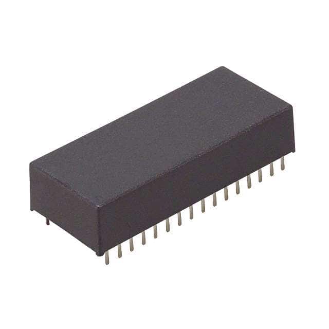
Texas Instruments BQ4013LYMA-70N
- Part No.:
- BQ4013LYMA-70N
- Manufacturer:
- Texas Instruments
- Category:
- Memory
- Package:
- 32-DIP Module (0.610", 15.49mm)
- Datasheet:
-
 BQ4013LYMA-70N.pdf
- Description:
- IC NVSRAM 1MBIT PAR 32DIP MODULE
- Quantity:
- Payment:

- Shipping:

Inventory:298
Please send an inquiry. Send us your inquiry, and we will respond immediately.
Product details
Overview
BQ4013LYMA-70N from Texas Instruments is a 128 k × 8 nonvolatile SRAM with integrated lithium backup, designed for data retention during power loss in industrial embedded systems. It operates at 3.3 V (±10%), features 70 ns access time, automatic write-protection at VPFD = 2.90 V (typ), and retains data for ≥10 years without external power.
For engineers reviewing the BQ4013LYMA-70N datasheet, BQ4013LYMA-70N pinout, BQ4013LYMA-70N application, or BQ4013LYMA-70N equivalent, this page delivers verified technical context, pin-level circuit roles, real-world use cases in power-fail-critical systems, and validated alternative options for legacy design continuity.
Technical Context
The BQ4013LYMA-70N integrates a 131,072-word × 8-bit CMOS SRAM core with on-module lithium coin cell and autonomous power-fail detection circuitry. Its VPFD threshold is fixed at 2.90 V (typ) for 3.3-V systems, triggering write-protection and seamless switchover to backup supply before VCC drops below VSO = 2.9 V.
During valid VCC operation, it behaves as a standard asynchronous SRAM with CE/OE/WE control logic and full read/write timing compliance per JEDEC standards. Upon power-up, tCER = 85 ms (max) enforces write-protection hold-off to ensure processor stabilization before resuming normal access.
Key Specifications
| Parameter | Value and Actual Design Meaning |
|---|---|
| Memory Density | 128 k × 8 (1,048,576-bit), organized as 131,072 words × 8 bits - supports byte-wide data bus interfacing without external demultiplexing. |
| Supply Voltage | 3.00 V to 3.60 V - compatible with 3.3-V logic families and tolerant of ±10% regulation error in industrial power rails. |
| Access Time | 70 ns - enables direct interface with microcontrollers and FPGAs operating up to ~12 MHz bus frequency without wait states. |
| Power-Fail Threshold | VPFD = 2.85 V (min) / 2.90 V (typ) / 2.95 V (max) - triggers deterministic write-protection before data corruption risk in brownout conditions. |
| Data Retention | ≥10 years at TA = 25°C - achieved via isolated lithium cell with <0.5% annual self-discharge prior to first power application. |
| Operating Temperature | –40°C to +85°C - qualified for industrial environments including factory automation and remote telemetry nodes. |
| Standby Current | ISB1 = 1 µA (max) with CE = VIH - minimizes battery drain during extended off-line storage or standby modes. |
Pinout & Package
32-pin DIP module (MA package), through-hole mounting, 0.6-inch width, industry-standard footprint compatible with legacy PCB layouts.
| Pin/Terminal | Circuit Role | Design Meaning |
|---|---|---|
| A0–A16 | Address inputs | 17-bit address bus supporting full 131,072-word decoding; A16 is MSB for 128k density. |
| DQ0–DQ7 | Data input/output | 8-bit bidirectional data bus; high-impedance state enforced during write-protection or CE/OE deassertion. |
| CE | Chip-enable input | Active-low enable controlling device selection; initiates tCER delay on power-up before write-enable release. |
| OE | Output-enable input | Active-low control for output drivers; allows read operations while CE remains asserted. |
| WE | Write-enable input | Active-low signal qualifying write cycles; held high during reads and automatically disabled during power-fail events. |
| VCC | Supply voltage input | Primary 3.3-V power rail; monitored continuously for VPFD violation to trigger backup switchover. |
| VSS | Ground | System reference node; decoupling capacitor required near pin for stable SRAM operation. |
| NC | No connect | Pins 1 and 30 are unconnected - must remain floating; no internal bonding or routing. |
Key Features
| Feature | Design Value |
|---|---|
| Integrated lithium backup | On-module coin cell electrically isolated until first VCC application, enabling >10-year shelf life and zero pre-use self-discharge. |
| Automatic write-protection | Hardware-enforced lockout triggered at VPFD = 2.90 V (typ); eliminates need for external supervisor IC or firmware intervention. |
| Industry-standard pinout | 32-pin DIP layout matches 1-Mb SRAM footprint - allows drop-in replacement in existing designs without PCB revision. |
| Unlimited write cycles | CMOS SRAM core supports infinite endurance under normal operation - unlike EEPROM or Flash, no wear-out mechanism. |
| Power-up stabilization guard | tCER = 85 ms (max) ensures write-disable window after VCC crosses VPFD, preventing spurious writes during processor boot. |
Applications
| Industrial Data Logger | Medical Device Configuration Storage |
|---|---|
|
Use Scenario: Battery-powered field recorder capturing sensor readings during mains outage. IC Role / Device Role / Timing Role: Nonvolatile memory preserving last-valid measurement set and calibration constants across repeated power cycles. Use Value: Eliminates need for external EEPROM write buffering or checksum validation - data integrity guaranteed by hardware-level VPFD-triggered protection. |
Use Scenario: Portable diagnostic instrument storing user preferences and calibration offsets between clinical sessions. IC Role / Device Role / Timing Role: Retentive configuration store retaining settings for >10 years without maintenance or battery replacement. Use Value: Avoids recalibration drift from volatile RAM loss; leverages built-in isolation to prevent premature cell discharge during shelf storage. |
| Telecom Base Station Clock Backup | PLC Real-Time Event Log |
|
Use Scenario: Cellular infrastructure unit maintaining accurate time-of-day during AC failure. IC Role / Device Role / Timing Role: Holding timestamp registers and sync metadata during short-duration grid interruptions. Use Value: Sustains timekeeping continuity without external RTC battery management circuitry - VPFD switchover occurs within 100 µs (tWPT max). |
Use Scenario: Factory-floor programmable logic controller logging machine fault events during brownouts. IC Role / Device Role / Timing Role: Capturing sequential event codes and timestamps into circular buffer memory with guaranteed write atomicity. Use Value: Prevents log corruption during rapid power collapse - automatic WE disable ensures partial writes never commit to memory. |
Equivalent & Alternatives
The following parts are listed as comparable options for similar nonvolatile SRAM applications.
| Alternative Part | Technical Difference | Application Difference | Selection Advice |
|---|---|---|---|
| STK13C68-J15F | 3.3-V 128k × 8 NVSRAM; 150 ns access; VPFD = 2.9 V; uses capacitor-based backup (no lithium) | Limited retention (~72 hr typical) without external supercapacitor; requires external charge circuit | Select when long-term retention is secondary to RoHS-compliant, lead-free, capacitor-backed solution. |
| DS1248W-120+ | 5-V 128k × 8 NVSRAM; 120 ns access; VPFD = 4.37 V; includes real-time clock and watchdog | Requires 5-V supply; adds RTC functionality but increases pin count and layout complexity | Select when system needs integrated timekeeping and the design already uses 5-V rails and has space for extra functions. |
Compared with BQ4013LYMA-70N, STK13C68-J15F trades 10-year retention for capacitor-based simplicity and RoHS compliance, while DS1248W-120+ adds RTC capability at the cost of 5-V dependency and slower access - making BQ4013LYMA-70N optimal for pure, low-power, long-retention 3.3-V SRAM replacement.
Availability
BQ4013LYMA-70N is available at Aetrix Electronics and suitable for industrial data loggers, medical configuration storage, telecom clock backup, and PLC event logging requiring stable component supply amid end-of-life transitions.
Supply support for BQ4013LYMA-70N includes scheduled delivery planning, volume procurement assistance, BOM continuity management, traceable sourcing, and lifecycle availability coordination for OEM customers, industrial embedded developers, connected-device designers, and electronics production programs.
Manufacturer
Texas Instruments is a global semiconductor leader specializing in analog, embedded processing, and power management technologies, with over 90 years of innovation in reliable, high-performance components.
The BQ4013LYMA-70N belongs to TI's legacy nonvolatile SRAM product line, engineered specifically for industrial and medical systems demanding guaranteed data retention during unpredictable power loss without software overhead.
FAQ
What is the primary function of the BQ4013LYMA-70N in a system?
The BQ4013LYMA-70N serves as a self-contained nonvolatile SRAM that retains data for ≥10 years without external power. It functions as standard 128 k × 8 SRAM during normal operation and automatically switches to lithium-backed retention mode when VCC drops below 2.90 V (typ), ensuring zero data loss during power failures. Its role is critical in systems where volatile memory cannot be trusted across outages.
Does the BQ4013LYMA-70N require external circuitry to operate?
No, the BQ4013LYMA-70N requires no external circuitry. It integrates the SRAM core, lithium backup cell, power-fail detection, and switchover logic into a single 32-pin DIP module. Only standard decoupling capacitors on VCC/VSS are needed. The internal isolation switch activates the lithium cell only after first application of VCC, eliminating pre-use discharge concerns.
What does "Not Recommended For New Designs" mean for the BQ4013LYMA-70N?
"Not Recommended For New Designs" indicates TI has discontinued active development and marketing of the BQ4013LYMA-70N, though limited inventory may still be available. It remains fully functional and supported for legacy system repair, maintenance, and continuity programs - Aetrix Electronics provides traceable, tested units with full documentation for ongoing production needs.
How does the BQ4013LYMA-70N handle power-up sequencing?
Upon power-up, the BQ4013LYMA-70N enforces a chip-enable recovery time (tCER) of up to 85 ms during which writes are blocked, even if CE and WE are asserted. This delay allows the host processor to stabilize before memory access resumes, preventing corrupted writes due to undervoltage or clock instability. Normal read/write operation begins only after tCER expires.
Is the BQ4013LYMA-70N pin-compatible with other 32-pin SRAMs?
Yes, the BQ4013LYMA-70N uses an industry-standard 32-pin DIP pinout matching 1-Mb SRAMs (e.g., 131,072 × 8 organization). Address lines A0–A16, data lines DQ0–DQ7, and control signals CE/OE/WE align directly with JEDEC-compliant layouts, enabling drop-in replacement in existing designs without PCB modification - provided the target system operates at 3.3 V and requires nonvolatility.
BQ4013LYMA-70N Specifications
- Product attributes
- Attribute value
- Manufacturer:
- Texas Instruments
- Series:
- -
- Package/Case:
- 32-DIP Module (0.610", 15.49mm)
- Packaging:
- Tube
- Product Status:
- Obsolete
- Programmable:
- Not Verified
- Memory Type:
- Non-Volatile
- Memory Format:
- NVSRAM
- Technology:
- NVSRAM (Non-Volatile SRAM)
- Memory Size:
- 1Mbit
- Memory Organization:
- 128K x 8
- Memory Interface:
- Parallel
- Clock Frequency:
- -
- Write Cycle Time - Word, Page:
- 70ns
- Access Time:
- 70 ns
- Voltage - Supply:
- 3V ~ 3.6V
- Operating Temperature:
- -40°C ~ 85°C (TA)
- Grade:
- -
- Qualification:
- -
- Mounting Type:
- Through Hole
- Supplier Device Package:
- 32-DIP Module (18.42x42.8)
BQ4013LYMA-70N FAQ
1.How can I place an order for BQ4013LYMA-70N through Aetrix?
Please submit a Request for Quotation (RFQ) for BQ4013LYMA-70N on Aetrix. Our sales agent will provide a competitive quotation and guide you through the order confirmation once you accept the terms.
2.Are the price and stock information for BQ4013LYMA-70N reliable?
The price and inventory of BQ4013LYMA-70N are updated periodically and may fluctuate due to market conditions. Stock and pricing data are typically refreshed every 24 hours. Quotation validity for BQ4013LYMA-70N is usually 5 days.
3.What payment methods are accepted for BQ4013LYMA-70N?
We accept Wire Transfer, PayPal, Credit Card, Western Union, MoneyGram, and Escrow for BQ4013LYMA-70N transactions.
Note: Certain payment methods may incur a processing fee.
4.How is shipping managed for BQ4013LYMA-70N?
BQ4013LYMA-70N orders can be shipped via leading logistics carriers, including DHL, UPS, FedEx, TNT, or Registered Mail.
Once your BQ4013LYMA-70N order is processed, you will receive an email with the shipment details and tracking number.
Note: Tracking information may take up to 24 hours to appear. Express delivery typically takes 3–5 business days.
5.How can I obtain technical support or documentation for BQ4013LYMA-70N?
For technical support, including BQ4013LYMA-70N datasheets, pinout diagrams, or application guidance, please contact our engineering support team. They can provide detailed documentation and assistance for your BQ4013LYMA-70N requirements.
6.How does Aetrix verify that BQ4013LYMA-70N is sourced from the original manufacturer or authorized distributors?
All BQ4013LYMA-70N products on Aetrix are procured from qualified distributors and authorized channels. Our dedicated quality assurance team conducts strict verification, including traceability checks and, if necessary, third-party testing. This ensures that BQ4013LYMA-70N meets industry standards.
7.What is the process for return or replacement of BQ4013LYMA-70N?
All BQ4013LYMA-70N units undergo pre-shipment inspection (PSI). If there is an issue with BQ4013LYMA-70N, returns or replacements are accepted under the following conditions:
1.Quantity discrepancies, incorrect items, or visible external defects (such as breakage or corrosion), acknowledged by Aetrix.
2.The issue is reported within 90 days of delivery.
3.The BQ4013LYMA-70N part is unused and in its original packaging.
Return procedure for BQ4013LYMA-70N:
1.Submit a request within 90 days.
2.Obtain a Return Material Authorization (RMA) from Aetrix.
BQ4013LYMA-70N Tags

-
M24C02-WMN6TP
STMicroelectronics

-
AT24C02C-XHM-T
Microchip Technology

-
AT21CS01-STUM10-T
Microchip Technology

-
AT24C02C-SSHM-T
Microchip Technology

-
24LC01BT-I/OT
Microchip Technology

-
M24C02-FMC6TG
STMicroelectronics
-
AT24CS02-SSHM-T
Microchip Technology

-
93LC46BT-I/OT
Microchip Technology
-
AT24C04C-SSHM-T
Microchip Technology

-
24LC01BT-I/SN
Microchip Technology
-
24AA02UIDT-I/OT
Microchip Technology

-
AT24C08C-STUM-T
Microchip Technology
Tech Hub

A practical engineering guide to 3.3V and 5V logic compatibility, input thresholds, resistor dividers, translator ICs, MOSFET level shifting, I2C pull-ups, timing limits and power-sequencing risks.

The 74HC595 uses push-pull logic outputs, while the TPIC6B595 uses 50 V open-drain DMOS sinks for higher-power loads. This guide compares timing, current limits, 3.3 V interfacing, load wiring, thermal…

The 74HC595 converts serial data into eight stable parallel outputs. This guide covers pin functions, shift and storage timing, OE and MR behavior, drive-current limits, cascading, voltage compatibilit…

A technical comparison of level-sensitive latches and edge-triggered flip-flops, covering timing windows, setup and hold limits, master–slave operation, time borrowing, race-through, HDL inference and…

A D latch stores one bit while Enable controls when data can pass. This reference covers gate-level operation, truth tables, transparency, setup and hold timing, LE versus OE, common ICs and practical …

An SR latch stores one bit through cross-coupled feedback. This engineering reference covers NOR and NAND implementations, truth tables, forbidden-state recovery, gated operation, switch debouncing, fa…

Latch circuits retain one bit through feedback. This technical reference covers SR and D latches, truth tables, transparency, timing limits, latch-versus-flip-flop behavior, applications and common log…

An engineering guide to LED driver operation, constant-current and constant-voltage outputs, linear and switching topologies, dimming, IC selection, calculations, replacement compatibility, and fault c…

Operational amplifier guide covering op amp basics, feedback, ideal vs real op amps, common configurations, buffer circuits, offset, bias current, gain-bandwidth, slew rate, rail-to-rail limits and sel…

Jumper cables guide covering safe connection order, red and black clamp placement, final ground connection, cable gauge, length, clamp quality, copper vs CCA cables, jump starter comparison and battery…


