
 My Inquiry
 My Account


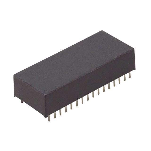
Texas Instruments BQ4013YMA-85
- Part No.:
- BQ4013YMA-85
- Manufacturer:
- Texas Instruments
- Category:
- Memory
- Package:
- 32-DIP Module (0.610", 15.49mm)
- Datasheet:
-
 BQ4013YMA-85.pdf
- Description:
- IC NVSRAM 1MBIT PAR 32DIP MODULE
- Quantity:
- Payment:

- Shipping:

Inventory:2,745
Please send an inquiry. Send us your inquiry, and we will respond immediately.
Product details
Overview
BQ4013YMA-85 from Texas Instruments is a 128 k × 8 (1,048,576-bit) nonvolatile static RAM with integrated lithium backup, 5-V operation, 85 ns access time, and automatic write-protection during power-up/down - deployed in industrial instrumentation for real-time parameter storage across brownout events.
For engineers reviewing the BQ4013YMA-85 datasheet, BQ4013YMA-85 pinout, BQ4013YMA-85 application, or BQ4013YMA-85 equivalent, this page delivers verified timing thresholds (VPFD = 4.37 V), retention duration (≥10 years), DIP-32 package mapping, and functional alternatives for legacy system maintenance and replacement design.
Technical Context
The BQ4013YMA-85 integrates a CMOS SRAM core with on-module lithium coin cell and analog power-fail detection circuitry. It monitors VCC continuously and triggers automatic write-protection when voltage falls below VPFD = 4.37 V (typ), then switches to internal backup supply at VSO ≈ 3 V.
During valid VCC operation, it behaves as a standard asynchronous SRAM with CE/OE/WE control logic and full read/write cycle compatibility. Upon VCC recovery, it enforces tCER = 80 ms (max) write-protection delay to ensure processor stabilization before resuming normal access.
Key Specifications
| Parameter | Value and Actual Design Meaning |
|---|---|
| Memory Density | 128 k × 8 (1,048,576 bits) - supports full byte-wide data storage without external multiplexing. |
| Access Time | 85 ns - enables direct interface with legacy microcontrollers running at ≤12 MHz bus clocks. |
| Supply Voltage | 4.5 V to 5.5 V - compatible with standard 5-V TTL/CMOS systems with ±5% tolerance. |
| Power-Fail Threshold | VPFD = 4.37 V (typ) - calibrated for reliable early detection in 5-V systems with 10% supply variation. |
| Data Retention | ≥10 years without VCC - sustained by isolated lithium cell activated only after first power application. |
| Standby Current | ISB1 = 2 µA max (CE = VIH) - minimizes battery drain during long-term backup mode. |
| Operating Temp | 0 °C to 70 °C - qualified for commercial-grade embedded control and test equipment environments. |
Pinout & Package
Package: 32-pin DIP module (MA package), through-hole mounting, 0.6-inch width, industry-standard footprint compatible with legacy PCB layouts.
| Pin/Terminal | Circuit Role | Design Meaning |
|---|---|---|
| A0–A16 | Address inputs | 17-bit address bus supporting full 128 k-word addressing; A16 is MSB for extended memory maps. |
| DQ0–DQ7 | Data input/output | 8-bit bidirectional data bus; high-impedance during write-protection or chip disable. |
| CE | Chip-enable input | Active-low enable controlling device selection; initiates tCER delay on power-up recovery. |
| OE | Output-enable input | Active-low control for output drivers; allows read-data gating independent of CE state. |
| WE | Write-enable input | Active-low signal qualifying write cycles; held high during read operations. |
| VCC | Supply voltage input | Primary 5-V power rail; monitored for VPFD threshold crossing to trigger backup switchover. |
| VSS | Ground | Reference return path for all digital and analog circuitry including power-fail comparator. |
| NC | No connect | Pins 1 and 30 are unconnected - no internal bonding or routing; must remain floating. |
Key Features
| Feature | Design Value |
|---|---|
| Automatic Power-Fail Write-Protection | Hardware-enforced data lockout triggered at VPFD = 4.37 V, eliminating need for external supervisor ICs or firmware intervention. |
| Integrated Lithium Backup | On-module coin cell electrically isolated until first VCC application - ensures >10-year shelf life and zero self-discharge pre-activation. |
| Standard SRAM Interface | Pin- and timing-compatible with industry-standard 1-Mb SRAMs (e.g., AS6C1008), enabling drop-in replacement in existing designs. |
| Zero External Components Required | Self-contained power monitoring, switching, and retention - no external capacitors, regulators, or battery management circuitry needed. |
| High-Z Output During Fault | All DQ pins enter high-impedance state immediately upon VPFD detection - prevents bus contention during power collapse. |
Applications
| Industrial Data Loggers | Medical Diagnostic Equipment |
|---|---|
|
Use Scenario: Continuous acquisition of sensor readings (temperature, pressure, flow) during mains interruption in portable analyzers. IC Role / Device Role / Timing Role: Nonvolatile scratchpad storing last valid calibration coefficients and timestamped event logs during AC dropout. Use Value: Preserves critical diagnostic history without requiring supercapacitor hold-up or complex power sequencing. |
Use Scenario: Storing patient-specific configuration profiles and runtime error codes in bedside monitors with intermittent power. IC Role / Device Role / Timing Role: Battery-backed SRAM retaining volatile setup data across unplanned shutdowns and transport-induced power loss. Use Value: Eliminates reconfiguration delays and ensures regulatory-compliant audit trail continuity per IEC 62304. |
| Telecom Line Cards | Programmable Logic Controllers |
|
Use Scenario: Maintaining port provisioning tables and alarm status registers during brief utility outages in DSLAM chassis. IC Role / Device Role / Timing Role: Fast-access NVSRAM holding real-time line state and service-level agreement counters. Use Value: Enables sub-100 ms failover response while preserving billing-relevant uptime metrics across power cycles. |
Use Scenario: Saving ladder logic scan states and I/O mapping during factory floor power flickers in automotive assembly PLCs. IC Role / Device Role / Timing Role: Deterministic nonvolatile buffer ensuring deterministic restart from last known-safe scan point. Use Value: Prevents machine motion faults and eliminates manual reset procedures after transient grid disturbances. |
Equivalent & Alternatives
The following parts are listed as comparable options for similar nonvolatile SRAM applications.
| Alternative Part | Technical Difference | Application Difference | Selection Advice |
|---|---|---|---|
| STK13C68-J15F | 128 k × 8 NVSRAM, 150 ns access, 5-V only, no 3.3-V variant; uses capacitor-based backup. | Limited to shorter retention (<5 years); requires external capacitor charging circuit and larger board area. | Prefer where long-term data integrity is secondary to cost-sensitive, low-volume replacements. |
| DS1248W-120+ | 128 k × 8 NVSRAM, 120 ns access, 5-V only, integrated lithium with 10-year retention; different pinout (28-pin SOIC). | Requires PCB redesign due to incompatible DIP-32 footprint and altered address/data pin mapping. | Select only if board revision is feasible and higher temperature range (–40°C to 85°C) is required. |
Compared with BQ4013YMA-85, STK13C68-J15F trades retention longevity for lower bill-of-materials cost, while DS1248W-120+ offers wider temperature support but mandates mechanical redesign - making BQ4013YMA-85 optimal for drop-in maintenance of legacy 5-V DIP-based systems.
Availability
BQ4013YMA-85 is available at Aetrix Electronics and suitable for industrial data loggers, medical diagnostic equipment, telecom line cards, programmable logic controllers, and embedded instrumentation requiring stable component supply amid end-of-life transitions.
Supply support for BQ4013YMA-85 includes scheduled delivery planning, volume procurement assistance, BOM continuity management, traceable sourcing, and lifecycle availability coordination for OEM customers, industrial embedded developers, connected-device designers, and electronics production programs.
Manufacturer
Texas Instruments is a global semiconductor leader delivering analog, embedded processing, and connectivity solutions with emphasis on reliability, longevity, and industrial-grade qualification.
The BQ4013YMA-85 belongs to TI's legacy nonvolatile SRAM product line, engineered specifically for seamless integration into 5-V systems needing guaranteed data retention during unpredictable power loss - targeting instrumentation, telecom infrastructure, and factory automation.
FAQ
What is the guaranteed data retention period for BQ4013YMA-85 under zero-power conditions?
The BQ4013YMA-85 guarantees ≥10 years of data retention without external power, based on TI's characterization of the integrated lithium cell after first activation. This value assumes operation at TA = 25°C and accounts for self-discharge post-isolation break; actual field retention may extend beyond 10 years depending on ambient temperature and usage history. The BQ4013YMA-85 achieves this via factory-isolated battery architecture that minimizes pre-use degradation.
Does BQ4013YMA-85 support 3.3-V operation?
No, BQ4013YMA-85 is specified exclusively for 5-V operation (VCC = 4.5 V to 5.5 V) and uses VPFD = 4.37 V for power-fail detection - optimized for 5-V systems with 10% supply tolerance. For 3.3-V compatibility, TI offers the BQ4013LYMA-70N variant, which has distinct marking, VPFD = 2.90 V, and industrial temperature rating. The BQ4013YMA-85 must not be operated below 4.5 V or above 5.5 V.
What happens to the DQ pins during power-fail detection on BQ4013YMA-85?
When VCC crosses VPFD = 4.37 V downward, the BQ4013YMA-85 immediately places all DQ0–DQ7 pins into high-impedance state to prevent bus contention. Inputs (address, CE, OE, WE) are treated as "don't care", and no further read or write cycles are acknowledged. This behavior is hardware-autonomous and requires no external control - a core safety feature of the BQ4013YMA-85 design.
Is BQ4013YMA-85 pin-compatible with standard 1-Mb SRAMs?
Yes, the BQ4013YMA-85 uses an industry-standard 32-pin DIP pinout matching common 1-Mb SRAMs like the AS6C1008 and CY62128EV30. Address lines A0–A16, data lines DQ0–DQ7, and control signals CE/OE/WE occupy identical positions. This enables direct PCB-level replacement in legacy designs without layout modification - a key advantage of the BQ4013YMA-85 for maintenance upgrades.
What is the purpose of the NC pins on BQ4013YMA-85?
Pins 1 and 30 on the BQ4013YMA-85 are designated NC (No Connect) and contain no internal bonding or electrical connection. They must remain unconnected on the PCB - neither tied to VCC, VSS, nor left floating with pull-ups/downs. TI specifies these pins as mechanically reserved for package integrity and thermal relief; routing or loading them violates the BQ4013YMA-85's validated electrical behavior and may compromise long-term reliability.
BQ4013YMA-85 Specifications
- Product attributes
- Attribute value
- Manufacturer:
- Texas Instruments
- Series:
- -
- Package/Case:
- 32-DIP Module (0.610", 15.49mm)
- Packaging:
- Tube
- Product Status:
- Obsolete
- Programmable:
- Not Verified
- Memory Type:
- Non-Volatile
- Memory Format:
- NVSRAM
- Technology:
- NVSRAM (Non-Volatile SRAM)
- Memory Size:
- 1Mbit
- Memory Organization:
- 128K x 8
- Memory Interface:
- Parallel
- Clock Frequency:
- -
- Write Cycle Time - Word, Page:
- 85ns
- Access Time:
- 85 ns
- Voltage - Supply:
- 4.5V ~ 5.5V
- Operating Temperature:
- 0°C ~ 70°C (TA)
- Grade:
- -
- Qualification:
- -
- Mounting Type:
- Through Hole
- Supplier Device Package:
- 32-DIP Module (18.42x42.8)
BQ4013YMA-85 FAQ
1.How can I place an order for BQ4013YMA-85 through Aetrix?
Please submit a Request for Quotation (RFQ) for BQ4013YMA-85 on Aetrix. Our sales agent will provide a competitive quotation and guide you through the order confirmation once you accept the terms.
2.Are the price and stock information for BQ4013YMA-85 reliable?
The price and inventory of BQ4013YMA-85 are updated periodically and may fluctuate due to market conditions. Stock and pricing data are typically refreshed every 24 hours. Quotation validity for BQ4013YMA-85 is usually 5 days.
3.What payment methods are accepted for BQ4013YMA-85?
We accept Wire Transfer, PayPal, Credit Card, Western Union, MoneyGram, and Escrow for BQ4013YMA-85 transactions.
Note: Certain payment methods may incur a processing fee.
4.How is shipping managed for BQ4013YMA-85?
BQ4013YMA-85 orders can be shipped via leading logistics carriers, including DHL, UPS, FedEx, TNT, or Registered Mail.
Once your BQ4013YMA-85 order is processed, you will receive an email with the shipment details and tracking number.
Note: Tracking information may take up to 24 hours to appear. Express delivery typically takes 3–5 business days.
5.How can I obtain technical support or documentation for BQ4013YMA-85?
For technical support, including BQ4013YMA-85 datasheets, pinout diagrams, or application guidance, please contact our engineering support team. They can provide detailed documentation and assistance for your BQ4013YMA-85 requirements.
6.How does Aetrix verify that BQ4013YMA-85 is sourced from the original manufacturer or authorized distributors?
All BQ4013YMA-85 products on Aetrix are procured from qualified distributors and authorized channels. Our dedicated quality assurance team conducts strict verification, including traceability checks and, if necessary, third-party testing. This ensures that BQ4013YMA-85 meets industry standards.
7.What is the process for return or replacement of BQ4013YMA-85?
All BQ4013YMA-85 units undergo pre-shipment inspection (PSI). If there is an issue with BQ4013YMA-85, returns or replacements are accepted under the following conditions:
1.Quantity discrepancies, incorrect items, or visible external defects (such as breakage or corrosion), acknowledged by Aetrix.
2.The issue is reported within 90 days of delivery.
3.The BQ4013YMA-85 part is unused and in its original packaging.
Return procedure for BQ4013YMA-85:
1.Submit a request within 90 days.
2.Obtain a Return Material Authorization (RMA) from Aetrix.
BQ4013YMA-85 Tags

-
M24C02-WMN6TP
STMicroelectronics

-
AT24C02C-XHM-T
Microchip Technology

-
AT21CS01-STUM10-T
Microchip Technology

-
AT24C02C-SSHM-T
Microchip Technology

-
24LC01BT-I/OT
Microchip Technology

-
M24C02-FMC6TG
STMicroelectronics
-
AT24CS02-SSHM-T
Microchip Technology

-
93LC46BT-I/OT
Microchip Technology
-
AT24C04C-SSHM-T
Microchip Technology

-
24LC01BT-I/SN
Microchip Technology
-
24AA02UIDT-I/OT
Microchip Technology

-
AT24C08C-STUM-T
Microchip Technology
Tech Hub

A practical engineering guide to 3.3V and 5V logic compatibility, input thresholds, resistor dividers, translator ICs, MOSFET level shifting, I2C pull-ups, timing limits and power-sequencing risks.

The 74HC595 uses push-pull logic outputs, while the TPIC6B595 uses 50 V open-drain DMOS sinks for higher-power loads. This guide compares timing, current limits, 3.3 V interfacing, load wiring, thermal…

The 74HC595 converts serial data into eight stable parallel outputs. This guide covers pin functions, shift and storage timing, OE and MR behavior, drive-current limits, cascading, voltage compatibilit…

A technical comparison of level-sensitive latches and edge-triggered flip-flops, covering timing windows, setup and hold limits, master–slave operation, time borrowing, race-through, HDL inference and…

A D latch stores one bit while Enable controls when data can pass. This reference covers gate-level operation, truth tables, transparency, setup and hold timing, LE versus OE, common ICs and practical …

An SR latch stores one bit through cross-coupled feedback. This engineering reference covers NOR and NAND implementations, truth tables, forbidden-state recovery, gated operation, switch debouncing, fa…

Latch circuits retain one bit through feedback. This technical reference covers SR and D latches, truth tables, transparency, timing limits, latch-versus-flip-flop behavior, applications and common log…

An engineering guide to LED driver operation, constant-current and constant-voltage outputs, linear and switching topologies, dimming, IC selection, calculations, replacement compatibility, and fault c…

Operational amplifier guide covering op amp basics, feedback, ideal vs real op amps, common configurations, buffer circuits, offset, bias current, gain-bandwidth, slew rate, rail-to-rail limits and sel…

Jumper cables guide covering safe connection order, red and black clamp placement, final ground connection, cable gauge, length, clamp quality, copper vs CCA cables, jump starter comparison and battery…


