
 My Inquiry
 My Account


Infineon Technologies BTS5662EAUMA1
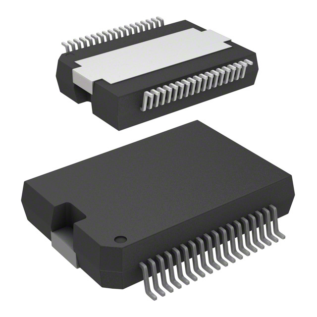
- Part No.:
- BTS5662EAUMA1
- Manufacturer:
- Infineon Technologies
- Category:
- LED Drivers
- Package:
- 36-BSSOP (0.295", 7.50mm Width) Exposed Pad
- Datasheet:
-
 BTS5662EAUMA1.pdf
- Description:
- IC LED DRVR RGLTR SPI 24A 36DSO
- Quantity:
- Payment:

- Shipping:

Inventory:3,870
Please send an inquiry. Send us your inquiry, and we will respond immediately.
Product details
Overview
BTS5662EAUMA1 from Infineon Technologies is a six-channel automotive high-side smart power switch in PG-DSO-36-36 package, designed for 12 V grounded exterior lighting loads. It features SPI-controlled diagnosis, channel-specific current sense multiplexing to IS pin, 100–460 mΩ RDS(ON) (channel-dependent), 5.5–28 V VBB operation, and integrated overtemperature/overload protection. Used in tail light, brake light, and indicator control with fail-safe limp-home activation via LHI pin.
For engineers reviewing the BTS5662EAUMA1 datasheet, BTS5662EAUMA1 pinout, BTS5662EAUMA1 application, or BTS5662EAUMA1 equivalent, this page delivers verified electrical parameters, SPI register mapping context, channel-specific on-resistance grading, daisy-chain SPI capability, and automotive-grade protection behavior - all critical for lamp driver BOM validation and functional safety analysis.
Technical Context
The BTS5662EAUMA1 integrates six N-channel vertical power MOSFETs with charge pumps and monolithic SMART technology, enabling high-side switching without external bootstrap circuitry. Each channel supports independent PWM control via CMOS-compatible INx pins and configurable AND/OR logic combination.
SPI interface operates up to 2 MHz with daisy-chain support, delivering real-time diagnosis including overload/overtemperature flags, multiplexed proportional load current sense (IS), and switch-bypass short-to-VBB detection. Limp-home input (LHI) provides hardware-level fail-safe activation independent of SPI communication.
Key Specifications
| Parameter | Value and Actual Design Meaning |
|---|---|
| VBB Operating Range | 5.5 V to 28 V - supports full automotive battery range including cold-crank (6 V) and load-dump (28 V) conditions |
| RDS(ON) (Ch 0–2) | 100 mΩ max at Tj = 150 °C - enables driving 27 W lamps with ≤1.2 W conduction loss per channel |
| RDS(ON) (Ch 3–4) | 260 mΩ max at Tj = 150 °C - optimized for 10 W auxiliary loads with thermal derating margin |
| RDS(ON) (Ch 5) | 460 mΩ max at Tj = 150 °C - sized for 5 W license plate light with minimal footprint impact |
| Standby Current IBB(OFF) | 3 µA max at 25 °C - ensures negligible battery drain during vehicle sleep mode |
| SPI Clock Frequency | Up to 2 MHz - allows sub-100 µs diagnostic readout across all six channels in daisy-chain configuration |
| Overvoltage Protection | 40 V min VBB(AZ,min) - clamps transients exceeding ISO 7637-2 Pulse 5a without latch-off |
Pinout & Package
Package: PG-DSO-36-36 (exposed thermal pad, 36-pin thermally enhanced SOIC variant). Pin 37 is exposed pad requiring low-impedance connection to VBB for thermal and electrical performance.
| Pin/Terminal | Circuit Role | Design Meaning |
|---|---|---|
| VBB (Pins 19, 36, 37) | High-side power supply input | Pins 19/36 are signal VBB; pin 37 is exposed thermal pad - must be soldered to PCB copper pour tied to VBB |
| VDD (Pin 2) | Logic supply input | 5 V ±10 % supply for internal logic and SPI interface; decoupling capacitor required |
| GND (Pin 1) | Reference ground | Device logic ground - isolated from load ground per channel for ground-referenced lamp topology |
| IN0–IN5 (Pins 7–12) | Parallel channel enable inputs | CMOS-compatible, internally pulled down; direct PWM control without external level shifters |
| OUT0–OUT5 (Pins 16–18, 22–24, 25–26, 27–28, 29–31, 32–34) | Protected high-side outputs | Multi-pin per channel for current sharing and thermal spreading; each output includes integrated current limiting |
| CS, SCLK, SI, SO (Pins 6, 5, 4, 3) | SPI interface signals | Full-duplex 4-wire SPI; CS active-low with internal pull-up; SO supports daisy-chain output forwarding |
| IS (Pin 14) | Multiplexed diagnosis output | Analog current sense signal (proportional to load current); enabled/disabled via SPI command |
| LHI (Pin 13) | Limp-home activation input | Hardware override: active-high signal forces all channels ON regardless of SPI or INx state |
Key Features
| Feature | Design Value |
|---|---|
| Channel-selectable RDS(ON) grading | Three resistance classes (100/260/460 mΩ) match load power tiers: 27 W, 10 W, and 5 W lamps - minimizing die size and thermal stress per channel |
| Daisy-chain SPI architecture | Single SCLK/SI/CS bus controls up to 16 devices; SO of one device connects to SI of next - reduces MCU GPIO count and routing complexity |
| Multiplexed analog current sense (IS) | Per-channel proportional current monitoring with <±5 % accuracy across 10 mA–3 A range - enables closed-loop brightness calibration without external shunts |
| Fail-safe limp-home activation (LHI) | Hardware-level override that bypasses all digital logic and protection states - ensures critical lighting remains ON during ECU failure |
| Loss-of-ground and loss-of-VBB detection | Dedicated diagnostics flag in SPI status word - identifies open-circuit faults in power path before thermal runaway occurs |
Applications
| Rear Combination Lamp Control | Front Parking & Position Light |
|---|---|
|
Use Scenario: Driving tail light, brake light, reverse light, and turn indicators from a single ECU node in compact rear lamp housing. IC Role / Device Role / Timing Role: Six-channel high-side switch managing independent ON/OFF and PWM dimming per function, with real-time thermal and short-circuit feedback. Use Value: Replaces six discrete relays and fuses; eliminates mechanical wear, contact bounce, and fuse replacement while enabling diagnostics via IS and SPI. |
Use Scenario: Controlling dual-filament parking lights and LED position lights on vehicle front fascia with shared ECU resources. IC Role / Device Role / Timing Role: High-side driver with graded RDS(ON) - lower-resistance channels drive 27 W filaments, higher-resistance channels drive 5 W LEDs. Use Value: Eliminates need for separate drivers per lamp type; integrated overvoltage protection withstands 40 V load-dump transients without external TVS. |
| License Plate Illumination | Turn Signal Flasher Interface |
|
Use Scenario: Powering 5 W white LED array behind translucent license plate cover with ambient temperature up to 85 °C. IC Role / Device Role / Timing Role: Dedicated Ch5 (460 mΩ) supplies constant current with thermal foldback - maintains illumination during prolonged daytime operation. Use Value: No external current-setting resistor needed; built-in thermal shutdown prevents LED degradation under sustained thermal stress. |
Use Scenario: Interfacing with CAN-based body controller to implement variable-frequency flashing (e.g., hazard vs. turn) using PWM on INx pins. IC Role / Device Role / Timing Role: SPI-configurable AND/OR logic on parallel inputs allows synchronized multi-channel flash patterns without MCU firmware changes. Use Value: Enables flash pattern reconfiguration via diagnostic tool - no hardware modification required for regional compliance updates. |
Equivalent & Alternatives
The following parts are listed as comparable options for similar high-side smart power switch applications.
| Alternative Part | Technical Difference | Application Difference | Selection Advice |
|---|---|---|---|
| BTS5660E | Single-chip 6-channel device with identical pinout but no LHI pin and reduced RDS(ON) grading (all channels 100 mΩ) | Lacks hardware limp-home override; less optimal for mixed-load applications requiring differentiated channel resistance | Select when only uniform 27 W lamp driving is needed and fail-safe hardware override is not required |
| TPS4H160-Q1 | TI 4-channel high-side switch with 120 mΩ RDS(ON), SPI + parallel control, but no multiplexed IS pin or daisy-chain support | Requires two ICs for six channels; lacks per-channel current sense and short-to-VBB diagnosis | Select when design prioritizes TI ecosystem compatibility and simpler SPI protocol over advanced diagnostics |
Compared with BTS5662EAUMA1, BTS5660E sacrifices limp-home safety and load-matching RDS(ON) grading for cost reduction, while TPS4H160-Q1 trades channel count and diagnostic depth for broader voltage tolerance (4.5–36 V) and faster fault response.
Availability
BTS5662EAUMA1 is available at Aetrix Electronics and suitable for automotive lighting control, body electronics modules, and chassis domain controllers requiring stable component supply, AEC-Q100 Grade 1 qualification, and long-term production continuity.
Supply support for BTS5662EAUMA1 includes scheduled delivery planning, volume procurement assistance, BOM continuity management, traceable sourcing, and lifecycle availability coordination for OEM customers, industrial embedded developers, connected-device designers, and electronics production programs.
Manufacturer
Infineon Technologies is a German semiconductor manufacturer specializing in power management, automotive ICs, and industrial control solutions, with global manufacturing and automotive qualification infrastructure.
The SPOC (Smart Power Octal/Hexa) product line delivers integrated high-side switches with embedded protection and diagnostics - engineered specifically for replacing electromechanical relays in 12 V automotive lighting and body control applications.
FAQ
What is the maximum continuous current per channel for BTS5662EAUMA1?
Maximum continuous current depends on channel and thermal conditions: Channel 0–2 supports up to 3.5 A, Channel 3–4 up to 2.2 A, and Channel 5 up to 1.5 A at Tj = 150 °C with adequate PCB copper area. These limits derive from RDS(ON) grading and thermal resistance of the PG-DSO-36-36 package, validated per AEC-Q100 transient thermal testing.
Does BTS5662EAUMA1 require external components for reverse polarity protection?
Yes - reverse battery protection requires external components: a series Schottky diode between battery and VBB, plus optional RC snubber. The datasheet specifies this in Section 7.3 and Figure 13; the IC itself does not integrate reverse-polarity MOSFET control or internal diode clamping.
Can the IS (diagnosis) pin output be used for closed-loop current regulation?
No - the IS pin provides a multiplexed analog voltage proportional to load current (typically 1 mV/mA), but it is not intended for real-time feedback control due to multiplexing delay (~10 µs per channel) and lack of dedicated error amplifier. It is specified for diagnostic logging and fault detection only.
How does the LHI (limp home) pin interact with SPI-controlled channel states?
The LHI pin is a hardware override: when driven high, it forces all six channels into ON state regardless of SPI register settings, INx pin levels, or active protection faults. This behavior is asynchronous and cannot be disabled via software - ensuring fail-operational lighting during ECU communication loss.
BTS5662EAUMA1 Specifications
- Product attributes
- Attribute value
- Manufacturer:
- Infineon Technologies
- Series:
- -
- Package/Case:
- 36-BSSOP (0.295", 7.50mm Width) Exposed Pad
- Packaging:
- Tape & Reel (TR)
- Product Status:
- Obsolete
- Type:
- DC DC Regulator
- Topology:
- Switched Capacitor (Charge Pump)
- Internal Switch(s):
- Yes
- Number of Outputs:
- 6
- Voltage - Supply (Min):
- 5.5V
- Voltage - Supply (Max):
- 28V
- Voltage - Output:
- -
- Current - Output / Channel:
- 24A
- Frequency:
- 2MHz
- Dimming:
- SPI
- Applications:
- -
- Operating Temperature:
- -40°C ~ 150°C (TJ)
- Grade:
- Automotive
- Qualification:
- -
- Mounting Type:
- Surface Mount
- Supplier Device Package:
- PG-DSO-36-36
BTS5662EAUMA1 FAQ
1.How can I place an order for BTS5662EAUMA1 through Aetrix?
Please submit a Request for Quotation (RFQ) for BTS5662EAUMA1 on Aetrix. Our sales agent will provide a competitive quotation and guide you through the order confirmation once you accept the terms.
2.Are the price and stock information for BTS5662EAUMA1 reliable?
The price and inventory of BTS5662EAUMA1 are updated periodically and may fluctuate due to market conditions. Stock and pricing data are typically refreshed every 24 hours. Quotation validity for BTS5662EAUMA1 is usually 5 days.
3.What payment methods are accepted for BTS5662EAUMA1?
We accept Wire Transfer, PayPal, Credit Card, Western Union, MoneyGram, and Escrow for BTS5662EAUMA1 transactions.
Note: Certain payment methods may incur a processing fee.
4.How is shipping managed for BTS5662EAUMA1?
BTS5662EAUMA1 orders can be shipped via leading logistics carriers, including DHL, UPS, FedEx, TNT, or Registered Mail.
Once your BTS5662EAUMA1 order is processed, you will receive an email with the shipment details and tracking number.
Note: Tracking information may take up to 24 hours to appear. Express delivery typically takes 3–5 business days.
5.How can I obtain technical support or documentation for BTS5662EAUMA1?
For technical support, including BTS5662EAUMA1 datasheets, pinout diagrams, or application guidance, please contact our engineering support team. They can provide detailed documentation and assistance for your BTS5662EAUMA1 requirements.
6.How does Aetrix verify that BTS5662EAUMA1 is sourced from the original manufacturer or authorized distributors?
All BTS5662EAUMA1 products on Aetrix are procured from qualified distributors and authorized channels. Our dedicated quality assurance team conducts strict verification, including traceability checks and, if necessary, third-party testing. This ensures that BTS5662EAUMA1 meets industry standards.
7.What is the process for return or replacement of BTS5662EAUMA1?
All BTS5662EAUMA1 units undergo pre-shipment inspection (PSI). If there is an issue with BTS5662EAUMA1, returns or replacements are accepted under the following conditions:
1.Quantity discrepancies, incorrect items, or visible external defects (such as breakage or corrosion), acknowledged by Aetrix.
2.The issue is reported within 90 days of delivery.
3.The BTS5662EAUMA1 part is unused and in its original packaging.
Return procedure for BTS5662EAUMA1:
1.Submit a request within 90 days.
2.Obtain a Return Material Authorization (RMA) from Aetrix.
BTS5662EAUMA1 Tags

-
BCR402RE6327HTSA1
Infineon Technologies

-
BCR430UXTSA2
Infineon Technologies

-
BCR420UE6433HTMA1
Infineon Technologies
-
BCR420UE6327HTSA1
Infineon Technologies
-
BCR421UE6327HTSA1
Infineon Technologies

-
LYT1604D-TL
Power Integrations

-
HV9910CLG-G
Microchip Technology

-
CL2N8-G
Microchip Technology

-
BCR420UW6-7
Diodes Incorporated
-
BCR421UW6-7
Diodes Incorporated

-
BCR420UFD-7
Diodes Incorporated
-
BCR421UFD-7
Diodes Incorporated
Tech Hub

An engineering guide to LED driver operation, constant-current and constant-voltage outputs, linear and switching topologies, dimming, IC selection, calculations, replacement compatibility, and fault c…

Operational amplifier guide covering op amp basics, feedback, ideal vs real op amps, common configurations, buffer circuits, offset, bias current, gain-bandwidth, slew rate, rail-to-rail limits and sel…

Jumper cables guide covering safe connection order, red and black clamp placement, final ground connection, cable gauge, length, clamp quality, copper vs CCA cables, jump starter comparison and battery…

LDO regulator guide covering low dropout voltage, power dissipation, thermal design, PSRR, output noise, capacitor stability, adjustable LDO circuits, LDO vs buck converter and datasheet selection chec…

Conditional Access Module guide covering CAM meaning, CI/CI+ interface, smart card authorization, DVB security workflow, TV and set-top box compatibility, internal electronics, ESD protection, connecto…

Guide to electronic component obsolescence covering EOL risk, PCN/PDN notices, last-time buy planning, replacement options, form-fit-function validation, counterfeit risk and BOM lifecycle management.

18650 battery guide covering lithium-ion cell basics, 3.6V/3.7V voltage, 4.2V charging, mAh and Wh capacity, protected cells, chargers, BMS, series-parallel packs, holders, welding and sourcing checks.…

Hall effect sensor guide covering working principle, linear and digital sensors, Arduino circuits, current sensing, speed detection, automotive applications, A3144 examples, signal filtering and datash…

Product Change Notification guide for electronic components, covering PCN meaning, PCN vs PDN/EOL, common change types, risk levels, form-fit-function review, engineering validation, BOM control, LTB/L…

A practical guide to blend door actuators, covering HVAC function, symptoms, location, AC and heater issues, reset and calibration, replacement cost, electrical diagnosis, compatibility checks, and rep…


