Send an Inquiry

To receive a quote for your project, please fill in the following information, and we’ll get back to you promptly.

Name*
Company*
Email Address*
Phone/WhatsApp
Part Number*
Quantity*
Message
Submit Inventory List

Please fill in the following information, and we’ll get back to you promptly.

Name*
Company*
Email Address*
Phone/WhatsApp
Upload My List
Message

Vishay General Semiconductor - Diodes Division BYS10-35HE3/TR3

Part No.:
BYS10-35HE3/TR3
Manufacturer:
Vishay General Semiconductor - Diodes Division
Category:
Single Diodes
Package:
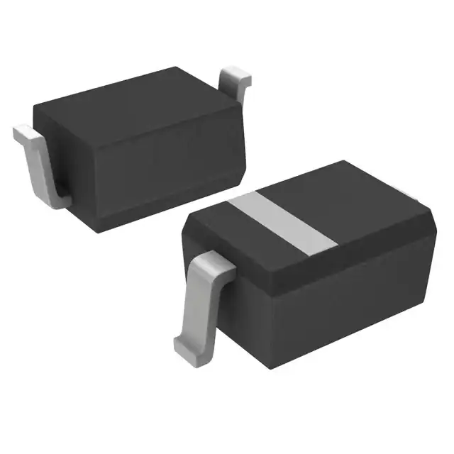
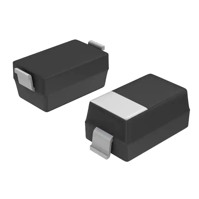
DO-214AC, SMA
Datasheet:
AetrixBYS10-35HE3/TR3.pdf
Description:
DIODE SCHOTTKY 35V 1.5A DO214AC
Quantity:
Payment:
Payment
Shipping:
Shipping

Inventory:6,859

Please send an inquiry. Send us your inquiry, and we will respond immediately.

Part Number
Quantity*
Price
Name*
Company
Email*
Comments

Product details

Overview

BYS10-35HE3/TR3 from Vishay General Semiconductor is a surface-mount Schottky barrier rectifier in SMA (DO-214AC) package, rated for 35 V maximum repetitive peak reverse voltage, 1.5 A average forward current, and 40 A peak surge current. It delivers 500 mV forward voltage at 1.0 A and operates from –65 °C to +150 °C junction temperature, serving as a low-loss freewheeling or polarity protection diode in DC/DC converters.

For engineers reviewing the BYS10-35HE3/TR3 datasheet, BYS10-35HE3/TR3 pinout, BYS10-35HE3/TR3 application, or BYS10-35HE3/TR3 equivalent, key selection criteria include its AEC-Q101 qualification, 25 °C/W junction-to-lead thermal resistance, MSL Level 1 rating, matte tin-plated terminals, and guardring-enabled overvoltage protection - all critical for automotive and high-reliability power conversion designs.

Technical Context

This Schottky rectifier uses a planar epitaxial construction with integrated guardring to suppress edge breakdown and improve ruggedness under transient overvoltage conditions. Its low 500 mV VF at 1.0 A and negligible reverse recovery charge enable high-efficiency operation in high-frequency switching topologies up to several hundred kHz.

The device is optimized for automated SMT assembly on FR-4 PCBs with standard reflow profiles (peak 260 °C), supported by J-STD-002–compliant solderability and JESD201 Class 2 whisker resistance. Thermal performance is characterized with RθJL = 25 °C/W and RθJA = 100–150 °C/W depending on copper pad area and substrate material.

Key Specifications

ParameterValue and Actual Design Meaning
VRRM35 V - Maximum reverse blocking capability without breakdown; defines usable input voltage range in buck or flyback secondary-side rectification.
IF(AV)1.5 A - Continuous DC forward current rating at TA = 75 °C on 50 mm² Cu pad; sets baseline output current capacity in DC/DC converters.
VF @ 1.0 A500 mV - Low conduction loss ensures >92 % efficiency in 3.3–5 V output stages at moderate load.
IFSM40 A - Peak non-repetitive surge current handling for 8.3 ms half-sine; supports startup inrush and fault-current tolerance.
TJ max.+150 °C - Maximum junction temperature enables operation in under-hood automotive environments without derating.
RθJL25 °C/W - Low junction-to-lead thermal resistance allows effective heat transfer to PCB copper, reducing thermal stress during sustained load.
AEC-Q101Qualified - Meets stress test requirements for automotive electronics, including temperature cycling, HTRB, and ESD.

Pinout & Package

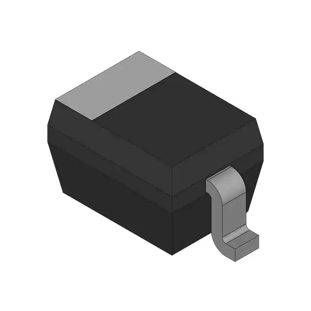
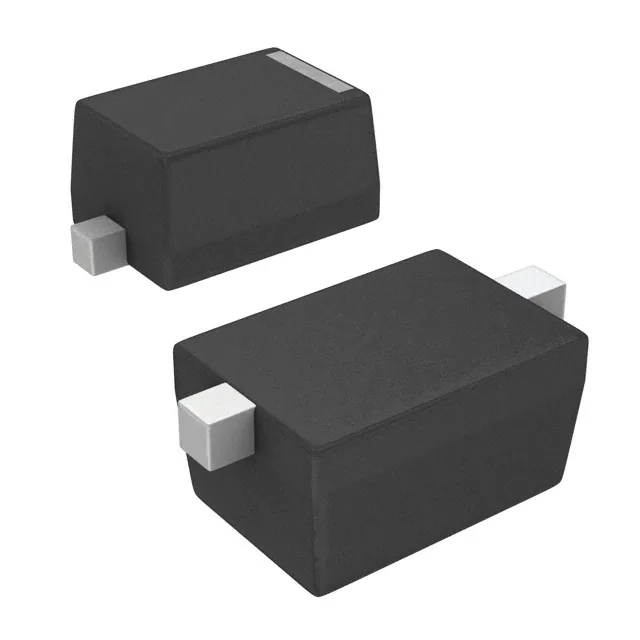
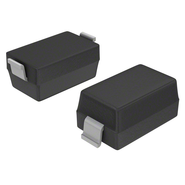
Package: SMA (DO-214AC), surface-mount, single-diode configuration with cathode band marking. Dimensions: 4.93 mm × 3.99 mm × 2.29 mm (L × W × H); molded compound meets UL 94 V-0.

Pin/TerminalCircuit RoleDesign Meaning
AnodeForward current entry pointConnected to lower-potential node (e.g., switch node in synchronous buck); must be routed with low-inductance trace for high-frequency stability.
CathodeForward current exit / reverse voltage referenceMarked with color band; ties to output rail or ground return path; determines polarity protection direction and freewheeling loop closure.

Key Features

FeatureDesign Value
Guardring structurePrevents premature edge breakdown under high dv/dt or reverse transients, improving reliability in noisy automotive power nets.
Low VF (500 mV @ 1 A)Reduces conduction loss by ~40 % vs. comparable silicon PN rectifiers, directly increasing converter efficiency and lowering thermal load.
MSL Level 1 ratingEnables unlimited floor life and standard reflow without baking, simplifying manufacturing logistics and reducing process risk.
AEC-Q101 qualificationValidates suitability for automotive body control modules, infotainment power supplies, and ADAS subsystems requiring long-term field reliability.
Matte tin-plated leadsEnsures consistent solder wetting and joint integrity across lead-free reflow profiles per J-STD-002 and JESD22-B102.

Applications

Automotive Body Control Module (BCM)USB-C Power Delivery Adapter

Use Scenario: Reverse polarity and load dump protection in 12 V supply rails feeding microcontrollers and CAN transceivers.

IC Role / Device Role / Timing Role: Polarity protection diode placed upstream of LDOs and PMICs; blocks reverse battery connection and clamps transients via guardring-enhanced ruggedness.

Use Value: Prevents system damage during jump-start misconnection while maintaining <500 mV drop at 1.5 A, minimizing voltage headroom loss.

Use Scenario: Secondary-side synchronous rectification in 20–65 W USB PD flyback converters operating at 100–300 kHz.

IC Role / Device Role / Timing Role: Freewheeling Schottky rectifier replacing MOSFET gate drive complexity; leverages zero reverse recovery for clean turn-off.

Use Value: Enables >94 % efficiency at 5 V/3 A output with no reverse recovery spikes, reducing EMI filter burden and enabling smaller magnetics.

Industrial DC/DC ConverterSmart Home Hub Power Supply

Use Scenario: Output rectification in isolated 24 V input → 5 V/3.3 V DC/DC modules used in PLC I/O modules and sensor interfaces.

IC Role / Device Role / Timing Role: Primary output rectifier in continuous-conduction-mode flyback; handles 1.5 A average load with minimal thermal rise on 50 mm² Cu.

Use Value: Delivers stable 5 V output with <0.5 °C/W effective thermal resistance when mounted on recommended pad layout, supporting fanless enclosure design.

Use Scenario: Input polarity protection and hold-up rectification in dual-input (USB + wall adapter) power management for Wi-Fi/BLE hubs.

IC Role / Device Role / Timing Role: OR-ing diode between two 5 V sources; selects higher-voltage rail while blocking backfeed using low VF and fast switching.

Use Value: Achieves <100 mV dropout difference between inputs, enabling seamless source switchover without brownout or reset events.

Equivalent & Alternatives

The following parts are listed as comparable options for similar Schottky rectifier applications.

Alternative PartTechnical DifferenceApplication DifferenceSelection Advice
SS13HE3/TR3Same SMA package, 30 V VRRM, 1.3 A IF(AV), 450 mV VF @ 1 A, not AEC-Q101 qualifiedLimited to commercial-grade 3.3–5 V systems; unsuitable for automotive due to missing qualification and lower surge ratingSelect when cost sensitivity outweighs automotive compliance and 35 V margin is unnecessary.
SB130HE3/TR3SMA package, 30 V VRRM, 1.0 A IF(AV), 550 mV VF @ 1 A, AEC-Q101 qualifiedLower current rating restricts use to sub-1 A loads; higher VF increases conduction loss in high-duty-cycle appsChoose only for space-constrained AEC-Q101 designs where 1.0 A is sufficient and 35 V margin is not required.

Compared with SS13HE3/TR3 and SB130HE3/TR3, BYS10-35HE3/TR3 uniquely combines 35 V blocking, 1.5 A average current, AEC-Q101 qualification, and 500 mV VF - making it the only option among the three suitable for 12 V automotive DC/DC outputs requiring both surge robustness and thermal headroom.

Availability

BYS10-35HE3/TR3 is available at Aetrix Electronics and suitable for automotive body control modules, USB-C power delivery adapters, and industrial DC/DC converters requiring stable component supply, AEC-Q101 compliance, and high-reliability Schottky performance.

Supply support for BYS10-35HE3/TR3 includes scheduled delivery planning, volume procurement assistance, BOM continuity management, traceable sourcing, and lifecycle availability coordination for OEM customers, industrial embedded developers, connected-device designers, and electronics production programs.

Manufacturer

Vishay General Semiconductor is a global leader in discrete semiconductors, specializing in diodes, rectifiers, MOSFETs, and optoelectronics with emphasis on reliability, efficiency, and automotive-grade validation.

The BYS10 series targets high-frequency, low-loss power conversion in space-constrained applications - designed specifically for automotive and industrial DC/DC, freewheeling, and polarity protection where thermal performance and transient ruggedness are critical.

FAQ

What is the maximum junction temperature rating for BYS10-35HE3/TR3?

The BYS10-35HE3/TR3 has a maximum junction temperature (TJ max.) of +150 °C, verified per Vishay's datasheet revision 13-May-2020. This rating enables reliable operation in under-hood automotive environments and thermally dense industrial PCB layouts. Derating curves in Figure 3 confirm 1.5 A IF(AV) is maintainable up to 75 °C ambient when mounted on 50 mm² copper, and BYS10-35HE3/TR3 remains within safe operating limits even during short-term transients near its thermal limit.

Is BYS10-35HE3/TR3 suitable for automotive applications?

Yes, BYS10-35HE3/TR3 is AEC-Q101 qualified, as explicitly stated in the Vishay datasheet under "Mechanical Data" and "Ordering Information." The HE3 suffix denotes RoHS-compliant and AEC-Q101–qualified versions. BYS10-35HE3/TR3 passes stress tests including temperature cycling, high-temperature reverse bias (HTRB), and electrostatic discharge - making it appropriate for automotive body control modules, infotainment power supplies, and ADAS subsystems where long-term field reliability is mandatory.

What does the "TR3" suffix indicate in BYS10-35HE3/TR3?

The "TR3" suffix in BYS10-35HE3/TR3 specifies packaging: 13-inch diameter plastic tape and reel, with a base quantity of 7500 units per reel. This format is optimized for high-volume SMT placement equipment. The TR3 designation is distinct from TR (7-inch reel, 1800 units) and H/I variants; all share identical electrical and thermal specifications. BYS10-35HE3/TR3 maintains full compatibility with standard pick-and-place feeders calibrated for DO-214AC devices.

How does the guardring feature benefit BYS10-35HE3/TR3 in real-world circuits?

The guardring in BYS10-35HE3/TR3 suppresses edge breakdown during high dv/dt transients - such as load dump pulses in automotive 12 V systems - by redistributing electric field stress away from the semiconductor periphery. This improves ruggedness without increasing VF or leakage, allowing BYS10-35HE3/TR3 to sustain reverse surges beyond its rated VRRM without failure. In practice, this extends service life in noisy power rails where unguarded Schottky diodes would degrade prematurely.

What is the thermal resistance from junction to ambient for BYS10-35HE3/TR3 under standard mounting conditions?

BYS10-35HE3/TR3 has a maximum junction-to-ambient thermal resistance (RθJA) of 150 °C/W when mounted on epoxy-glass hard tissue (no copper pour), 125 °C/W on 50 mm² 35 μm Cu, and 100 °C/W on Al₂O₃ ceramic with same copper area. These values are measured per JEDEC standards and define thermal design margins: for example, at 1.5 A and 500 mV VF, BYS10-35HE3/TR3 dissipates 0.75 W - resulting in ≤75 °C rise above ambient on 50 mm² Cu, well within its +150 °C TJ limit.

BYS10-35HE3/TR3 Specifications

Product attributes
Attribute value
Manufacturer:
Vishay General Semiconductor - Diodes Division
Series:
-
Package/Case:
DO-214AC, SMA
Packaging:
Tape & Reel (TR)
Product Status:
Discontinued at Digi-Key
Technology:
Schottky
Voltage - DC Reverse (Vr) (Max):
35 V
Current - Average Rectified (Io):
1.5A
Voltage - Forward (Vf) (Max) @ If:
500 mV @ 1 A
Speed:
Fast Recovery =< 500ns, > 200mA (Io)
Reverse Recovery Time (trr):
-
Current - Reverse Leakage @ Vr:
500 µA @ 35 V
Capacitance @ Vr, F:
-
Grade:
-
Qualification:
-
Mounting Type:
Surface Mount
Supplier Device Package:
DO-214AC (SMA)
Operating Temperature - Junction:
-65°C ~ 150°C

BYS10-35HE3/TR3 FAQ

1.How can I place an order for BYS10-35HE3/TR3 through Aetrix?

Please submit a Request for Quotation (RFQ) for BYS10-35HE3/TR3 on Aetrix. Our sales agent will provide a competitive quotation and guide you through the order confirmation once you accept the terms.

2.Are the price and stock information for BYS10-35HE3/TR3 reliable?

The price and inventory of BYS10-35HE3/TR3 are updated periodically and may fluctuate due to market conditions. Stock and pricing data are typically refreshed every 24 hours. Quotation validity for BYS10-35HE3/TR3 is usually 5 days.

3.What payment methods are accepted for BYS10-35HE3/TR3?

We accept Wire Transfer, PayPal, Credit Card, Western Union, MoneyGram, and Escrow for BYS10-35HE3/TR3 transactions.

Note: Certain payment methods may incur a processing fee.

4.How is shipping managed for BYS10-35HE3/TR3?

BYS10-35HE3/TR3 orders can be shipped via leading logistics carriers, including DHL, UPS, FedEx, TNT, or Registered Mail.

Once your BYS10-35HE3/TR3 order is processed, you will receive an email with the shipment details and tracking number.

Note: Tracking information may take up to 24 hours to appear. Express delivery typically takes 3–5 business days.

5.How can I obtain technical support or documentation for BYS10-35HE3/TR3?

For technical support, including BYS10-35HE3/TR3 datasheets, pinout diagrams, or application guidance, please contact our engineering support team. They can provide detailed documentation and assistance for your BYS10-35HE3/TR3 requirements.

6.How does Aetrix verify that BYS10-35HE3/TR3 is sourced from the original manufacturer or authorized distributors?

All BYS10-35HE3/TR3 products on Aetrix are procured from qualified distributors and authorized channels. Our dedicated quality assurance team conducts strict verification, including traceability checks and, if necessary, third-party testing. This ensures that BYS10-35HE3/TR3 meets industry standards.

7.What is the process for return or replacement of BYS10-35HE3/TR3?

All BYS10-35HE3/TR3 units undergo pre-shipment inspection (PSI). If there is an issue with BYS10-35HE3/TR3, returns or replacements are accepted under the following conditions:

1.Quantity discrepancies, incorrect items, or visible external defects (such as breakage or corrosion), acknowledged by Aetrix.

2.The issue is reported within 90 days of delivery.

3.The BYS10-35HE3/TR3 part is unused and in its original packaging.

Return procedure for BYS10-35HE3/TR3:

1.Submit a request within 90 days.

2.Obtain a Return Material Authorization (RMA) from Aetrix.

BYS10-35HE3/TR3 Tags
  • BYS10-35HE3/TR3
  • BYS10-35HE3/TR3 PDF
  • BYS10-35HE3/TR3 Datasheet
  • BYS10-35HE3/TR3 Specifications
  • BYS10-35HE3/TR3 Images
  • Vishay General Semiconductor - Diodes Division
  • Vishay General Semiconductor - Diodes Division BYS10-35HE3/TR3
  • Buy BYS10-35HE3/TR3
  • BYS10-35HE3/TR3 Price
  • BYS10-35HE3/TR3 Distributor
  • BYS10-35HE3/TR3 Supplier
  • BYS10-35HE3/TR3 Wholesale
Related Products
1N4448X-TP
1N4448X-TP

Micro Commercial Co

1N4148WX-TP
1N4148WX-TP

Micro Commercial Co

1N4148TR
1N4148TR

onsemi

MMSD4148T1G
MMSD4148T1G

onsemi

MMBD914LT3G
MMBD914LT3G

onsemi

BAS16HT1G
BAS16HT1G

onsemi

1N914BWT
1N914BWT

onsemi

BAS21LT1G
BAS21LT1G

onsemi

LL4148
LL4148

onsemi

BAS16LT1G
BAS16LT1G

onsemi

MMSD914T1G
MMSD914T1G

onsemi

BAV21W-7-F
BAV21W-7-F

Diodes Incorporated

Tech Hub

Search

Search

PRODUCT

PRODUCT

PHONE

PHONE

USER

USER