
 My Inquiry
 My Account


onsemi CAT810LSDI-T3
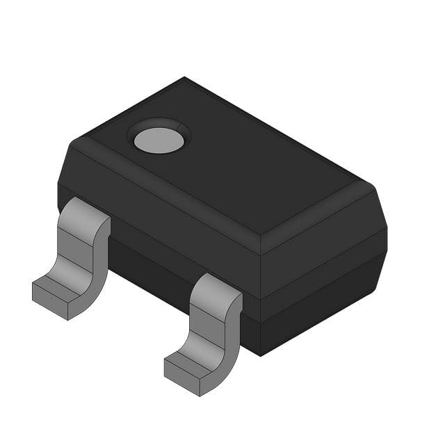
- Part No.:
- CAT810LSDI-T3
- Manufacturer:
- onsemi
- Category:
- Supervisors
- Package:
- SC-70, SOT-323
- Datasheet:
-
 CAT810LSDI-T3.pdf
- Description:
- IC SUPERVISOR 1 CHANNEL SC70-3
- Quantity:
- Payment:

- Shipping:

Inventory:3,824
Please send an inquiry. Send us your inquiry, and we will respond immediately.
Product details
Overview
CAT810LSDI-T3 from onsemi is a 3-pin push-pull active HIGH microprocessor power supply supervisor designed for precision reset generation in digital systems. It monitors +4.63 V supplies with ±5% threshold accuracy, asserts RESET high during undervoltage conditions, and guarantees valid output down to VCC = 1.0 V. Its 140–460 ms reset timeout and 6 µA supply current support reliable boot sequencing in industrial embedded controllers.
For engineers reviewing the CAT810LSDI-T3 datasheet, pinout, applications, or equivalent options, this page delivers verified electrical parameters, SC-70 package details, reset timing behavior, and direct alternatives for industrial-grade power monitoring designs requiring stable active-HIGH reset assertion.
Technical Context
The CAT810LSDI-T3 implements a precision bandgap voltage reference and comparator to detect VCC falling below 4.63 V (±5% over −40°C to +85°C), triggering an active-HIGH RESET signal. Its internal digital delay circuit enforces a minimum 140 ms reset pulse width after VCC recovers above threshold.
It features transient immunity against fast VCC dips ≤100 mV amplitude and ≤4 µs duration, and maintains defined RESET logic state even when VCC drops as low as 1.0 V-requiring only an external pull-up resistor to VCC for guaranteed high-level assertion under brownout.
Key Specifications
| Parameter | Value and Actual Design Meaning |
|---|---|
| Reset Threshold | 4.63 V ±5% at +25°C; ensures reliable detection of +5 V rail undervoltage before system instability occurs |
| Reset Timeout | 140–460 ms; provides sufficient hold time for CPU/MCU core initialization and peripheral stabilization |
| Supply Current | 6 µA typical; enables ultra-low-power operation in battery-backed or energy-sensitive applications |
| VCC Operating Range | 1.2–5.5 V (−40°C to +85°C); supports operation during deep brownout and full-rail startup |
| RESET Output Type | Push-pull active HIGH; eliminates need for external pull-up in most host interfaces and drives CMOS inputs directly |
| Reset Valid Down To | VCC = 1.0 V; guarantees known logic state during severe supply collapse, preventing metastability |
| Tempco | 30 ppm/°C; limits threshold drift to <±20 mV across full industrial temperature range |
Pinout & Package
Package: SC-70-3 (Case 419AB), 1.25 mm × 2.0 mm footprint, surface-mount, RoHS-compliant matte-tin lead finish.
| Pin/Terminal | Circuit Role | Design Meaning |
|---|---|---|
| 1 (GND) | Ground reference | Return path for internal bias and comparator; must be low-impedance connection to system ground plane |
| 2 (RESET) | Active-HIGH reset output | Push-pull CMOS output; sources current when asserted high; sinks current when deasserted low; requires no external pull-up for basic operation |
| 3 (VCC) | Monitored power supply input | Primary supply rail being supervised; powers internal circuitry and sets reference point for threshold detection |
Key Features
| Feature | Design Value |
|---|---|
| Precision 4.63 V threshold | ±5% tolerance over −40°C to +85°C ensures consistent reset activation across industrial environments |
| Active-HIGH push-pull RESET | Direct CMOS-compatible interface eliminates external pull-up resistor and reduces BOM count |
| 140 ms minimum reset timeout | Guarantees sufficient reset hold time for ARM Cortex-M, PIC, and 8051-based microcontrollers during cold start |
| Valid RESET at VCC ≥ 1.0 V | Prevents undefined reset state during brownout recovery, enabling deterministic power-fail response |
| Transient immunity | Rejects VCC glitches ≤100 mV / ≤4 µs-critical for noisy switch-mode power supply environments |
Applications
| Industrial PLC Controllers | Smart Energy Meters |
|---|---|
Use Scenario: Power-on reset and brownout detection in DIN-rail mounted programmable logic controllers operating in factory-floor environments with fluctuating 24 V DC supplies. IC Role / Device Role / Timing Role: Supervises 5 V local regulation derived from 24 V input; generates clean, glitch-free active-HIGH reset pulse synchronized to VCC rise. Use Value: Prevents firmware lockup during line transients and ensures deterministic boot sequence after power interruption. |
Use Scenario: Reset management in Class 0.5S electricity meters exposed to wide ambient temperatures and conducted EMI from grid-connected inverters. IC Role / Device Role / Timing Role: Monitors isolated 5 V auxiliary rail; asserts active-HIGH RESET to MCU and metrology ASIC upon undervoltage event. Use Value: Maintains meter data integrity by forcing controlled reboot before analog front-end corruption occurs. |
| Network Edge Routers | Medical Diagnostic Handhelds |
Use Scenario: Cold-start supervision in fanless enterprise routers using multi-rail PMICs where 5 V main rail powers CPU, PHY, and memory subsystems. IC Role / Device Role / Timing Role: Provides synchronized active-HIGH reset to SoC and Ethernet PHYs; tolerates 1.0 V VCC during partial rail collapse. Use Value: Eliminates race conditions between power rails and prevents partial initialization that causes link flapping or packet loss. |
Use Scenario: Battery-powered ultrasound probe with dual 3.3 V/5 V rails, requiring fail-safe reset during Li-ion discharge below 3.2 V. IC Role / Device Role / Timing Role: Supervises 5 V rail generated from boost converter; asserts active-HIGH RESET to ARM Cortex-A7 processor and ADC controller. Use Value: Ensures diagnostic image acquisition halts cleanly before voltage sag corrupts analog sampling or flash writes. |
Equivalent & Alternatives
The following parts are listed as comparable options for similar power supply supervisor applications.
| Alternative Part | Technical Difference | Application Difference | Selection Advice |
|---|---|---|---|
| MAX810LUR+T | Same 4.63 V threshold, SOT-23-3 package, but open-drain active-LOW output; requires external pull-up and inverted logic handling | Requires PCB-level inversion or firmware adaptation for active-HIGH reset signaling | Select only if legacy MAX810 compatibility is mandatory and system design accommodates active-LOW assertion |
| TPS3808G15DBVR | Adjustable threshold (via external resistor), 1.5% accuracy, 360 ms fixed timeout, 1.8–6 V VCC range | Supports custom thresholds and wider input voltage range but lacks guaranteed 1.0 V reset validity | Choose when precise threshold tuning or extended VCC range is needed, accepting trade-off in brownout-state reliability |
Compared with CAT810LSDI-T3, MAX810LUR+T demands logic inversion and adds external components, while TPS3808G15DBVR offers flexibility at the cost of reduced low-VCC robustness-making CAT810LSDI-T3 optimal for fixed 4.63 V, active-HIGH, and brownout-resilient designs.
Availability
CAT810LSDI-T3 is available at Aetrix Electronics and suitable for industrial PLC controllers, smart energy meters, network edge routers, and medical diagnostic handhelds requiring stable component supply, long-term lifecycle support, and RoHS-compliant packaging.
Supply support for CAT810LSDI-T3 includes scheduled delivery planning, volume procurement assistance, BOM continuity management, traceable sourcing, and lifecycle availability coordination for OEM customers, industrial embedded developers, connected-device designers, and electronics production programs.
Manufacturer
onsemi (formerly ON Semiconductor) is a global semiconductor manufacturer specializing in energy-efficient power management, analog, sensing, and connectivity solutions for automotive, industrial, cloud, and consumer markets.
The CAT810LSDI-T3 belongs to onsemi's microprocessor supervisory IC product line, engineered specifically for reliable power-on reset and undervoltage protection in industrial and embedded systems operating across −40°C to +85°C.
FAQ
What is the exact reset threshold voltage of CAT810LSDI-T3 and its tolerance over temperature?
The CAT810LSDI-T3 has a nominal reset threshold of 4.63 V with ±5% tolerance at +25°C and ±6.5% (4.50 V to 4.75 V) over the full −40°C to +85°C industrial temperature range. This value is confirmed in Table 4 of the official datasheet and corresponds to the "L" threshold suffix in Table 1. The CAT810LSDI-T3 uses Analog EEPROM trimming to achieve this precision without external components.
Does CAT810LSDI-T3 require an external pull-up resistor on the RESET pin?
No-CAT810LSDI-T3 features a push-pull active-HIGH RESET output, so it does not require an external pull-up resistor for basic operation. Unlike the open-drain CAT803, the CAT810LSDI-T3 actively drives HIGH when asserted and LOW when deasserted. However, a pull-up may still be recommended in systems where RESET must remain HIGH during VCC < 1.0 V, per Figure 8 in the datasheet.
What is the minimum VCC voltage at which CAT810LSDI-T3 guarantees valid RESET logic states?
The CAT810LSDI-T3 guarantees valid RESET logic states down to VCC = 1.0 V, as specified in Table 4 (VCC Range) and validated in Figure 8 of the datasheet. Below 1.0 V, the device may enter an undefined state; for operation below this level, onsemi recommends a pull-up from RESET to VCC to maintain HIGH assertion during deep brownout.
How does the reset timeout behavior of CAT810LSDI-T3 differ from CAT803 or CAT809?
The CAT810LSDI-T3 shares identical reset timing architecture with CAT803 and CAT809: RESET remains asserted for ≥140 ms after VCC rises above threshold. However, CAT810LSDI-T3 asserts RESET HIGH (not LOW), and its timeout window spans 140–460 ms depending on temperature and process variation-same as CAT809 but distinct from CAT803's open-drain drive limitations. All three use the same internal digital delay block.
Is CAT810LSDI-T3 pin-compatible with MAX810LUR+T?
No-CAT810LSDI-T3 (SC-70-3) and MAX810LUR+T (SOT-23-3) differ in both package and pin function. While both are 3-pin supervisors with GND/VCC/RESET assignments, CAT810LSDI-T3 uses SC-70 (1.25×2.0 mm), whereas MAX810LUR+T uses SOT-23 (2.9×1.3 mm). Additionally, CAT810LSDI-T3 has active-HIGH push-pull RESET, while MAX810LUR+T has active-LOW open-drain RESET-requiring different board layout and logic handling.
CAT810LSDI-T3 Specifications
- Product attributes
- Attribute value
- Manufacturer:
- onsemi
- Series:
- -
- Package/Case:
- SC-70, SOT-323
- Packaging:
- Tape & Reel (TR)
- Product Status:
- Obsolete
- Programmable:
- Not Verified
- Type:
- Simple Reset/Power-On Reset
- Number of Voltages Monitored:
- 1
- Voltage - Threshold:
- 4.63V
- Output:
- Push-Pull, Totem Pole
- Reset:
- Active High
- Reset Timeout:
- 140ms Minimum
- Operating Temperature:
- -40°C ~ 85°C (TA)
- Grade:
- -
- Qualification:
- -
- Mounting Type:
- Surface Mount
- Supplier Device Package:
- SC-70-3
CAT810LSDI-T3 FAQ
1.How can I place an order for CAT810LSDI-T3 through Aetrix?
Please submit a Request for Quotation (RFQ) for CAT810LSDI-T3 on Aetrix. Our sales agent will provide a competitive quotation and guide you through the order confirmation once you accept the terms.
2.Are the price and stock information for CAT810LSDI-T3 reliable?
The price and inventory of CAT810LSDI-T3 are updated periodically and may fluctuate due to market conditions. Stock and pricing data are typically refreshed every 24 hours. Quotation validity for CAT810LSDI-T3 is usually 5 days.
3.What payment methods are accepted for CAT810LSDI-T3?
We accept Wire Transfer, PayPal, Credit Card, Western Union, MoneyGram, and Escrow for CAT810LSDI-T3 transactions.
Note: Certain payment methods may incur a processing fee.
4.How is shipping managed for CAT810LSDI-T3?
CAT810LSDI-T3 orders can be shipped via leading logistics carriers, including DHL, UPS, FedEx, TNT, or Registered Mail.
Once your CAT810LSDI-T3 order is processed, you will receive an email with the shipment details and tracking number.
Note: Tracking information may take up to 24 hours to appear. Express delivery typically takes 3–5 business days.
5.How can I obtain technical support or documentation for CAT810LSDI-T3?
For technical support, including CAT810LSDI-T3 datasheets, pinout diagrams, or application guidance, please contact our engineering support team. They can provide detailed documentation and assistance for your CAT810LSDI-T3 requirements.
6.How does Aetrix verify that CAT810LSDI-T3 is sourced from the original manufacturer or authorized distributors?
All CAT810LSDI-T3 products on Aetrix are procured from qualified distributors and authorized channels. Our dedicated quality assurance team conducts strict verification, including traceability checks and, if necessary, third-party testing. This ensures that CAT810LSDI-T3 meets industry standards.
7.What is the process for return or replacement of CAT810LSDI-T3?
All CAT810LSDI-T3 units undergo pre-shipment inspection (PSI). If there is an issue with CAT810LSDI-T3, returns or replacements are accepted under the following conditions:
1.Quantity discrepancies, incorrect items, or visible external defects (such as breakage or corrosion), acknowledged by Aetrix.
2.The issue is reported within 90 days of delivery.
3.The CAT810LSDI-T3 part is unused and in its original packaging.
Return procedure for CAT810LSDI-T3:
1.Submit a request within 90 days.
2.Obtain a Return Material Authorization (RMA) from Aetrix.
CAT810LSDI-T3 Tags
-
MIC826SYMT-TR
Microchip Technology

-
APX803S-31SA-7
Diodes Incorporated
-
APX803L20-29SA-7
Diodes Incorporated

-
TPS3828-33DBVR
Texas Instruments

-
V6340RSP3B+
EM Microelectronic
-
EM6325CXSP5B-2.9+
EM Microelectronic
-
MCP120T-300I/TT
Microchip Technology
-
MCP130T-315I/TT
Microchip Technology
-
MCP120T-475I/TT
Microchip Technology
-
MCP111T-300E/TT
Microchip Technology
-
MCP120T-315I/TT
Microchip Technology
-
MCP809T-315I/TT
Microchip Technology
Tech Hub

Counterfeit components can hide behind convincing markings and passing basic function tests. This engineering reference covers source traceability, external inspection, X-ray, XRF, electrical testing, …

A practical engineering and sourcing framework covering lifecycle verification, lifetime-buy calculations, replacement qualification, supplier checks and counterfeit-risk controls.

TTL and CMOS logic families differ in thresholds, loading, output drive, power and timing. This engineering guide compares 74HC and 74HCT, calculates noise margins and checks 3.3 V/5 V compatibility.

A practical engineering guide to 3.3V and 5V logic compatibility, input thresholds, resistor dividers, translator ICs, MOSFET level shifting, I2C pull-ups, timing limits and power-sequencing risks.

The 74HC595 uses push-pull logic outputs, while the TPIC6B595 uses 50 V open-drain DMOS sinks for higher-power loads. This guide compares timing, current limits, 3.3 V interfacing, load wiring, thermal…

The 74HC595 converts serial data into eight stable parallel outputs. This guide covers pin functions, shift and storage timing, OE and MR behavior, drive-current limits, cascading, voltage compatibilit…

A technical comparison of level-sensitive latches and edge-triggered flip-flops, covering timing windows, setup and hold limits, master–slave operation, time borrowing, race-through, HDL inference and…

A D latch stores one bit while Enable controls when data can pass. This reference covers gate-level operation, truth tables, transparency, setup and hold timing, LE versus OE, common ICs and practical …

An SR latch stores one bit through cross-coupled feedback. This engineering reference covers NOR and NAND implementations, truth tables, forbidden-state recovery, gated operation, switch debouncing, fa…

Latch circuits retain one bit through feedback. This technical reference covers SR and D latches, truth tables, transparency, timing limits, latch-versus-flip-flop behavior, applications and common log…


