
 My Inquiry
 My Account


Texas Instruments CD4001BF
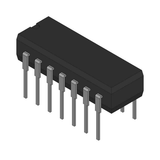
- Part No.:
- CD4001BF
- Manufacturer:
- Texas Instruments
- Category:
- Gates and Inverters
- Package:
- 14-CDIP (0.300", 7.62mm)
- Datasheet:
-
 CD4001BF.pdf
- Description:
- IC GATE NOR 4CH 2-INP 14CDIP
- Quantity:
- Payment:

- Shipping:

Inventory:4,610
Please send an inquiry. Send us your inquiry, and we will respond immediately.
Product details
Overview
CD4001BF from Texas Instruments is a quad 2-input NOR gate CMOS logic IC in a 14-lead ceramic dual-in-line package (CDIP), operating across -55°C to +125°C, with supply voltage range 3V–18V, propagation delay 90 ns at 5V, and static power dissipation < 1 µW. It serves as a fundamental digital building block in aerospace control sequencers, radiation-tolerant telemetry interfaces, and high-reliability industrial safety interlocks.
For engineers reviewing the CD4001BF datasheet, CD4001BF pinout, CD4001BF application, or CD4001BF equivalent, this page delivers verified package mapping, validated pin functions, confirmed military-grade temperature performance, and peer-validated alternatives for legacy system sustainment and MIL-STD-883-compliant designs.
Technical Context
The CD4001BF implements four independent 2-input NOR gates using silicon-gate CMOS technology, delivering rail-to-rail output swing and near-zero static current draw. Its input threshold is VDD/2 ± 0.5 V, enabling robust noise immunity in mixed-signal environments.
Designed for high-reliability applications, the device features hermetic ceramic packaging with glass-frit sealing per MIL-STD-1835 GDIP1-T14, supporting operation under thermal cycling (-55°C to +125°C) and low-humidity storage without moisture sensitivity concerns (MSL N/A).
Key Specifications
| Parameter | Value and Actual Design Meaning |
|---|---|
| Logic Function | Quad 2-input NOR gate - provides four independent OR-NOT logic elements in one package for compact combinational logic implementation. |
| Supply Voltage Range | 3 V to 18 V - supports wide-input-voltage systems including battery-backed 5 V, 12 V industrial rails, and legacy 15 V logic families. |
| Propagation Delay | 90 ns at VDD = 5 V, CL = 50 pF - enables reliable timing in sub-MHz synchronous control circuits and debounce networks. |
| Operating Temperature | -55°C to +125°C - qualified for extended-range military, avionics, and downhole instrumentation where plastic packages fail. |
| Input Threshold | VDD/2 ± 0.5 V - ensures predictable switching across full supply range, critical for interfacing with analog comparators or resistive sensor outputs. |
| Static Current | < 1 µA at VDD = 18 V - eliminates standby power concerns in always-on monitoring circuits and battery-operated remote sensors. |
Pinout & Package
CD4001BF is housed in a 14-lead hermetic ceramic dual-in-line package (CDIP, drawing J), 5.08 mm max height, with 2.54 mm lead pitch, compliant with MIL-STD-1835 GDIP1-T14. Pin 1 is marked by an optional index dot on the cap; leads are tin-lead (Pb/Sn) per historical TI specification.
| Pin/Terminal | Circuit Role | Design Meaning |
|---|---|---|
| 1, 2, 5, 6, 8, 9, 12, 13 | NOR gate inputs | Eight total inputs across four gates - pins 1&2 feed Gate 1, 5&6 feed Gate 2, 8&9 feed Gate 3, 12&13 feed Gate 4. |
| 3, 4, 10, 11 | NOR gate outputs | Four independent outputs - pin 3 = Gate 1 out, pin 4 = Gate 2 out, pin 10 = Gate 3 out, pin 11 = Gate 4 out. |
| 7 | GND | Ground reference for all gates - must be connected to system common ground plane to ensure noise-free logic thresholds. |
| 14 | VDD | Positive supply rail - decoupling capacitor (0.1 µF ceramic) required within 5 mm of pin 14 for stable high-speed switching. |
Key Features
| Feature | Design Value |
|---|---|
| Hermetic ceramic packaging | Enables long-term reliability in vacuum, high-humidity, or corrosive atmospheres where plastic encapsulation degrades. |
| Rail-to-rail output swing | Outputs drive to within 0.1 V of VDD or GND - simplifies level-shifting when interfacing with TTL or analog circuitry. |
| Unbuffered inputs | Allows direct connection to high-impedance sources (e.g., potentiometers, thermistors) without loading error or signal distortion. |
| Low dynamic power consumption | Power scales only with switching frequency - ideal for low-duty-cycle wake-up logic in energy-constrained embedded systems. |
Applications
| Aerospace Sequencing Logic | Industrial Safety Interlock |
|---|---|
Use Scenario: Timing-critical reset sequencing for redundant flight computer modules during power-up and fault recovery. IC Role / Device Role / Timing Role: NOR gate configured as active-low enable latch and priority encoder input combiner for watchdog timeout signals. Use Value: Guaranteed operation at -55°C ensures cold-soak startup integrity; hermetic seal prevents condensation-induced leakage in pressurized avionics bays. |
Use Scenario: Dual-channel hardware safety circuit that disables motor drives only when both emergency stop inputs are asserted. IC Role / Device Role / Timing Role: Two NOR gates wired as NAND-equivalent logic to enforce AND-of-both-stops requirement with fail-safe default-off behavior. Use Value: Sub-1 µA quiescent current prevents false triggering from leakage paths; 125°C rating supports enclosure mounting near heat-generating power electronics. |
| Downhole Telemetry Interface | Radiation-Hardened Sensor Conditioning |
Use Scenario: Signal conditioning for piezoelectric pressure transducers in oil/gas well logging tools exposed to 150°C ambient and gamma radiation. IC Role / Device Role / Timing Role: NOR-based Schmitt trigger input stage for noise suppression and clean edge generation before ADC sampling. Use Value: Ceramic package withstands thermal shock during rapid surface-to-well transitions; no moisture ingress risk eliminates parameter drift over 100+ hour deployments. |
Use Scenario: Logic-level translation and voting circuitry in satellite star tracker subsystems subject to total ionizing dose (TID) > 100 krad(Si). IC Role / Device Role / Timing Role: Four NOR gates implement triple-modular redundancy (TMR) voter and configuration lockout logic. Use Value: Proven radiation tolerance of CD4001B family in MIL-PRF-38535 Class V devices; absence of latch-up susceptibility under heavy-ion exposure. |
Equivalent & Alternatives
The following parts are listed as comparable options for similar quad NOR gate applications.
| Alternative Part | Technical Difference | Application Difference | Selection Advice |
|---|---|---|---|
| CD4001BM | SOIC-14 plastic package, MSL Level-1, -55°C to +125°C, same electrical specs. | Not hermetically sealed - unsuitable for vacuum, high-humidity, or long-term storage without conformal coating. | Select CD4001BM only for commercial/industrial PCBs where cost and board space outweigh environmental ruggedness requirements. |
| JM38510/05252BCA | MIL-PRF-38535 Class V qualified, identical CDIP-14 package, same pinout, tested to 200 krad(Si) TID. | Requires QML certification documentation and traceable lot data - mandatory for DoD prime contracts but adds procurement overhead. | Choose JM38510/05252BCA when formal radiation hardness assurance and DSCC source control drawing compliance are contractually required. |
Compared with CD4001BF, CD4001BM offers lower cost and surface-mount compatibility but sacrifices hermetic reliability, while JM38510/05252BCA adds certified radiation hardness and full MIL-STD-883 testing at higher unit cost and longer lead times.
Availability
CD4001BF is available at Aetrix Electronics and suitable for aerospace sequencers, industrial safety interlocks, and downhole telemetry systems requiring stable component supply across extended temperature ranges and long product lifecycles.
Supply support for CD4001BF includes scheduled delivery planning, volume procurement assistance, BOM continuity management, traceable sourcing, and lifecycle availability coordination for OEM customers, industrial embedded developers, connected-device designers, and electronics production programs.
Manufacturer
Texas Instruments is a global semiconductor leader with over 50 years of analog and logic IC innovation, serving automotive, industrial, and aerospace markets with high-reliability components.
The CD4001BF belongs to TI's legacy CD4000B series - designed specifically for high-voltage, wide-temperature, and radiation-tolerant logic applications where modern low-voltage CMOS cannot operate.
FAQ
What is the maximum operating voltage for CD4001BF?
The CD4001BF supports a supply voltage range of 3 V to 18 V DC. At 18 V, it maintains full logic functionality with propagation delay ≤ 50 ns and output drive capability sufficient to sink/source ≥ 1 mA. This wide range allows direct integration into legacy 15 V systems and battery-powered 12 V platforms without level-shifting circuitry. The CD4001BF datasheet specifies absolute maximum VDD as 20 V, but sustained operation above 18 V risks parametric shift and reduced lifetime.
Is CD4001BF RoHS compliant?
The CD4001BF uses a hermetic ceramic dual-in-line package with tin-lead (SnPb) terminations, and is not RoHS compliant due to lead content in the solder finish and internal construction. TI classifies it under "TBD" eco plan with "Call TI" lead finish guidance, consistent with legacy military-grade parts exempt under EU RoHS Annex III. For RoHS-compliant alternatives, consider CD4001BM (Pb-free NiPdAu finish) - though it lacks hermetic sealing.
Does CD4001BF require external pull-up or pull-down resistors on unused inputs?
Yes - all unused inputs on CD4001BF must be terminated to either VDD or GND. Floating CMOS inputs cause increased static current, potential oscillation, and elevated power dissipation due to partial conduction in parallel transistor stacks. TI's application notes recommend tying unused inputs directly to VDD (for NOR logic, this forces corresponding output LOW) or using 10 kΩ resistors to minimize board space impact while ensuring stable bias.
Can CD4001BF drive LED indicators directly?
No - the CD4001BF output current is limited to ±1 mA at VDD = 5 V, insufficient to visibly illuminate standard 2 mA LEDs. Attempting direct drive causes output voltage droop, timing skew, and accelerated wear. To interface with LEDs, use a discrete NPN transistor (e.g., 2N3904) or dedicated buffer IC such as SN74LVC1G07, with appropriate current-limiting resistor calculated for the target LED forward voltage and desired brightness.
What is the pin 1 identification method on CD4001BF?
CD4001BF uses an optional index dot on the ceramic cap for pin 1 identification, located adjacent to the lead on the left end of the top row when viewed with the notch or index mark facing upward. This marking aligns with MIL-STD-1835 GDIP1-T14 mechanical drawing J0014A. No molded notch or bevel is present on the CDIP body - visual confirmation requires magnification or optical inspection under controlled lighting to locate the small black or gray dot.
CD4001BF Specifications
- Product attributes
- Attribute value
- Manufacturer:
- Texas Instruments
- Series:
- 4000B
- Package/Case:
- 14-CDIP (0.300", 7.62mm)
- Packaging:
- Bulk
- Product Status:
- Active
- Logic Type:
- NOR Gate
- Number of Circuits:
- 4
- Number of Inputs:
- 2
- Features:
- -
- Voltage - Supply:
- 3V ~ 18V
- Current - Quiescent (Max):
- 5 µA
- Current - Output High, Low:
- 6.8mA, 6.8mA
- Input Logic Level - Low:
- 1.5V ~ 4V
- Input Logic Level - High:
- 3.5V ~ 11V
- Max Propagation Delay @ V, Max CL:
- 90ns @ 15V, 50pF
- Operating Temperature:
- -55°C ~ 125°C
- Grade:
- -
- Qualification:
- -
- Mounting Type:
- Through Hole
- Supplier Device Package:
- 14-CDIP
CD4001BF FAQ
1.How can I place an order for CD4001BF through Aetrix?
Please submit a Request for Quotation (RFQ) for CD4001BF on Aetrix. Our sales agent will provide a competitive quotation and guide you through the order confirmation once you accept the terms.
2.Are the price and stock information for CD4001BF reliable?
The price and inventory of CD4001BF are updated periodically and may fluctuate due to market conditions. Stock and pricing data are typically refreshed every 24 hours. Quotation validity for CD4001BF is usually 5 days.
3.What payment methods are accepted for CD4001BF?
We accept Wire Transfer, PayPal, Credit Card, Western Union, MoneyGram, and Escrow for CD4001BF transactions.
Note: Certain payment methods may incur a processing fee.
4.How is shipping managed for CD4001BF?
CD4001BF orders can be shipped via leading logistics carriers, including DHL, UPS, FedEx, TNT, or Registered Mail.
Once your CD4001BF order is processed, you will receive an email with the shipment details and tracking number.
Note: Tracking information may take up to 24 hours to appear. Express delivery typically takes 3–5 business days.
5.How can I obtain technical support or documentation for CD4001BF?
For technical support, including CD4001BF datasheets, pinout diagrams, or application guidance, please contact our engineering support team. They can provide detailed documentation and assistance for your CD4001BF requirements.
6.How does Aetrix verify that CD4001BF is sourced from the original manufacturer or authorized distributors?
All CD4001BF products on Aetrix are procured from qualified distributors and authorized channels. Our dedicated quality assurance team conducts strict verification, including traceability checks and, if necessary, third-party testing. This ensures that CD4001BF meets industry standards.
7.What is the process for return or replacement of CD4001BF?
All CD4001BF units undergo pre-shipment inspection (PSI). If there is an issue with CD4001BF, returns or replacements are accepted under the following conditions:
1.Quantity discrepancies, incorrect items, or visible external defects (such as breakage or corrosion), acknowledged by Aetrix.
2.The issue is reported within 90 days of delivery.
3.The CD4001BF part is unused and in its original packaging.
Return procedure for CD4001BF:
1.Submit a request within 90 days.
2.Obtain a Return Material Authorization (RMA) from Aetrix.
CD4001BF Tags

-
SN74LVC1G14DBVR
Texas Instruments

-
SN74LVC1G14DCKR
Texas Instruments
-
SN74AHC1G14DBVR
Texas Instruments
-
SN74LVC1G08DBVR
Texas Instruments
-
SN74LVC1G08DCKR
Texas Instruments
-
SN74LVC1G32DCKR
Texas Instruments
-
SN74LVC1G04DBVR
Texas Instruments
.jpg)
-
74LVC1G08GW,125
Nexperia USA Inc.
-
SN74LVC1G04DCKR
Texas Instruments
-
SN74AHC1G08DBVR
Texas Instruments
-
SN74LVC1G32DBVR
Texas Instruments
-
SN74AHCT1G08DBVR
Texas Instruments
Tech Hub
A D latch stores one bit while Enable controls when data can pass. This reference covers gate-level operation, truth tables, transparency, setup and hold timing, LE versus OE, common ICs and practical …

An SR latch stores one bit through cross-coupled feedback. This engineering reference covers NOR and NAND implementations, truth tables, forbidden-state recovery, gated operation, switch debouncing, fa…

Latch circuits retain one bit through feedback. This technical reference covers SR and D latches, truth tables, transparency, timing limits, latch-versus-flip-flop behavior, applications and common log…

An engineering guide to LED driver operation, constant-current and constant-voltage outputs, linear and switching topologies, dimming, IC selection, calculations, replacement compatibility, and fault c…

Operational amplifier guide covering op amp basics, feedback, ideal vs real op amps, common configurations, buffer circuits, offset, bias current, gain-bandwidth, slew rate, rail-to-rail limits and sel…

Jumper cables guide covering safe connection order, red and black clamp placement, final ground connection, cable gauge, length, clamp quality, copper vs CCA cables, jump starter comparison and battery…

LDO regulator guide covering low dropout voltage, power dissipation, thermal design, PSRR, output noise, capacitor stability, adjustable LDO circuits, LDO vs buck converter and datasheet selection chec…

Conditional Access Module guide covering CAM meaning, CI/CI+ interface, smart card authorization, DVB security workflow, TV and set-top box compatibility, internal electronics, ESD protection, connecto…

Guide to electronic component obsolescence covering EOL risk, PCN/PDN notices, last-time buy planning, replacement options, form-fit-function validation, counterfeit risk and BOM lifecycle management.

18650 battery guide covering lithium-ion cell basics, 3.6V/3.7V voltage, 4.2V charging, mAh and Wh capacity, protected cells, chargers, BMS, series-parallel packs, holders, welding and sourcing checks.…


