
 My Inquiry
 My Account


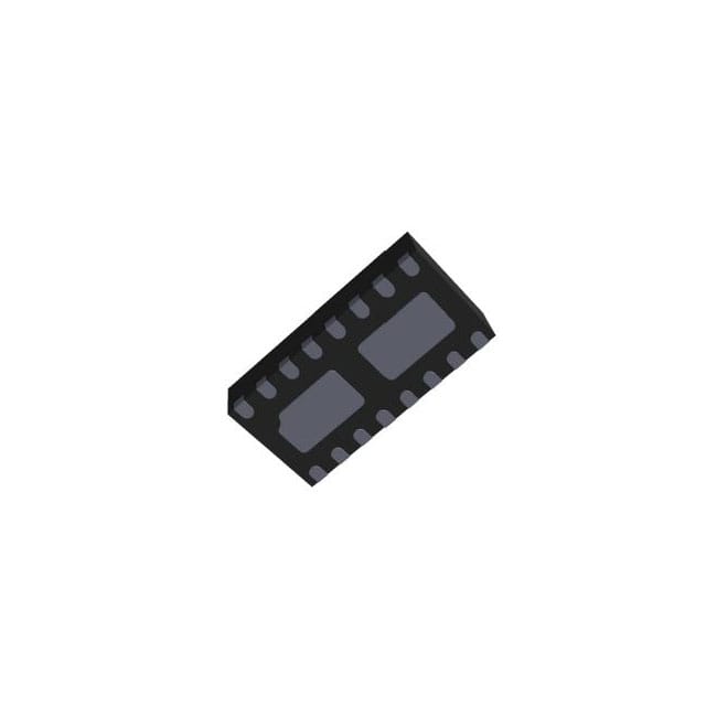
STMicroelectronics CLT03-2Q3
- Part No.:
- CLT03-2Q3
- Manufacturer:
- STMicroelectronics
- Category:
- Current Regulation/Management
- Package:
- 16-VFDFN Exposed Pad
- Datasheet:
-
 CLT03-2Q3.pdf
- Description:
- IC CURRENT LIMITING 16QFN
- Quantity:
- Payment:

- Shipping:

Inventory:3,717
Please send an inquiry. Send us your inquiry, and we will respond immediately.
Product details
Overview
CLT03-2Q3 from STMicroelectronics is a dual-channel, self-powered digital input current limiter for industrial PLC and remote I/O modules. It provides 4 mA typical input current limiting, ±2 kV IEC 61000-4-2 ESD protection, and operates across –30 °C to +125 °C ambient without external supply. It supports high-side/low-side and isolated/non-isolated configurations while meeting IEC 61131-2 Type 1 and Type 3 input characteristics.
For engineers reviewing the CLT03-2Q3 datasheet, CLT03-2Q3 pinout, CLT03-2Q3 application, or CLT03-2Q3 equivalent, key selection criteria include dual-channel current limiting accuracy (2.5–4 mA), fault-mode overvoltage response (30–40 V threshold), deglitch-filtered propagation delay (2–5 µs), and QFN-16L thermal resistance (41 °C/W).
Technical Context
The CLT03-2Q3 integrates two independent current-limiting channels with built-in deglitch filtering, test-pulse diagnostics, and dual-mode output drive (isolated LVTTL-compatible or non-isolated with internal pull-down). Each channel features programmable fault detection at ≥30 V input voltage and automatic current reduction to 1–2.5 mA in fault mode.
Its U-I characteristic conforms to IEC 61131-2 Type 1 (ULmax_H = 15 V) and Type 3 (ULmax_H = 11 V) limits, enabling direct interface with 24 V DC field sensors. The device draws zero quiescent power in OFF state and activates solely from input signal energy.
Key Specifications
| Parameter | Value and Actual Design Meaning |
|---|---|
| Input current limit (on state) | 2.5–4 mA - ensures compliance with IEC 61131-2 Type 1/3 current thresholds and minimizes field wiring power dissipation |
| Fault voltage threshold | 30–40 V - triggers safe current reduction during overvoltage transients common in factory automation environments |
| Propagation delay (tPLH/tPHL) | 2–5 µs - includes integrated deglitch filter, enabling robust operation in electrically noisy PLC backplanes |
| Operating temperature range | –30 °C to +125 °C - supports deployment in uncontrolled industrial enclosures and motor control cabinets |
| ESD immunity | ±2 kV contact discharge (IEC 61000-4-2 Level 1) - protects against handling and field-induced electrostatic events |
| Thermal resistance (Rth(j-a)) | 41 °C/W - enables reliable dual-channel operation at full ambient rating without forced cooling |
| Test pulse frequency range | 4.1–219 kHz - configurable via external 100–4700 pF capacitor for periodic functional self-test in safety-critical systems |
Pinout & Package
CLT03-2Q3 is housed in a thermally optimized QFN-16L package (4.0 × 2.0 mm, 0.5 mm pitch) with exposed thermal pad (TAB1/TAB2) for enhanced heat dissipation in high-density industrial PCB layouts.
| Pin/Terminal | Circuit Role | Design Meaning |
|---|---|---|
| INA1 / INA2 | Signal input (channel 1/2) | Primary logic input with 2.5–4 mA current limiting; compatible with 24 V DC field sensors |
| INATTL1 / INATTL2 | Signal input (non-isolated mode) | Enables direct LVTTL termination without optocoupler; used with PD1/PD2 pull-down resistors |
| INB1 / INB2 | Signal input (channel 1/2) | Secondary input path supporting reverse-plug compatibility and redundant sensing configurations |
| TP1 / TP2 | Test pulse control | Accepts external capacitor to enable periodic diagnostic low-pulse on OUTP1/OUTP2 for functional safety verification |
| VBUF1 / VBUF2 | Buffer capacitor node | Connects to local 100 nF capacitor to stabilize internal charge pump for self-powered operation |
| OUTN1 / OUTN2 | Logic ground (channel 1/2) | Isolated output return path; separates channel grounds to prevent crosstalk in multi-channel modules |
| OUTP1 / OUTP2 | Data output (channel 1/2) | CMOS-compatible output (0.7–3.6 V on-state); drives optocouplers or 3.3 V LVTTL receivers directly |
| PD1 / PD2 | Pull-down resistor node | Provides 2.85–4.25 kΩ internal pull-down for non-isolated mode; eliminates need for external resistors |
Key Features
| Feature | Design Value |
|---|---|
| Self-powered operation | No external supply required - powered entirely by input signal energy, eliminating auxiliary rails in remote I/O designs |
| Dual-channel isolation | 230 VAC channel-to-channel isolation - enables independent monitoring of multiple field devices on shared backplane |
| Integrated deglitch filter | 2–5 µs propagation with glitch suppression - prevents false triggering from EMI bursts in factory floor environments |
| Reverse-plug compatible inputs | INA/INB polarity tolerance - allows field wiring without concern for terminal orientation, reducing commissioning errors |
| Configurable test pulse | Capacitor-tuned 4.1–219 kHz diagnostic pulse - satisfies periodic self-test requirements per IEC 61508 SIL2 functional safety compliance |
Applications
| Programmable Logic Controller (PLC) Digital Input Module | Remote I/O Terminal Unit |
|---|---|
|
Use Scenario: 24 V DC discrete sensor signals (limit switches, proximity sensors) routed to centralized PLC rack via DIN-rail mounted input modules. IC Role / Device Role / Timing Role: Dual-channel current limiter and signal conditioner - replaces discrete resistor-diode-zener networks while providing fault-mode protection and EMC filtering. Use Value: Reduces board space by 60% vs. discrete solutions and eliminates external power rail, lowering system BOM cost and thermal load in densely packed modules. |
Use Scenario: Distributed I/O nodes installed near motors, conveyors, or hydraulic stations where ambient temperature exceeds 85 °C and EMI is severe. IC Role / Device Role / Timing Role: Self-powered digital input front-end - interfaces directly with 24 V field wiring while maintaining 2–5 µs deterministic response under 125 °C ambient. Use Value: Enables extended temperature operation without derating or heatsinking, and meets IEC 61000-4-2 Level 1 ESD immunity without external TVS diodes. |
| Industrial Safety Monitoring System | Machine Control Cabinet Input Interface |
|
Use Scenario: Safety-rated emergency stop and guard door monitoring circuits requiring periodic functional self-test per ISO 13849 PL e or IEC 61508 SIL2. IC Role / Device Role / Timing Role: Dual-channel diagnostic input conditioner - integrates capacitor-configurable test pulse generation and fault-mode current limiting for certified safety functions. Use Value: Eliminates external test circuitry and reduces validation effort by embedding diagnostic capability directly in the signal conditioning stage. |
Use Scenario: Modular machine tool control cabinets with mixed high-side and low-side field wiring, where input polarity varies across OEM equipment lines. IC Role / Device Role / Timing Role: Polarity-agnostic current limiter - accepts both high-side and low-side sourced inputs and supports reverse-plug field connectors without redesign. Use Value: Simplifies global manufacturing by enabling single PCB design across regional wiring standards (e.g., EU high-side vs. US low-side sourcing). |
Equivalent & Alternatives
The following parts are listed as comparable options for similar digital input current limiting applications.
| Alternative Part | Technical Difference | Application Difference | Selection Advice |
|---|---|---|---|
| CLT03-1SC3 | Single-channel SOT23-8L variant with higher Rth(j-a) (120 °C/W) and same electrical specs | Suitable for space-constrained single-input designs but lacks dual-channel integration and thermal performance | Select when board area is critical and only one input channel is needed per module |
| TI ISO1211 | Isolated 24 V digital input receiver with integrated galvanic isolation (no current limiting function) | Requires external current-limiting resistor and does not provide fault-mode current reduction or test pulse diagnostics | Select when reinforced isolation is mandatory and current limiting is handled externally |
Compared with CLT03-1SC3, the CLT03-2Q3 delivers dual-channel density and superior thermal performance (41 vs. 120 °C/W), while TI ISO1211 offers higher isolation rating but lacks integrated current limiting, fault response, and self-test - making CLT03-2Q3 optimal for compact, self-powered, safety-aware industrial input modules.
Availability
CLT03-2Q3 is available at Aetrix Electronics and suitable for programmable logic controller digital input modules, remote I/O terminal units, industrial safety monitoring systems, and machine control cabinet input interfaces requiring stable component supply and long-term industrial lifecycle support.
Supply support for CLT03-2Q3 includes scheduled delivery planning, volume procurement assistance, BOM continuity management, traceable sourcing, and lifecycle availability coordination for OEM customers, industrial embedded developers, connected-device designers, and electronics production programs.
Manufacturer
STMicroelectronics is a global semiconductor leader headquartered in Geneva, Switzerland, specializing in automotive, industrial, and power management ICs with strong focus on functional safety and industrial reliability.
The CLT03 series belongs to ST's industrial interface portfolio, designed specifically to replace discrete current-limiting networks in PLC and distributed I/O systems while delivering integrated EMC robustness, fault safety, and self-powered operation.
FAQ
Does CLT03-2Q3 require an external power supply?
No. CLT03-2Q3 is fully self-powered - it draws operating energy directly from the input signal and consumes zero current in the OFF state. Internal charge pump circuitry, stabilized by external VBUF capacitors, enables this functionality without auxiliary rails or regulators.
How does the test pulse feature work and what capacitor value is needed?
The test pulse feature uses an external capacitor between TP and OUTN pins to set pulse frequency: 100–4700 pF yields 4.1–219 kHz. At each period (256 × tTP), OUTP is forced low for tTP duration. This enables periodic functional verification without external test equipment, satisfying IEC 61508 diagnostic coverage requirements.
What is the difference between isolated and non-isolated modes?
In isolated mode, OUTP drives optocouplers using OUTN as dedicated ground; in non-isolated mode, PD pins provide internal 2.85–4.25 kΩ pull-downs to interface directly with 3.3 V LVTTL receivers. Configuration is determined by external circuit topology - no mode-select pin is required.
Can CLT03-2Q3 be used with both high-side and low-side field wiring?
Yes. CLT03-2Q3 supports both high-side and low-side sourcing due to its bidirectional input architecture and reverse-plug compatible INA/INB terminals. This eliminates wiring polarity concerns during installation and enables reuse across regional OEM standards without hardware changes.
CLT03-2Q3 Specifications
- Product attributes
- Attribute value
- Manufacturer:
- STMicroelectronics
- Series:
- -
- Package/Case:
- 16-VFDFN Exposed Pad
- Packaging:
- Tape & Reel (TR)
- Product Status:
- Active
- Function:
- Current Limiting
- Sensing Method:
- High/Low-Side
- Accuracy:
- -
- Voltage - Input:
- -60V ~ 60V
- Current - Output:
- 4mA
- Operating Temperature:
- -30°C ~ 125°C (TA)
- Grade:
- -
- Qualification:
- -
- Mounting Type:
- Surface Mount
- Supplier Device Package:
- 16-QFN (2x4)
CLT03-2Q3 FAQ
1.How can I place an order for CLT03-2Q3 through Aetrix?
Please submit a Request for Quotation (RFQ) for CLT03-2Q3 on Aetrix. Our sales agent will provide a competitive quotation and guide you through the order confirmation once you accept the terms.
2.Are the price and stock information for CLT03-2Q3 reliable?
The price and inventory of CLT03-2Q3 are updated periodically and may fluctuate due to market conditions. Stock and pricing data are typically refreshed every 24 hours. Quotation validity for CLT03-2Q3 is usually 5 days.
3.What payment methods are accepted for CLT03-2Q3?
We accept Wire Transfer, PayPal, Credit Card, Western Union, MoneyGram, and Escrow for CLT03-2Q3 transactions.
Note: Certain payment methods may incur a processing fee.
4.How is shipping managed for CLT03-2Q3?
CLT03-2Q3 orders can be shipped via leading logistics carriers, including DHL, UPS, FedEx, TNT, or Registered Mail.
Once your CLT03-2Q3 order is processed, you will receive an email with the shipment details and tracking number.
Note: Tracking information may take up to 24 hours to appear. Express delivery typically takes 3–5 business days.
5.How can I obtain technical support or documentation for CLT03-2Q3?
For technical support, including CLT03-2Q3 datasheets, pinout diagrams, or application guidance, please contact our engineering support team. They can provide detailed documentation and assistance for your CLT03-2Q3 requirements.
6.How does Aetrix verify that CLT03-2Q3 is sourced from the original manufacturer or authorized distributors?
All CLT03-2Q3 products on Aetrix are procured from qualified distributors and authorized channels. Our dedicated quality assurance team conducts strict verification, including traceability checks and, if necessary, third-party testing. This ensures that CLT03-2Q3 meets industry standards.
7.What is the process for return or replacement of CLT03-2Q3?
All CLT03-2Q3 units undergo pre-shipment inspection (PSI). If there is an issue with CLT03-2Q3, returns or replacements are accepted under the following conditions:
1.Quantity discrepancies, incorrect items, or visible external defects (such as breakage or corrosion), acknowledged by Aetrix.
2.The issue is reported within 90 days of delivery.
3.The CLT03-2Q3 part is unused and in its original packaging.
Return procedure for CLT03-2Q3:
1.Submit a request within 90 days.
2.Obtain a Return Material Authorization (RMA) from Aetrix.
CLT03-2Q3 Tags
.jpg)
-
PSSI2021SAY,115
Nexperia USA Inc.

-
BCR401RE6327HTSA1
Infineon Technologies

-
INA199B2DCKR
Texas Instruments
-
INA199A1DCKR
Texas Instruments
-
INA199B1DCKR
Texas Instruments
-
NSI45015WT1G
onsemi
-
NSI45020T1G
onsemi
-
NSI45030AT1G
onsemi
-
NSI45025AT1G
onsemi
-
NSI45020AT1G
onsemi
-
NSI50010YT1G
onsemi
-
LM334Z/NOPB
Texas Instruments
Tech Hub

A practical engineering and sourcing framework covering lifecycle verification, lifetime-buy calculations, replacement qualification, supplier checks and counterfeit-risk controls.

TTL and CMOS logic families differ in thresholds, loading, output drive, power and timing. This engineering guide compares 74HC and 74HCT, calculates noise margins and checks 3.3 V/5 V compatibility.

A practical engineering guide to 3.3V and 5V logic compatibility, input thresholds, resistor dividers, translator ICs, MOSFET level shifting, I2C pull-ups, timing limits and power-sequencing risks.

The 74HC595 uses push-pull logic outputs, while the TPIC6B595 uses 50 V open-drain DMOS sinks for higher-power loads. This guide compares timing, current limits, 3.3 V interfacing, load wiring, thermal…

The 74HC595 converts serial data into eight stable parallel outputs. This guide covers pin functions, shift and storage timing, OE and MR behavior, drive-current limits, cascading, voltage compatibilit…

A technical comparison of level-sensitive latches and edge-triggered flip-flops, covering timing windows, setup and hold limits, master–slave operation, time borrowing, race-through, HDL inference and…

A D latch stores one bit while Enable controls when data can pass. This reference covers gate-level operation, truth tables, transparency, setup and hold timing, LE versus OE, common ICs and practical …

An SR latch stores one bit through cross-coupled feedback. This engineering reference covers NOR and NAND implementations, truth tables, forbidden-state recovery, gated operation, switch debouncing, fa…

Latch circuits retain one bit through feedback. This technical reference covers SR and D latches, truth tables, transparency, timing limits, latch-versus-flip-flop behavior, applications and common log…

An engineering guide to LED driver operation, constant-current and constant-voltage outputs, linear and switching topologies, dimming, IC selection, calculations, replacement compatibility, and fault c…


