
 My Inquiry
 My Account


Renesas CP82C54-12
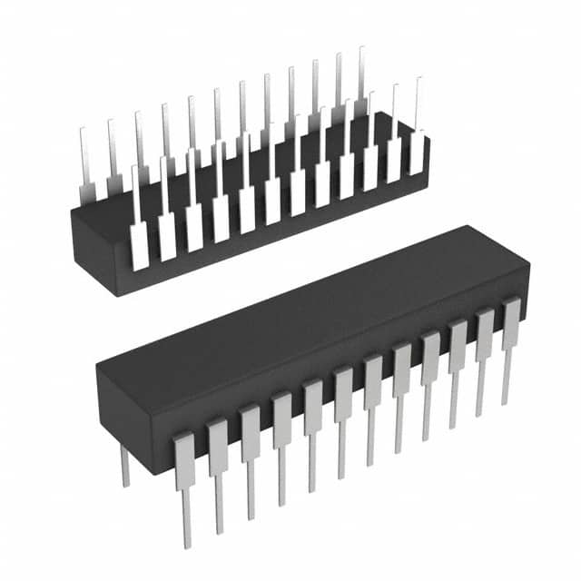
- Part No.:
- CP82C54-12
- Manufacturer:
- Renesas
- Category:
- Programmable Timers and Oscillators
- Package:
- 24-DIP (0.600", 15.24mm)
- Datasheet:
-
 CP82C54-12.pdf
- Description:
- IC OSC PROG TIMER 12MHZ 24DIP
- Quantity:
- Payment:

- Shipping:

Inventory:1,415
Please send an inquiry. Send us your inquiry, and we will respond immediately.
Product details
Overview
CP82C54-12 from Intersil is a CMOS programmable interval timer IC with three independent 16-bit counters, supporting up to 12MHz clock input frequency, binary or BCD counting, six programmable modes, and TTL-compatible 5V operation - used for real-time clock generation, event counting, and programmable rate control in legacy x86 embedded systems.
For engineers reviewing the CP82C54-12 datasheet, CP82C54-12 pinout, CP82C54-12 application, or CP82C54-12 equivalent, key selection considerations include its 12MHz maximum clock rating, PDIP-24 package compatibility with 80C86/80C88 systems, status read-back command support, and static CMOS low-power operation (10µA standby).
Technical Context
The CP82C54-12 implements three fully independent synchronous down-counters, each configurable via an 8-bit control word specifying mode (0–5), count format (binary/BCD), and read/write sequence. Its internal architecture includes separate count registers (CR), output latches (OL), and counting elements (CE) enabling non-disruptive "on-the-fly" count reads via Counter Latch or Read-Back commands.
It interfaces directly to 8-bit data buses using RD/WR/CS/A0/A1 control logic, supports gate-synchronized counting, and delivers deterministic timing outputs (OUT0–OUT2) with defined setup/hold and delay specifications - e.g., 85ns max data delay from RD at 12MHz, 30ns min CLK high pulse width, and 50ns gate setup time relative to CLK.
Key Specifications
| Parameter | Value and Actual Design Meaning |
|---|---|
| Max Clock Input | 12MHz - enables precise microsecond-scale timing intervals in high-speed 80C86/80C286 systems. |
| Counter Width | 16-bit - provides 65,536-step resolution per counter for extended timing ranges. |
| Supply Voltage | +4.5V to +5.5V - ensures robust operation across industrial-grade 5V rail tolerances. |
| Standby Current | 10µA - allows low-power sleep states in battery-backed or energy-sensitive designs. |
| Operating Temp | 0°C to +70°C - certified for commercial-temperature industrial control and PC-compatible hardware. |
| I/O Compatibility | Fully TTL-compatible - eliminates level-shifting requirements when interfacing with standard 5V logic families. |
| Count Modes | Six programmable modes - supports interrupt-on-terminal-count, programmable one-shot, square-wave generation, and rate generator functions. |
Pinout & Package
CP82C54-12 is supplied in a 24-lead plastic dual in-line package (PDIP), pin-compatible with industry-standard 8254 timers and suitable for through-hole mounting. Thermal resistance θJA is 55°C/W (plastic package).
| Pin/Terminal | Circuit Role | Design Meaning |
|---|---|---|
| D0–D7 | Data bus I/O | Bi-directional 8-bit interface to CPU data bus; three-state controlled by RD/WR/CS. |
| CLK0–CLK2 | Counter clock inputs | Independent timing sources per counter; accept up to 12MHz TTL-level signals. |
| GATE0–GATE2 | Counter enable inputs | Asynchronous gate control: high enables counting, low freezes current count value. |
| OUT0–OUT2 | Counter output signals | Active-high or active-low waveform outputs per programmed mode; drive TTL loads directly. |
| A0, A1 | Address select | Selects Counter 0/1/2 or Control Word Register (A1,A0 = 11) for read/write operations. |
| CS, RD, WR | Chip control | Standard 8086-style bus interface: CS enables device, RD initiates read, WR initiates write. |
| VCC, GND | Power supply | +5V supply with recommended 0.1µF decoupling capacitor between VCC and GND. |
Key Features
| Feature | Design Value |
|---|---|
| Status Read-Back Command | Enables software monitoring of OUT pin state, null-count flag, and active mode without halting operation. |
| Counter Latch Function | Latches current count value on demand, allowing safe "on-the-fly" reads while counting continues uninterrupted. |
| Binary or BCD Counting | Supports both 16-bit binary (0–65535) and decade-coded BCD (0000–9999) for legacy system compatibility. |
| Static CMOS Design | Eliminates dynamic power draw during idle cycles, reducing total system power in always-on applications. |
| Industry-Standard Pinout | Direct drop-in replacement for NMOS 8254 in existing PCB layouts, preserving board design integrity. |
Applications
| Real-Time Clock (RTC) | Event Counter |
|---|---|
Use Scenario: Generating accurate 1Hz timebase for system clocks in industrial HMIs and legacy PCs. IC Role / Device Role / Timing Role: Counter 0 configured in Mode 3 (square wave) with 12MHz input divided by 12,000,000 to produce precise 1Hz output. Use Value: Eliminates need for external crystal oscillators or software timing loops, improving accuracy and reducing CPU overhead. | Use Scenario: Monitoring mechanical encoder pulses in motor control feedback circuits. IC Role / Device Role / Timing Role: Counter 1 operating in Mode 0 (interrupt on terminal count) to tally rising-edge pulses from quadrature encoder outputs. Use Value: Provides hardware-accelerated, cycle-accurate position tracking independent of CPU scheduling latency. |
| Programmable One-Shot | Waveform Generator |
Use Scenario: Generating fixed-duration enable pulses for solenoid drivers in automated test equipment. IC Role / Device Role / Timing Role: Counter 2 in Mode 1 (hardware retriggerable one-shot), triggered by external GATE signal to produce calibrated output pulse width. Use Value: Delivers jitter-free, repeatable timing windows without software intervention or timer ISR overhead. | Use Scenario: Producing variable-frequency square waves for audio tone generation in embedded instrumentation. IC Role / Device Role / Timing Role: Counter 0 in Mode 3 (square wave), dynamically reloaded via software to adjust output frequency across 12MHz/65536 ≈ 183Hz to 12MHz range. Use Value: Enables real-time frequency modulation using only CPU register writes - no external DAC or PLL required. |
Equivalent & Alternatives
The following parts are listed as comparable options for similar programmable timer applications.
| Alternative Part | Technical Difference | Application Difference | Selection Advice |
|---|---|---|---|
| CP82C54-12Z | Pb-free version of CP82C54-12; identical electrical specs and pinout; RoHS-compliant matte tin termination. | Required for new designs targeting RoHS compliance; not suitable for reflow soldering (wave-only). | Select CP82C54-12Z for new production where lead-free assembly is mandated. |
| CS82C54-12 | Same core functionality but in 28-pin PLCC package; different pin mapping and thermal characteristics (θJA = 60°C/W). | Used where surface-mount layout or higher I/O density is needed; requires PCB redesign. | Choose CS82C54-12 only when upgrading from PDIP to PLCC footprint is acceptable. |
Compared with CP82C54-12, CP82C54-12Z offers identical timing performance with RoHS compliance, while CS82C54-12 trades through-hole convenience for surface-mount flexibility - neither is pin-compatible without layout changes, and both retain full functional equivalence for legacy 8254-based firmware.
Availability
CP82C54-12 is available at Aetrix Electronics and suitable for industrial control panels, legacy PC motherboard repairs, and embedded instrumentation requiring stable component supply and long-term obsolescence management.
Supply support for CP82C54-12 includes scheduled delivery planning, volume procurement assistance, BOM continuity management, traceable sourcing, and lifecycle availability coordination for OEM customers, industrial embedded developers, connected-device designers, and electronics production programs.
Manufacturer
Intersil Corporation was a U.S.-based semiconductor company specializing in high-performance analog and mixed-signal ICs, later acquired by Renesas Electronics in 2017.
The 82C54 family was designed as a CMOS-enhanced, drop-in upgrade to the NMOS 8254 for power-sensitive 8086/80286-era systems - emphasizing low standby current, TTL compatibility, and backward software compatibility.
FAQ
What is the maximum clock frequency supported by the CP82C54-12?
The CP82C54-12 supports a maximum clock input frequency of 12MHz across all three counters, verified in AC electrical specifications (TCLK min = 80ns). This rating applies specifically to the CP82C54-12 variant - lower-speed versions (CP82C54, CP82C54-10) are rated for 8MHz and 10MHz respectively. The 12MHz capability enables sub-microsecond timing resolution in legacy x86 systems.
Does the CP82C54-12 support BCD counting mode?
Yes, the CP82C54-12 supports Binary-Coded Decimal (BCD) counting via the BCD bit (D0) in the control word. When set to '1', the counter operates in 4-decade BCD mode (0000–9999); when '0', it uses 16-bit binary (0–65535). This feature ensures compatibility with legacy systems requiring decimal-aligned timing, such as older industrial controllers and measurement instruments that rely on BCD display drivers.
Can the CP82C54-12 be used as a direct replacement for the NMOS 8254?
Yes, the CP82C54-12 is explicitly designed as a pin-compatible, functionally enhanced replacement for the NMOS 8254. It retains identical pinout, control protocol, and register mapping while adding static CMOS benefits: lower power (10µA standby), higher speed (12MHz vs. 8MHz), and improved noise immunity. Firmware written for the 8254 runs unchanged on the CP82C54-12, making it ideal for drop-in upgrades in existing designs.
What is the purpose of the Read-Back command in the CP82C54-12?
The Read-Back command in the CP82C54-12 allows software to simultaneously latch and read counter status (OUT pin state, null-count flag, and programmed mode) and/or current count values without stopping timing operations. Issued via the control word register with D5/D4 = 0, it enables real-time diagnostics and synchronized monitoring - critical for safety-critical applications like motor control where output state verification must occur mid-operation.
Is the CP82C54-12 available in RoHS-compliant packaging?
Yes, the RoHS-compliant version is designated CP82C54-12Z - a Pb-free variant with 100% matte tin termination, qualified for wave soldering (not reflow). It matches the CP82C54-12 electrically and functionally, including 12MHz operation, 0°C to +70°C temperature range, and PDIP-24 package. Documentation confirms its compliance with IPC/JEDEC J-STD-020 reflow classifications despite being intended for wave-only processing.
CP82C54-12 Specifications
- Product attributes
- Attribute value
- Manufacturer:
- Renesas
- Series:
- -
- Package/Case:
- 24-DIP (0.600", 15.24mm)
- Packaging:
- Tube
- Product Status:
- Obsolete
- Type:
- Programmable Timer
- Count:
- -
- Frequency:
- 12MHz
- Voltage - Supply:
- 4.5V ~ 5.5V
- Current - Supply:
- 10 mA
- Operating Temperature:
- 0°C ~ 70°C
- Supplier Device Package:
- 24-PDIP
- Mounting Type:
- Through Hole
- Grade:
- -
- Qualification:
- -
CP82C54-12 FAQ
1.How can I place an order for CP82C54-12 through Aetrix?
Please submit a Request for Quotation (RFQ) for CP82C54-12 on Aetrix. Our sales agent will provide a competitive quotation and guide you through the order confirmation once you accept the terms.
2.Are the price and stock information for CP82C54-12 reliable?
The price and inventory of CP82C54-12 are updated periodically and may fluctuate due to market conditions. Stock and pricing data are typically refreshed every 24 hours. Quotation validity for CP82C54-12 is usually 5 days.
3.What payment methods are accepted for CP82C54-12?
We accept Wire Transfer, PayPal, Credit Card, Western Union, MoneyGram, and Escrow for CP82C54-12 transactions.
Note: Certain payment methods may incur a processing fee.
4.How is shipping managed for CP82C54-12?
CP82C54-12 orders can be shipped via leading logistics carriers, including DHL, UPS, FedEx, TNT, or Registered Mail.
Once your CP82C54-12 order is processed, you will receive an email with the shipment details and tracking number.
Note: Tracking information may take up to 24 hours to appear. Express delivery typically takes 3–5 business days.
5.How can I obtain technical support or documentation for CP82C54-12?
For technical support, including CP82C54-12 datasheets, pinout diagrams, or application guidance, please contact our engineering support team. They can provide detailed documentation and assistance for your CP82C54-12 requirements.
6.How does Aetrix verify that CP82C54-12 is sourced from the original manufacturer or authorized distributors?
All CP82C54-12 products on Aetrix are procured from qualified distributors and authorized channels. Our dedicated quality assurance team conducts strict verification, including traceability checks and, if necessary, third-party testing. This ensures that CP82C54-12 meets industry standards.
7.What is the process for return or replacement of CP82C54-12?
All CP82C54-12 units undergo pre-shipment inspection (PSI). If there is an issue with CP82C54-12, returns or replacements are accepted under the following conditions:
1.Quantity discrepancies, incorrect items, or visible external defects (such as breakage or corrosion), acknowledged by Aetrix.
2.The issue is reported within 90 days of delivery.
3.The CP82C54-12 part is unused and in its original packaging.
Return procedure for CP82C54-12:
1.Submit a request within 90 days.
2.Obtain a Return Material Authorization (RMA) from Aetrix.
CP82C54-12 Tags

-
NE555DR
Texas Instruments
-
SA555DR
Texas Instruments
-
NA555DR
Texas Instruments
-
SE555DR
Texas Instruments

-
NE555P
Texas Instruments

-
CD4541BM96
Texas Instruments

-
CD4541BE
Texas Instruments
-
TLC555QDR
Texas Instruments
-
TLC555IDR
Texas Instruments
-
TLC555QDRQ1
Texas Instruments

-
TPL5010DDCR
Texas Instruments
-
TLC555CP
Texas Instruments
Tech Hub

TTL and CMOS logic families differ in thresholds, loading, output drive, power and timing. This engineering guide compares 74HC and 74HCT, calculates noise margins and checks 3.3 V/5 V compatibility.

A practical engineering guide to 3.3V and 5V logic compatibility, input thresholds, resistor dividers, translator ICs, MOSFET level shifting, I2C pull-ups, timing limits and power-sequencing risks.

The 74HC595 uses push-pull logic outputs, while the TPIC6B595 uses 50 V open-drain DMOS sinks for higher-power loads. This guide compares timing, current limits, 3.3 V interfacing, load wiring, thermal…

The 74HC595 converts serial data into eight stable parallel outputs. This guide covers pin functions, shift and storage timing, OE and MR behavior, drive-current limits, cascading, voltage compatibilit…

A technical comparison of level-sensitive latches and edge-triggered flip-flops, covering timing windows, setup and hold limits, master–slave operation, time borrowing, race-through, HDL inference and…

A D latch stores one bit while Enable controls when data can pass. This reference covers gate-level operation, truth tables, transparency, setup and hold timing, LE versus OE, common ICs and practical …

An SR latch stores one bit through cross-coupled feedback. This engineering reference covers NOR and NAND implementations, truth tables, forbidden-state recovery, gated operation, switch debouncing, fa…

Latch circuits retain one bit through feedback. This technical reference covers SR and D latches, truth tables, transparency, timing limits, latch-versus-flip-flop behavior, applications and common log…

An engineering guide to LED driver operation, constant-current and constant-voltage outputs, linear and switching topologies, dimming, IC selection, calculations, replacement compatibility, and fault c…

Operational amplifier guide covering op amp basics, feedback, ideal vs real op amps, common configurations, buffer circuits, offset, bias current, gain-bandwidth, slew rate, rail-to-rail limits and sel…


