
 My Inquiry
 My Account


onsemi CS5231-3GDP5
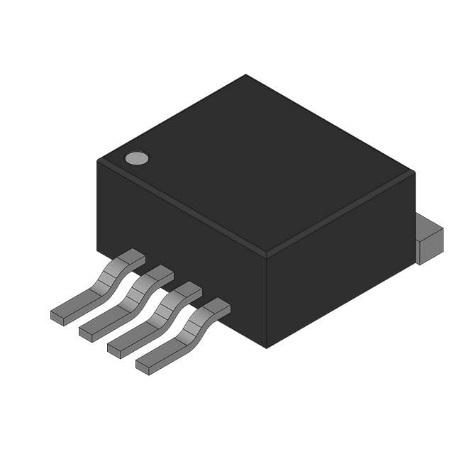
- Part No.:
- CS5231-3GDP5
- Manufacturer:
- onsemi
- Package:
- TO-263-6, D2PAK (5 Leads + Tab), TO-263BA
- Datasheet:
-
 CS5231-3GDP5.pdf
- Description:
- IC REG LINEAR FIXED LDO REG
- Quantity:
- Payment:

- Shipping:

Inventory:3,050
Please send an inquiry. Send us your inquiry, and we will respond immediately.
Product details
Overview
CS5231-3GDP5 from onsemi is a 500 mA, 3.3 V fixed-output linear regulator with integrated auxiliary supply control for dual-input power management. It delivers uninterrupted 3.3 V output by switching between a main 5.0 V input and an auxiliary 3.3 V source using an external PFET, meeting Intel's "Instantly Available" power requirements per ACPI standards. Designed for PCI NICs and desktop systems, it features ±2.0% output accuracy, low dropout, and reverse current protection.
For engineers reviewing the CS5231-3GDP5 datasheet, pinout, applications, or equivalent options, key selection considerations include its VIN threshold hysteresis (75–125 mV), AuxDrv drive capability (10 mA sink / 50 mA source), thermal shutdown at 180°C with 25°C hysteresis, and compatibility with ≥10 µF/≤1.0 Ω ESR output capacitors in D2PAK-5 packaging.
Technical Context
The CS5231-3GDP5 integrates a composite NPN-PNP pass transistor for low-dropout regulation and an internal 10 kΩ pull-up resistor plus saturating NPN switch on the AuxDrv pin to manage external PFET gate control. Its dual-threshold UVLO (4.25–4.65 V turn-on/off) with hysteresis ensures glitch-free transitions between input sources.
Operation relies on precise interaction between VIN monitoring, error amplifier feedback (internally fixed at 3.3 V), and AuxDrv timing: a 15 µs delay between regulator enable and AuxDrv pull-up prevents chatter during supply switchover, while reverse current protection limits VOUT-to-VIN leakage to ≤1.0 mA when VIN = 0 V.
Key Specifications
| Parameter | Value and Actual Design Meaning |
|---|---|
| Output Voltage | 3.3 V ±2.0% - Ensures stable ASIC core voltage under load (10–500 mA) without external feedback adjustment. |
| Max Output Current | 500 mA - Supports mid-power PCI interface loads; current limit trips at 0.55–1.2 A to protect against shorts. |
| VIN Threshold Hysteresis | 75–125 mV - Prevents oscillatory switching during slow-ramp or noisy 5.0 V supply transitions. |
| AuxDrv Sink/Source | 100 µA sink @ 0.4 V max / 50 mA source - Directly drives standard PFET gates without level-shifting circuitry. |
| Reverse Output Current | ≤1.0 mA @ VOUT = 3.3 V, VIN = 0 V - Minimizes standby power loss and protects auxiliary rail integrity. |
| Thermal Shutdown | 180°C trip with 25°C hysteresis - Self-recovering protection avoids latch-up during transient overloads. |
| Ground Current | 3.0 mA @ 500 mA load - Low quiescent draw supports energy-efficient sleep-state operation. |
Pinout & Package
D2PAK-5 (TO-263) package with exposed tab tied to GND for thermal conduction and EMI reduction. Five leads in single-row surface-mount configuration.
| Pin/Terminal | Circuit Role | Design Meaning |
|---|---|---|
| 1 | No Connect | Unbonded die pad; must remain floating or grounded per layout guidelines to avoid parasitic coupling. |
| 2 | VIN | Main 5.0 V input (4.75–6.0 V operating range); absolute max 14 V - connects to primary system rail. |
| 3 & Tab | GND | Power ground reference and thermal path; tab soldering required for full thermal performance in D2PAK-5. |
| 4 | VOUT | Regulated 3.3 V output; requires ≥10 µF/≤1.0 Ω ESR capacitor for stability and transient response. |
| 5 | AuxDrv | Active-low PFET gate driver; pulls low (<0.4 V) when VIN < ~4.4 V to enable auxiliary supply path. |
Key Features
| Feature | Design Value |
|---|---|
| Glitch-free dual-supply transition | 15 µs controlled delay between regulator enable and AuxDrv pull-up eliminates output voltage dip or overshoot during switchover. |
| ACPI-compliant power sequencing | Fully satisfies Intel's "Instantly Available" specification for sleep/wake transitions in PCI-based systems. |
| Low reverse leakage | 450 µA typical reverse current prevents auxiliary rail discharge and maintains system state during main supply brownout. |
| Internally fused SOIC-8 option | Not applicable to CS5231-3GDP5 - this D2PAK-5 variant lacks internal fusing; fusing is exclusive to SOIC-8 DF suffix parts. |
| Thermal fault recovery | 25°C hysteresis enables autonomous restart after junction cools below 155°C, eliminating need for external reset logic. |
Applications
| PCI Network Interface Card (NIC) | Desktop Computer Power Management |
|---|---|
Use Scenario: System enters ACPI S3 sleep state; 5.0 V rail drops below 4.4 V while 3.3 V auxiliary remains active. IC Role / Device Role / Timing Role: CS5231-3GDP5 monitors VIN, asserts AuxDrv to turn on external PFET, and maintains uninterrupted 3.3 V to ASIC within <1 µs of threshold crossing. Use Value: Eliminates reset or data loss in network controllers during rapid sleep/wake cycles per Intel platform requirements. | Use Scenario: Motherboard VRM supplies fluctuate during CPU load transients; auxiliary 3.3 V rail provides backup during brief 5.0 V dips. IC Role / Device Role / Timing Role: CS5231-3GDP5 acts as seamless failover regulator, sourcing load current from VAUX via PFET when VIN sags outside 4.25–4.65 V window. Use Value: Guarantees continuous operation of USB controllers, SMBus interfaces, and other 3.3 V peripherals without software intervention. |
| PCMCIA/PCI Hot-Swap Card | Industrial Embedded Controller |
Use Scenario: Card insertion causes inrush into uncharged output capacitance; main 5.0 V rises slowly while VAUX is pre-biased. IC Role / Device Role / Timing Role: CS5231-3GDP5 uses PFET body diode conduction initially, then transitions to regulated mode once VIN exceeds 4.5 V threshold. Use Value: Prevents bus lockup or enumeration failure by sustaining VDD during hot-plug ramp-up with no external sequencing logic. | Use Scenario: Factory automation controller requires fail-safe 3.3 V for FPGA configuration memory during AC line interruption. IC Role / Device Role / Timing Role: CS5231-3GDP5 switches to battery-backed 3.3 V auxiliary supply within 1 µs of main rail collapse, maintaining SRAM retention and watchdog supervision. Use Value: Enables deterministic recovery and zero-downtime operation in safety-critical PLC modules. |
Equivalent & Alternatives
The following parts are listed as comparable options for similar dual-input linear regulator applications.
| Alternative Part | Technical Difference | Application Difference | Selection Advice |
|---|---|---|---|
| TPS7A6033QDGKRQ1 | Automotive-grade 3.3 V LDO (500 mA), no auxiliary control; requires external circuitry for dual-supply management. | Lacks integrated AuxDrv logic - cannot perform automatic glitch-free switchover without added comparators, MOSFET drivers, and timing components. | Select only if functional safety certification (AEC-Q100) is mandatory and dual-supply autonomy is handled elsewhere in design. |
| NCP1117ST33T3G | 3.3 V, 1 A LDO with thermal shutdown and current limit; no VIN monitoring or auxiliary drive capability. | Single-input only - cannot interface with auxiliary 3.3 V rail; suitable only for fixed-rail applications without redundancy requirements. | Choose when cost sensitivity outweighs dual-source functionality and board space allows discrete switchover implementation. |
Compared with TPS7A6033QDGKRQ1 and NCP1117ST33T3G, the CS5231-3GDP5 uniquely integrates both regulation and intelligent source selection in one D2PAK-5 package, reducing BOM count by ≥4 components and eliminating timing-critical layout constraints associated with discrete solutions.
Availability
CS5231-3GDP5 is available at Aetrix Electronics and suitable for PCI NICs, desktop motherboard power domains, PCMCIA hot-swap cards, and industrial embedded controllers requiring stable component supply across extended product lifecycles.
Supply support for CS5231-3GDP5 includes scheduled delivery planning, volume procurement assistance, BOM continuity management, traceable sourcing, and lifecycle availability coordination for OEM customers, industrial embedded developers, connected-device designers, and electronics production programs.
Manufacturer
onsemi (formerly ON Semiconductor) is a global semiconductor supplier focused on energy-efficient innovation for automotive, industrial, cloud, and IoT applications.
The CS5231-3GDP5 belongs to onsemi's power management IC portfolio designed specifically for ACPI-compliant, multi-rail computing platforms where seamless power source handoff is critical to system responsiveness and reliability.
FAQ
What is the maximum allowable input voltage for CS5231-3GDP5?
The absolute maximum VIN rating for CS5231-3GDP5 is 14 V, but its specified operating range is strictly 4.75 V to 6.0 V. Exceeding 6.0 V increases power dissipation and thermal stress beyond guaranteed performance limits, potentially triggering thermal shutdown or degrading long-term reliability. The device is optimized for 5.0 V PCI bus environments, not wide-input industrial rails.
Does CS5231-3GDP5 support remote output voltage sensing?
No, CS5231-3GDP5 does not support remote sensing. Its feedback network is internal and fixed at 3.3 V, so output voltage regulation accuracy depends entirely on PCB trace resistance between the VOUT pin and load. To minimize error, place the CS5231-3GDP5 close to the load and use wide copper traces for both VOUT and GND connections - especially critical for 500 mA loads where even 50 mΩ trace resistance causes 25 mV drop.
How does the AuxDrv pin behave during power-up of CS5231-3GDP5?
During power-up, AuxDrv remains low until VIN reaches ~4.5 V (typical upper threshold), enabling the external PFET to conduct from VAUX. Once VIN crosses the threshold, AuxDrv transitions high after a 15 µs delay, turning off the PFET and enabling the internal linear regulator. This sequence ensures the load is never unpowered - VAUX supplies current until regulation stabilizes, preventing glitches during startup.
Can CS5231-3GDP5 be used without an external PFET?
No - the CS5231-3GDP5 requires an external p-channel FET to implement auxiliary supply control. Without it, the device functions only as a basic 3.3 V LDO with no switchover capability. The AuxDrv pin is not intended to drive loads directly; its 50 mA source capability is sized solely for PFET gate charging. Omitting the PFET disables the core dual-input feature and voids ACPI compliance claims.
What output capacitor specifications are mandatory for stable operation of CS5231-3GDP5?
CS5231-3GDP5 requires an output capacitor of ≥10 µF with ESR ≤1.0 Ω for guaranteed stability across temperature and load. Tantalum or polymer capacitors are preferred over aluminum electrolytics due to lower ESR and better high-frequency response. Using undersized or high-ESR capacitors risks oscillation, poor transient response, and failure to meet ±2.0% output tolerance under dynamic load conditions.
CS5231-3GDP5 Specifications
- Product attributes
- Attribute value
- Manufacturer:
- onsemi
- Series:
- -
- Package/Case:
- TO-263-6, D2PAK (5 Leads + Tab), TO-263BA
- Packaging:
- Bulk
- Product Status:
- Active
- Output Configuration:
- Positive
- Output Type:
- Fixed
- Number of Regulators:
- 1
- Voltage - Input (Max):
- 14V
- Voltage - Output (Min/Fixed):
- 3.3V
- Voltage - Output (Max):
- -
- Voltage Dropout (Max):
- -
- Current - Output:
- 500mA
- Current - Quiescent (Iq):
- 3 mA
- Current - Supply (Max):
- 6 mA
- PSRR:
- -
- Control Features:
- -
- Protection Features:
- Over Current, Over Temperature
- Operating Temperature:
- 0°C ~ 70°C
- Grade:
- -
- Qualification:
- -
- Mounting Type:
- Surface Mount
- Supplier Device Package:
- D2PAK-5
CS5231-3GDP5 FAQ
1.How can I place an order for CS5231-3GDP5 through Aetrix?
Please submit a Request for Quotation (RFQ) for CS5231-3GDP5 on Aetrix. Our sales agent will provide a competitive quotation and guide you through the order confirmation once you accept the terms.
2.Are the price and stock information for CS5231-3GDP5 reliable?
The price and inventory of CS5231-3GDP5 are updated periodically and may fluctuate due to market conditions. Stock and pricing data are typically refreshed every 24 hours. Quotation validity for CS5231-3GDP5 is usually 5 days.
3.What payment methods are accepted for CS5231-3GDP5?
We accept Wire Transfer, PayPal, Credit Card, Western Union, MoneyGram, and Escrow for CS5231-3GDP5 transactions.
Note: Certain payment methods may incur a processing fee.
4.How is shipping managed for CS5231-3GDP5?
CS5231-3GDP5 orders can be shipped via leading logistics carriers, including DHL, UPS, FedEx, TNT, or Registered Mail.
Once your CS5231-3GDP5 order is processed, you will receive an email with the shipment details and tracking number.
Note: Tracking information may take up to 24 hours to appear. Express delivery typically takes 3–5 business days.
5.How can I obtain technical support or documentation for CS5231-3GDP5?
For technical support, including CS5231-3GDP5 datasheets, pinout diagrams, or application guidance, please contact our engineering support team. They can provide detailed documentation and assistance for your CS5231-3GDP5 requirements.
6.How does Aetrix verify that CS5231-3GDP5 is sourced from the original manufacturer or authorized distributors?
All CS5231-3GDP5 products on Aetrix are procured from qualified distributors and authorized channels. Our dedicated quality assurance team conducts strict verification, including traceability checks and, if necessary, third-party testing. This ensures that CS5231-3GDP5 meets industry standards.
7.What is the process for return or replacement of CS5231-3GDP5?
All CS5231-3GDP5 units undergo pre-shipment inspection (PSI). If there is an issue with CS5231-3GDP5, returns or replacements are accepted under the following conditions:
1.Quantity discrepancies, incorrect items, or visible external defects (such as breakage or corrosion), acknowledged by Aetrix.
2.The issue is reported within 90 days of delivery.
3.The CS5231-3GDP5 part is unused and in its original packaging.
Return procedure for CS5231-3GDP5:
1.Submit a request within 90 days.
2.Obtain a Return Material Authorization (RMA) from Aetrix.
CS5231-3GDP5 Tags

-
MIC5504-1.8YM5-TR
Microchip Technology
-
MIC5504-3.3YM5-TR
Microchip Technology

-
MIC5365-3.0YC5-TR
Microchip Technology
-
MIC5365-1.8YC5-TR
Microchip Technology
-
MIC5365-2.5YC5-TR
Microchip Technology
-
MIC5365-3.3YC5-TR
Microchip Technology

-
MIC5365-3.3YD5-TR
Microchip Technology

-
MIC5317-3.3YM5-TR
Microchip Technology

-
TLV1117LV33DCYR
Texas Instruments

-
MIC5317-3.3YMT-TZ
Microchip Technology

-
MIC5528-3.3YMT-TR
Microchip Technology

-
TLV75801PDRVR
Texas Instruments
Tech Hub

Counterfeit components can hide behind convincing markings and passing basic function tests. This engineering reference covers source traceability, external inspection, X-ray, XRF, electrical testing, …

A practical engineering and sourcing framework covering lifecycle verification, lifetime-buy calculations, replacement qualification, supplier checks and counterfeit-risk controls.

TTL and CMOS logic families differ in thresholds, loading, output drive, power and timing. This engineering guide compares 74HC and 74HCT, calculates noise margins and checks 3.3 V/5 V compatibility.

A practical engineering guide to 3.3V and 5V logic compatibility, input thresholds, resistor dividers, translator ICs, MOSFET level shifting, I2C pull-ups, timing limits and power-sequencing risks.

The 74HC595 uses push-pull logic outputs, while the TPIC6B595 uses 50 V open-drain DMOS sinks for higher-power loads. This guide compares timing, current limits, 3.3 V interfacing, load wiring, thermal…

The 74HC595 converts serial data into eight stable parallel outputs. This guide covers pin functions, shift and storage timing, OE and MR behavior, drive-current limits, cascading, voltage compatibilit…

A technical comparison of level-sensitive latches and edge-triggered flip-flops, covering timing windows, setup and hold limits, master–slave operation, time borrowing, race-through, HDL inference and…

A D latch stores one bit while Enable controls when data can pass. This reference covers gate-level operation, truth tables, transparency, setup and hold timing, LE versus OE, common ICs and practical …

An SR latch stores one bit through cross-coupled feedback. This engineering reference covers NOR and NAND implementations, truth tables, forbidden-state recovery, gated operation, switch debouncing, fa…

Latch circuits retain one bit through feedback. This technical reference covers SR and D latches, truth tables, transparency, timing limits, latch-versus-flip-flop behavior, applications and common log…


