
 My Inquiry
 My Account


Renesas CS82C59A-12Z96
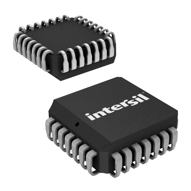
- Part No.:
- CS82C59A-12Z96
- Manufacturer:
- Renesas
- Category:
- Specialized
- Package:
- 28-LCC (J-Lead)
- Datasheet:
-
 CS82C59A-12Z96.pdf
- Description:
- IC INTERFACE SPECIALIZED 28PLCC
- Quantity:
- Payment:

- Shipping:

Inventory:1,861
Please send an inquiry. Send us your inquiry, and we will respond immediately.
Product details
Overview
CS82C59A-12Z96 from Intersil is a CMOS Priority Interrupt Controller designed to manage up to eight vectored, prioritized interrupt requests in 8080/85 and 80C86/88/286-based systems. It operates at 12.5 MHz, features fully static CMOS design, supports cascading to 64 interrupt levels, and delivers TTL-compatible I/O with single 5V supply operation.
For engineers reviewing the CS82C59A-12Z96 datasheet, CS82C59A-12Z96 pinout, CS82C59A-12Z96 application, or CS82C59A-12Z96 equivalent, this device serves as a drop-in replacement for NMOS 8259A in legacy x86 and 8080-family embedded control systems requiring low-power, programmable priority resolution and interrupt vectoring without wait states.
Technical Context
The CS82C59A-12Z96 implements a dual-mode interrupt controller architecture supporting both edge-triggered and level-triggered IR inputs, with configurable priority resolution (fully nested, rotating, or special mask modes) and dynamic reprogramming via Initialization Command Words (ICW1–ICW4) and Operation Command Words (OCW1–OCW3). Its internal registers - Interrupt Request Register (IRR), In-Service Register (ISR), and Interrupt Mask Register (IMR) - enable real-time arbitration and masking of eight asynchronous interrupt sources.
It interfaces directly with 8-bit data buses using standard RD/WR/CS/A0 control signals, provides three cascade lines (CAS0–CAS2) for master/slave configuration, and outputs either CALL opcodes (for 8080/85) or vector bytes (for 80C86/88/286) on INTA acknowledgment. The SP/EN pin supports buffered mode transceiver control or slave identification.
Key Specifications
| Parameter | Value and Actual Design Meaning |
|---|---|
| Operating Frequency | 12.5 MHz maximum - enables "no wait-state" operation with 12.5 MHz 80C286 CPUs. |
| Supply Voltage | Single 5 V ±10% - eliminates need for dual-rail supplies in legacy microprocessor systems. |
| Quiescent Current | ≤10 µA - ensures ultra-low standby power in battery-backed or power-sensitive industrial controllers. |
| Active Current | ≤1 mA/MHz - scales linearly with clock frequency, simplifying thermal budgeting in dense PCB layouts. |
| Interrupt Inputs | 8 IR pins (IR0–IR7) with internal pull-ups - reduces external component count and supports direct connection to open-collector peripherals. |
| Cascade Capability | Up to 64 interrupt levels via CAS0–CAS2 - allows hierarchical expansion without external logic or glue ICs. |
| Compatibility | PIN-compatible with NMOS 8259A - permits direct PCB-level replacement in existing designs. |
Pinout & Package
CS82C59A-12Z96 is housed in a 28-lead Plastic Leaded Chip Carrier (PLCC) package with Pb-free matte tin terminations, RoHS compliant, supplied in tape-and-reel format (96 units per reel).
| Pin/Terminal | Circuit Role | Design Meaning |
|---|---|---|
| VCC (Pin 28) | Power Supply | +5 V supply input; requires 0.1 µF decoupling capacitor to GND (Pin 14) for noise suppression. |
| GND (Pin 14) | Ground Reference | System ground return path; shared reference for all digital I/O and internal logic. |
| CS (Pin 1) | Chip Select | Active-low enable for RD/WR operations; INTA remains functional regardless of CS state. |
| RD (Pin 2) | Read Control | Active-low signal enabling status register (IRR/ISR/IMR) readout onto D7–D0 bus. |
| WR (Pin 3) | Write Control | Active-low signal enabling command word (ICW/OCW) writes to internal registers. |
| A0 (Pin 4) | Address Select | Distinguishes command vs. status register access; tied to CPU A0 (or A1 for 80C86/88). |
| D7–D0 (Pins 5–12) | Bidirectional Data Bus | 8-bit interface for command loading, status reading, and interrupt vector transmission. |
| INT (Pin 13) | Interrupt Output | Open-drain compatible output driving CPU INTR; VOH meets 8080/8085/8086 input thresholds. |
| INTA (Pin 15) | Interrupt Acknowledge | Input signaling CPU readiness; triggers vector byte or CALL opcode output on D7–D0. |
| IR0–IR7 (Pins 16–19, 21–24) | Interrupt Request Inputs | Asynchronous inputs with internal pull-ups; support edge- or level-triggered assertion per mode config. |
| CAS0–CAS2 (Pins 25–27) | Cascade Interface | Master outputs / slave inputs for multi-controller coordination; define slave ID and routing path. |
| SP/EN (Pin 20) | Slave Program / Enable | Configurable as input (SP=0/1 for master/slave) or output (buffer enable in buffered mode). |
Key Features
| Feature | Design Value |
|---|---|
| Static CMOS Architecture | Enables zero-hold-time operation and eliminates refresh requirements in embedded control firmware. |
| Two Microprocessor Modes | Software-selectable 8080/85 (CALL + 2-byte address) or 80C86/88/286 (single vector byte) response timing. |
| Programmable Trigger Mode | LTIM bit selects edge-triggered (default) or level-triggered interrupt capture for mixed-signal peripheral interfacing. |
| Dynamic Priority Reconfiguration | Rotation, special mask, and polled modes allow runtime adaptation to changing system service demands. |
| Full Cascading Support | No external logic needed to expand beyond 8 interrupts - CAS lines handle ID matching and vector routing automatically. |
Applications
| Industrial PLC Backplane | Legacy x86 SBC Interrupt Management |
|---|---|
Use Scenario: Centralized I/O module in programmable logic controller chassis handling discrete sensor inputs and actuator outputs across multiple slots. IC Role / Device Role / Timing Role: Priority arbiter and vector generator for up to eight slot-specific interrupt sources; synchronizes with 80C86 CPU via INT/INTA handshake. Use Value: Eliminates polling overhead, reduces CPU load by >70% versus software-driven interrupt scanning, and maintains deterministic response latency under heavy I/O load. |
Use Scenario: Real-time control board based on 80286 CPU running DOS-based motion control firmware with multiple serial, timer, and DMA channels. IC Role / Device Role / Timing Role: System-level interrupt controller managing IRQ0–IRQ7 assignments for UART, PIT, and DMA controller; configured in fully nested mode. Use Value: Enables precise, hardware-enforced priority ordering between time-critical motion commands and background diagnostics without software intervention. |
| Avionics Maintenance Terminal | Military Communications Chassis |
Use Scenario: Ruggedized field diagnostic unit interfacing with legacy avionics LRUs via MIL-STD-1553B and discrete discretes. IC Role / Device Role / Timing Role: Edge-triggered interrupt aggregator for fault-reporting discretes; operates in 8085-compatible mode for compatibility with aging flight software. Use Value: Provides deterministic, sub-2 µs interrupt latency from discrete assertion to CPU vector fetch - critical for Class C airborne system certification. |
Use Scenario: Secure radio chassis with multiple encryption modules, RF front-ends, and crypto processors sharing a common 80C286 host. IC Role / Device Role / Timing Role: Cascaded master/slave configuration handling 32+ interrupt sources across four CS82C59A-12Z96 devices in military temperature range (-40°C to +85°C). Use Value: Delivers guaranteed interrupt delivery under EMI stress and wide-temperature operation, validated per MIL-STD-883 Class B screening. |
Equivalent & Alternatives
The following parts are listed as comparable options for similar priority interrupt controller applications.
| Alternative Part | Technical Difference | Application Difference | Selection Advice |
|---|---|---|---|
| CS82C59AZ96 | Same 28-lead PLCC package, Pb-free, tape-and-reel; identical 12.5 MHz speed grade and electrical specs. | No functional difference; CS82C59A-12Z96 superseded CS82C59AZ96 per Intersil ordering guide (FN2784 Rev 6.00, p.2). | Select CS82C59A-12Z96 for new designs requiring latest qualified lot traceability and RoHS-compliant manufacturing. |
| IS82C59A-12Z96 | Same die and functionality, but rated for -40°C to +85°C industrial temperature range (vs. 0°C to +70°C for CS82C59A-12Z96). | Required for extended-temperature deployments such as outdoor base stations or vehicle-mounted terminals. | Choose IS82C59A-12Z96 only when operating ambient exceeds +70°C or drops below 0°C; otherwise CS82C59A-12Z96 is cost-optimized. |
Compared with CS82C59AZ96, CS82C59A-12Z96 offers updated process qualification and packaging documentation; compared with IS82C59A-12Z96, it trades extended temperature capability for lower unit cost and tighter supply chain availability in commercial-grade applications.
Availability
CS82C59A-12Z96 is available at Aetrix Electronics and suitable for industrial PLC backplanes, legacy x86 single-board computers, avionics maintenance terminals, and military communications chassis requiring stable component supply over extended production lifecycles.
Supply support for CS82C59A-12Z96 includes scheduled delivery planning, volume procurement assistance, BOM continuity management, traceable sourcing, and lifecycle availability coordination for OEM customers, industrial embedded developers, connected-device designers, and electronics production programs.
Manufacturer
Intersil Corporation (now part of Renesas Electronics) is a U.S.-based semiconductor company specializing in high-reliability analog and mixed-signal ICs for industrial, aerospace, and defense applications.
The 82C59A family was developed to replace power-hungry NMOS interrupt controllers in 1980s-era microcomputer systems, delivering CMOS efficiency while maintaining full software and pin compatibility with the industry-standard 8259A.
FAQ
What is the maximum clock frequency supported by CS82C59A-12Z96?
The CS82C59A-12Z96 is rated for operation up to 12.5 MHz, enabling "no wait-state" performance with 12.5 MHz 80C286 processors. This speed grade is confirmed in the Intersil FN2784 Rev 6.00 datasheet (p.1) and distinguishes it from 5 MHz and 8 MHz variants. Exceeding 12.5 MHz may result in timing violations during ICW/OCW writes or INTA response cycles.
Is CS82C59A-12Z96 pin-compatible with the original NMOS 8259A?
Yes, CS82C59A-12Z96 is explicitly designed as a pin-compatible, functionally equivalent CMOS replacement for the NMOS 8259A. The datasheet confirms identical pinout, voltage levels, and timing behavior (FN2784 Rev 6.00, p.1), allowing direct PCB-level substitution without layout changes or signal integrity revalidation.
Does CS82C59A-12Z96 support both 8080/85 and 80C86/88 microprocessor modes?
Yes, CS82C59A-12Z96 supports dual microprocessor modes selectable via ICW4's μPM bit: μPM = 0 configures 8080/85 mode (3-byte CALL + address), while μPM = 1 configures 80C86/88/286 mode (single vector byte). This is documented in the Functional Description (p.5) and ICW4 format (p.10) of FN2784 Rev 6.00.
What package type and lead finish does CS82C59A-12Z96 use?
CS82C59A-12Z96 uses a 28-lead Plastic Leaded Chip Carrier (PLCC) package with Pb-free matte tin termination, RoHS compliant, supplied in tape-and-reel format (96 units per reel). This is specified in the Ordering Information table (p.2) and marked as "Pb-Free" in the package notes (p.2).
Can CS82C59A-12Z96 be cascaded to support more than eight interrupt sources?
Yes, CS82C59A-12Z96 supports cascading via CAS0–CAS2 lines to expand interrupt capacity to 64 levels using multiple devices. The master/slave configuration is controlled through ICW3 and ICW4, and no additional external logic is required - a capability verified in the Functional Diagram (p.3) and Cascading section (p.6) of FN2784 Rev 6.00.
CS82C59A-12Z96 Specifications
- Product attributes
- Attribute value
- Manufacturer:
- Renesas
- Series:
- -
- Package/Case:
- 28-LCC (J-Lead)
- Packaging:
- Tape & Reel (TR)
- Product Status:
- Active
- Applications:
- -
- Interface:
- System Bus
- Voltage - Supply:
- 4.5V ~ 5.5V
- Supplier Device Package:
- 28-PLCC (11.51x11.51)
- Grade:
- -
- Qualification:
- -
- Mounting Type:
- Surface Mount
CS82C59A-12Z96 FAQ
1.How can I place an order for CS82C59A-12Z96 through Aetrix?
Please submit a Request for Quotation (RFQ) for CS82C59A-12Z96 on Aetrix. Our sales agent will provide a competitive quotation and guide you through the order confirmation once you accept the terms.
2.Are the price and stock information for CS82C59A-12Z96 reliable?
The price and inventory of CS82C59A-12Z96 are updated periodically and may fluctuate due to market conditions. Stock and pricing data are typically refreshed every 24 hours. Quotation validity for CS82C59A-12Z96 is usually 5 days.
3.What payment methods are accepted for CS82C59A-12Z96?
We accept Wire Transfer, PayPal, Credit Card, Western Union, MoneyGram, and Escrow for CS82C59A-12Z96 transactions.
Note: Certain payment methods may incur a processing fee.
4.How is shipping managed for CS82C59A-12Z96?
CS82C59A-12Z96 orders can be shipped via leading logistics carriers, including DHL, UPS, FedEx, TNT, or Registered Mail.
Once your CS82C59A-12Z96 order is processed, you will receive an email with the shipment details and tracking number.
Note: Tracking information may take up to 24 hours to appear. Express delivery typically takes 3–5 business days.
5.How can I obtain technical support or documentation for CS82C59A-12Z96?
For technical support, including CS82C59A-12Z96 datasheets, pinout diagrams, or application guidance, please contact our engineering support team. They can provide detailed documentation and assistance for your CS82C59A-12Z96 requirements.
6.How does Aetrix verify that CS82C59A-12Z96 is sourced from the original manufacturer or authorized distributors?
All CS82C59A-12Z96 products on Aetrix are procured from qualified distributors and authorized channels. Our dedicated quality assurance team conducts strict verification, including traceability checks and, if necessary, third-party testing. This ensures that CS82C59A-12Z96 meets industry standards.
7.What is the process for return or replacement of CS82C59A-12Z96?
All CS82C59A-12Z96 units undergo pre-shipment inspection (PSI). If there is an issue with CS82C59A-12Z96, returns or replacements are accepted under the following conditions:
1.Quantity discrepancies, incorrect items, or visible external defects (such as breakage or corrosion), acknowledged by Aetrix.
2.The issue is reported within 90 days of delivery.
3.The CS82C59A-12Z96 part is unused and in its original packaging.
Return procedure for CS82C59A-12Z96:
1.Submit a request within 90 days.
2.Obtain a Return Material Authorization (RMA) from Aetrix.
CS82C59A-12Z96 Tags

-
NVT4857UKAZ
NXP Semiconductors

-
TCA8418RTWR
Texas Instruments

-
PCA9546APWR
Texas Instruments

-
MD0100N8-G
Microchip Technology

-
PCA9548APW,118
NXP Semiconductors

-
PCA9540BDP,118
NXP Semiconductors

-
PCA9548APWR
Texas Instruments

-
PCA9546APW,118
NXP Semiconductors

-
PTN3360DBS,518
NXP Semiconductors

-
PCA9546ABS,118
NXP Semiconductors

-
PCA9518PWR
Texas Instruments

-
PCA9545APW,118
NXP Semiconductors
Tech Hub

A practical engineering and sourcing framework covering lifecycle verification, lifetime-buy calculations, replacement qualification, supplier checks and counterfeit-risk controls.

TTL and CMOS logic families differ in thresholds, loading, output drive, power and timing. This engineering guide compares 74HC and 74HCT, calculates noise margins and checks 3.3 V/5 V compatibility.

A practical engineering guide to 3.3V and 5V logic compatibility, input thresholds, resistor dividers, translator ICs, MOSFET level shifting, I2C pull-ups, timing limits and power-sequencing risks.

The 74HC595 uses push-pull logic outputs, while the TPIC6B595 uses 50 V open-drain DMOS sinks for higher-power loads. This guide compares timing, current limits, 3.3 V interfacing, load wiring, thermal…

The 74HC595 converts serial data into eight stable parallel outputs. This guide covers pin functions, shift and storage timing, OE and MR behavior, drive-current limits, cascading, voltage compatibilit…

A technical comparison of level-sensitive latches and edge-triggered flip-flops, covering timing windows, setup and hold limits, master–slave operation, time borrowing, race-through, HDL inference and…

A D latch stores one bit while Enable controls when data can pass. This reference covers gate-level operation, truth tables, transparency, setup and hold timing, LE versus OE, common ICs and practical …

An SR latch stores one bit through cross-coupled feedback. This engineering reference covers NOR and NAND implementations, truth tables, forbidden-state recovery, gated operation, switch debouncing, fa…

Latch circuits retain one bit through feedback. This technical reference covers SR and D latches, truth tables, transparency, timing limits, latch-versus-flip-flop behavior, applications and common log…

An engineering guide to LED driver operation, constant-current and constant-voltage outputs, linear and switching topologies, dimming, IC selection, calculations, replacement compatibility, and fault c…


