
 My Inquiry
 My Account


Renesas CS82C59AZ96
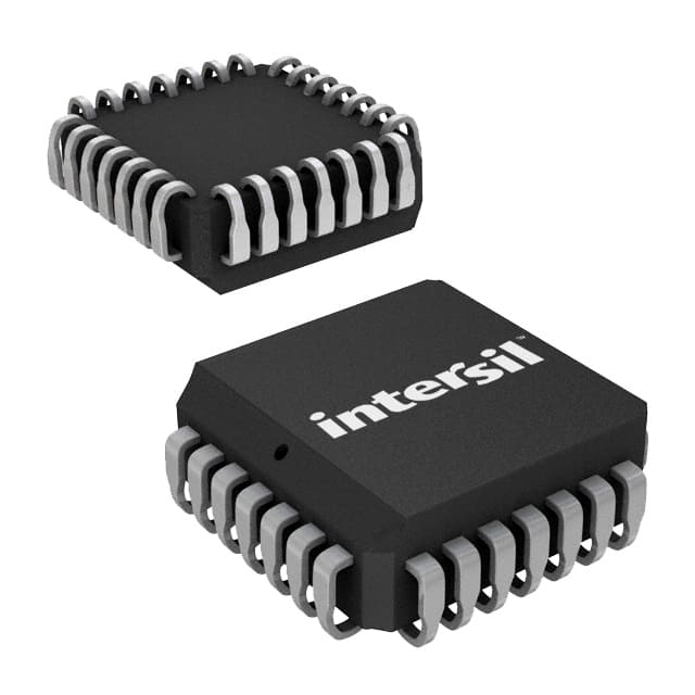
- Part No.:
- CS82C59AZ96
- Manufacturer:
- Renesas
- Category:
- Specialized
- Package:
- 28-LCC (J-Lead)
- Datasheet:
-
 CS82C59AZ96.pdf
- Description:
- IC INTERFACE SPECIALIZED 28PLCC
- Quantity:
- Payment:

- Shipping:

Inventory:2,914
Please send an inquiry. Send us your inquiry, and we will respond immediately.
Product details
Overview
CS82C59AZ96 from Intersil is a CMOS Priority Interrupt Controller designed to offload interrupt management from 8080/85, 8086/88, and 80C286-based microcomputer systems. It handles up to eight vectored priority interrupt sources, supports cascading to 64 levels, operates at 12.5MHz max, features fully static CMOS design, and uses a single +5V supply with <10µA standby current.
For engineers reviewing the CS82C59AZ96 datasheet, CS82C59AZ96 pinout, CS82C59AZ96 application, or CS82C59AZ96 equivalent, this device serves as a drop-in replacement for legacy NMOS 8259A in industrial control, retro-computing, and embedded real-time systems requiring deterministic, low-power interrupt arbitration with full TTL compatibility and programmable priority modes.
Technical Context
The CS82C59AZ96 implements dual-mode operation-fully compatible with both 8080/85 (3-interrupt-acknowledge cycle, CALL opcode output) and 80C86/88/286 (2-cycle, vector-only response) microprocessor buses. Its internal architecture includes separate Interrupt Request (IRR), In-Service (ISR), and Mask (IMR) registers, priority resolver logic, and cascade buffer/comparator for master/slave configuration via CAS0–CAS2 lines.
It supports edge-triggered and level-triggered interrupt inputs (IR0–IR7), programmable initialization command words (ICW1–ICW4), and operation command words (OCW1–OCW3) for dynamic mode selection-including fully nested, rotating priority, special mask, and polled modes-all controlled via 8-bit bidirectional data bus (D0–D7), address line A0, and standard RD/WR/CS timing.
Key Specifications
| Parameter | Value and Actual Design Meaning |
|---|---|
| Max Clock Frequency | 12.5 MHz - enables "no wait-state" operation with 12.5MHz 80C286 and 8MHz 80C86/88 CPUs |
| Interrupt Inputs | 8 (IR0–IR7) - supports asynchronous edge- or level-triggered requests with internal pull-ups |
| Supply Voltage | +5 V ±10% - single-rail operation compatible with legacy TTL/CMOS logic families |
| Standby Current | ≤10 µA - ultra-low ICCSB enables power-sensitive embedded and battery-backed systems |
| Operating Temperature | 0°C to +70°C - commercial-grade range suitable for industrial PC and control chassis environments |
| Cascade Capacity | Up to 64 levels - achieved by daisy-chaining multiple CS82C59AZ96 units without external logic |
| Package Type | 28-lead PLCC (Pb-free, tape-and-reel) - surface-mount footprint with thermal and mechanical reliability for reflow assembly |
Pinout & Package
CS82C59AZ96 is housed in a 28-lead Plastic Leaded Chip Carrier (PLCC) package, Pb-free compliant per RoHS, supplied in tape-and-reel format (96 units per reel). The package is lead-free annealed with 100% matte tin termination, rated for MSL3 reflow compatibility.
| Pin/Terminal | Circuit Role | Design Meaning |
|---|---|---|
| VCC (Pin 28) | Power Supply Input | +5V main supply; requires 0.1µF decoupling capacitor to GND (Pin 14) |
| GND (Pin 14) | Ground Reference | Common return path for all digital and internal logic circuits |
| CS (Pin 1) | Chip Select | Active-low enable for RD/WR operations; INTA remains functional regardless of CS state |
| RD (Pin 2) | Read Control | Active-low signal enabling status register (IRR/ISR/IMR) readout onto D0–D7 bus |
| WR (Pin 3) | Write Control | Active-low signal enabling ICW/OCW loading into internal command registers |
| A0 (Pin 4) | Address Select | Distinguishes between command register (A0=0) and data/status register (A0=1) access |
| D0–D7 (Pins 5–12) | Bidirectional Data Bus | Transfers initialization commands, operation commands, interrupt vectors, and status data |
| INT (Pin 13) | Interrupt Output | Open-collector-compatible active-high signal to CPU's INTR pin; fully TTL-level compliant |
| INTA (Pin 15) | Interrupt Acknowledge Input | Active-low CPU signal triggering vector release on D0–D7 during interrupt sequence |
| IR0–IR7 (Pins 16–18, 20–23, 25–27) | Interrupt Request Inputs | Asynchronous inputs supporting edge- or level-triggered service requests; internally pulled up |
| CAS0–CAS2 (Pins 19, 24, 28) | Cascade Interface | Master outputs / slave inputs for multi-controller arbitration and vector routing in cascaded systems |
| SP/EN (Pin 26) | Slave Program / Enable | Configurable I/O: input for master/slave ID (SP=1/master, SP=0/slave); output for transceiver enable in buffered mode |
Key Features
| Feature | Design Value |
|---|---|
| PIN-Compatible NMOS Replacement | Direct drop-in substitute for 8259A with identical pinout, timing, and register mapping-enables legacy system upgrades without PCB changes |
| Two Microprocessor Mode Support | Software-selectable 8080/85 (3-cycle CALL + vector) or 80C86/88/286 (2-cycle vector-only) response-preserves firmware compatibility across architectures |
| Programmable Priority Architecture | Eight-level priority resolution with dynamic reconfiguration via OCWs-supports fully nested, rotating, and special mask modes for flexible system-level interrupt policy |
| Low-Power Static CMOS Design | 10µA max standby current and 1mA/MHz active current-reduces thermal load and extends uptime in fanless or sealed enclosures |
| Expandable Cascade Interface | CAS0–CAS2 lines enable seamless master/slave chaining up to 64 interrupt levels using only native hardware-no glue logic required |
Applications
| Industrial PLC Backplane | Retro Computing Motherboard |
|---|---|
|
Use Scenario: Real-time I/O expansion in programmable logic controllers where multiple sensor/actuator modules assert interrupts asynchronously. IC Role / Device Role / Timing Role: Centralized interrupt arbiter that prioritizes and vectors IR0–IR7 requests from discrete I/O cards to the main CPU, synchronizing with scan-cycle timing. Use Value: Eliminates CPU polling overhead, ensuring sub-millisecond response to critical field events while maintaining deterministic scan-loop execution. |
Use Scenario: Interrupt management in 8086/88-based single-board computers or vintage PC clones requiring backward-compatible peripheral support. IC Role / Device Role / Timing Role: Legacy-compatible interrupt controller interfacing keyboard, timer, serial UART, and DMA channels to the CPU's INTR line. Use Value: Enables faithful reproduction of original IBM PC/XT interrupt vectoring behavior-including CALL opcode generation and cascaded PIC handshaking-without firmware modification. |
| Embedded Motion Controller | Military Avionics Subsystem |
|
Use Scenario: Coordinating encoder feedback, limit switch triggers, and servo fault signals in closed-loop motor drives operating under strict real-time deadlines. IC Role / Device Role / Timing Role: Priority-resolving interrupt hub that routes time-critical axis faults (IR0) ahead of lower-priority position updates (IR6–IR7) to the DSP or microcontroller. Use Value: Guarantees worst-case interrupt latency ≤2.5 µs at 12.5MHz, preventing motion loss during high-speed trajectory execution. |
Use Scenario: Fault monitoring and health reporting in airborne mission computers where redundant sensor inputs require deterministic interrupt handling under EMI stress. IC Role / Device Role / Timing Role: Radiation-tolerant interrupt manager (via IS82C59A derivative lineage) aggregating discrete fault flags from navigation, comms, and power modules. Use Value: Provides fail-safe interrupt masking and priority override via OCW1/OCW2-ensuring critical flight-critical alerts preempt non-essential telemetry interrupts. |
Equivalent & Alternatives
The following parts are listed as comparable options for similar priority interrupt controller applications.
| Alternative Part | Technical Difference | Application Difference | Selection Advice |
|---|---|---|---|
| CS82C59A-12Z96 | 12.5MHz version with identical PLCC-28 Pb-free tape-and-reel packaging; same pinout and register set | No functional difference-only frequency binning variant; superseded by CS82C59AZ96 per Intersil ordering guide | Select CS82C59AZ96 for guaranteed availability and latest RoHS compliance; CS82C59A-12Z96 may be limited-stock legacy stock |
| IS82C59AZX96 | Extended temperature grade (–40°C to +85°C); otherwise identical architecture, pinout, and command set | Required for avionics, outdoor industrial, or automotive under-hood applications where ambient exceeds +70°C | Choose IS82C59AZX96 when operating outside commercial temperature range; CS82C59AZ96 is optimized for cost-sensitive commercial/industrial chassis use |
Compared with CS82C59A-12Z96, CS82C59AZ96 offers updated manufacturing traceability and full RoHS documentation; versus IS82C59AZX96, it trades extended temperature capability for lower unit cost and broader commercial supply chain alignment-making it the preferred choice for fixed-temperature embedded platforms.
Availability
CS82C59AZ96 is available at Aetrix Electronics and suitable for industrial PLC backplanes, retro computing motherboards, and embedded motion controllers requiring stable component supply, long-term obsolescence mitigation, and verified legacy interface compatibility.
Supply support for CS82C59AZ96 includes scheduled delivery planning, volume procurement assistance, BOM continuity management, traceable sourcing, and lifecycle availability coordination for OEM customers, industrial embedded developers, connected-device designers, and electronics production programs.
Manufacturer
Intersil Corporation (now part of Renesas Electronics) is a U.S.-based semiconductor company specializing in high-performance analog and mixed-signal ICs for industrial, computing, and communications markets.
The 82C59A family was developed to deliver CMOS power efficiency and speed parity with legacy NMOS interrupt controllers-targeting retro-computing restoration, industrial control upgrades, and embedded systems needing deterministic, software-configurable interrupt arbitration.
FAQ
What is the maximum operating frequency of the CS82C59AZ96?
The CS82C59AZ96 supports a maximum clock frequency of 12.5 MHz, enabling no-wait-state operation with 12.5 MHz 80C286 and 8 MHz 80C86/88 microprocessors. This rating is validated across the full 0°C to +70°C commercial temperature range and reflects guaranteed timing margins for setup/hold and propagation delays in both 8080/85 and 80C86/88/286 bus modes.
Is the CS82C59AZ96 pin-compatible with the original NMOS 8259A?
Yes, the CS82C59AZ96 is fully pin-compatible with the NMOS 8259A, sharing identical pin assignments, electrical signaling levels (TTL-compatible), and register mapping. This allows direct replacement in legacy designs without PCB layout changes, provided the +5V supply and decoupling meet CMOS drive requirements.
Does the CS82C59AZ96 support both edge-triggered and level-triggered interrupt inputs?
Yes, the CS82C59AZ96 supports both edge-triggered (default after reset) and level-triggered interrupt modes via the LTIM bit in ICW1. When LTIM = 1, internal edge-detect circuitry is disabled, allowing sustained high-level assertions on IR0–IR7 to maintain interrupt request until acknowledged-critical for slow or noisy peripheral interfaces.
How does cascading work with multiple CS82C59AZ96 devices?
Cascading up to 64 interrupt levels is achieved using the CAS0–CAS2 lines: one CS82C59AZ96 acts as master (SP/EN = 1), others as slaves (SP/EN = 0). The master asserts slave ID bits on CAS0–CAS2 during INTA; the matching slave responds with its programmed vector. No external logic is needed-only proper ICW3/ICW4 configuration distinguishes master vs. slave roles.
What package type and environmental compliance does the CS82C59AZ96 have?
The CS82C59AZ96 is supplied in a 28-lead Pb-free PLCC package (RoHS compliant), delivered in tape-and-reel format (96 units per reel). It uses 100% matte tin termination and is qualified for MSL3 reflow per IPC/JEDEC J-STD-020, making it suitable for modern automated SMT assembly without lead-free process compromises.
CS82C59AZ96 Specifications
- Product attributes
- Attribute value
- Manufacturer:
- Renesas
- Series:
- -
- Package/Case:
- 28-LCC (J-Lead)
- Packaging:
- Tape & Reel (TR)
- Product Status:
- Active
- Applications:
- -
- Interface:
- System Bus
- Voltage - Supply:
- 4.5V ~ 5.5V
- Supplier Device Package:
- 28-PLCC (11.51x11.51)
- Grade:
- -
- Qualification:
- -
- Mounting Type:
- Surface Mount
CS82C59AZ96 FAQ
1.How can I place an order for CS82C59AZ96 through Aetrix?
Please submit a Request for Quotation (RFQ) for CS82C59AZ96 on Aetrix. Our sales agent will provide a competitive quotation and guide you through the order confirmation once you accept the terms.
2.Are the price and stock information for CS82C59AZ96 reliable?
The price and inventory of CS82C59AZ96 are updated periodically and may fluctuate due to market conditions. Stock and pricing data are typically refreshed every 24 hours. Quotation validity for CS82C59AZ96 is usually 5 days.
3.What payment methods are accepted for CS82C59AZ96?
We accept Wire Transfer, PayPal, Credit Card, Western Union, MoneyGram, and Escrow for CS82C59AZ96 transactions.
Note: Certain payment methods may incur a processing fee.
4.How is shipping managed for CS82C59AZ96?
CS82C59AZ96 orders can be shipped via leading logistics carriers, including DHL, UPS, FedEx, TNT, or Registered Mail.
Once your CS82C59AZ96 order is processed, you will receive an email with the shipment details and tracking number.
Note: Tracking information may take up to 24 hours to appear. Express delivery typically takes 3–5 business days.
5.How can I obtain technical support or documentation for CS82C59AZ96?
For technical support, including CS82C59AZ96 datasheets, pinout diagrams, or application guidance, please contact our engineering support team. They can provide detailed documentation and assistance for your CS82C59AZ96 requirements.
6.How does Aetrix verify that CS82C59AZ96 is sourced from the original manufacturer or authorized distributors?
All CS82C59AZ96 products on Aetrix are procured from qualified distributors and authorized channels. Our dedicated quality assurance team conducts strict verification, including traceability checks and, if necessary, third-party testing. This ensures that CS82C59AZ96 meets industry standards.
7.What is the process for return or replacement of CS82C59AZ96?
All CS82C59AZ96 units undergo pre-shipment inspection (PSI). If there is an issue with CS82C59AZ96, returns or replacements are accepted under the following conditions:
1.Quantity discrepancies, incorrect items, or visible external defects (such as breakage or corrosion), acknowledged by Aetrix.
2.The issue is reported within 90 days of delivery.
3.The CS82C59AZ96 part is unused and in its original packaging.
Return procedure for CS82C59AZ96:
1.Submit a request within 90 days.
2.Obtain a Return Material Authorization (RMA) from Aetrix.
CS82C59AZ96 Tags

-
NVT4857UKAZ
NXP Semiconductors

-
TCA8418RTWR
Texas Instruments

-
PCA9546APWR
Texas Instruments

-
MD0100N8-G
Microchip Technology

-
PCA9548APW,118
NXP Semiconductors

-
PCA9540BDP,118
NXP Semiconductors

-
PCA9548APWR
Texas Instruments

-
PCA9546APW,118
NXP Semiconductors

-
PTN3360DBS,518
NXP Semiconductors

-
PCA9546ABS,118
NXP Semiconductors

-
PCA9518PWR
Texas Instruments

-
PCA9545APW,118
NXP Semiconductors
Tech Hub

TTL and CMOS logic families differ in thresholds, loading, output drive, power and timing. This engineering guide compares 74HC and 74HCT, calculates noise margins and checks 3.3 V/5 V compatibility.

A practical engineering guide to 3.3V and 5V logic compatibility, input thresholds, resistor dividers, translator ICs, MOSFET level shifting, I2C pull-ups, timing limits and power-sequencing risks.

The 74HC595 uses push-pull logic outputs, while the TPIC6B595 uses 50 V open-drain DMOS sinks for higher-power loads. This guide compares timing, current limits, 3.3 V interfacing, load wiring, thermal…

The 74HC595 converts serial data into eight stable parallel outputs. This guide covers pin functions, shift and storage timing, OE and MR behavior, drive-current limits, cascading, voltage compatibilit…

A technical comparison of level-sensitive latches and edge-triggered flip-flops, covering timing windows, setup and hold limits, master–slave operation, time borrowing, race-through, HDL inference and…

A D latch stores one bit while Enable controls when data can pass. This reference covers gate-level operation, truth tables, transparency, setup and hold timing, LE versus OE, common ICs and practical …

An SR latch stores one bit through cross-coupled feedback. This engineering reference covers NOR and NAND implementations, truth tables, forbidden-state recovery, gated operation, switch debouncing, fa…

Latch circuits retain one bit through feedback. This technical reference covers SR and D latches, truth tables, transparency, timing limits, latch-versus-flip-flop behavior, applications and common log…

An engineering guide to LED driver operation, constant-current and constant-voltage outputs, linear and switching topologies, dimming, IC selection, calculations, replacement compatibility, and fault c…

Operational amplifier guide covering op amp basics, feedback, ideal vs real op amps, common configurations, buffer circuits, offset, bias current, gain-bandwidth, slew rate, rail-to-rail limits and sel…


