
 My Inquiry
 My Account


NXP Semiconductors CX24109-11Z,518
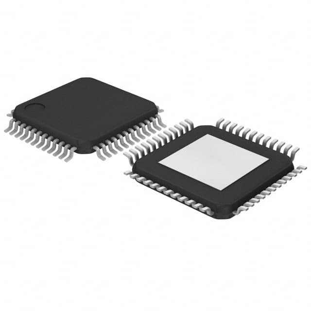
- Part No.:
- CX24109-11Z,518
- Manufacturer:
- NXP Semiconductors
- Category:
- Video Processing
- Package:
- 48-TQFP Exposed Pad
- Datasheet:
-
 CX24109-11Z,518.pdf
- Description:
- IC VIDEO TUNER DIGITAL 48HTQFP
- Quantity:
- Payment:

- Shipping:

Inventory:1,087
Please send an inquiry. Send us your inquiry, and we will respond immediately.
Product details
Overview
CX24109-11Z,518 from NXP Semiconductors is a highly integrated digital satellite tuner IC designed for direct down-conversion of L-band satellite signals (950–2150 MHz) into baseband I/Q outputs. It features zero-IF architecture, integrated LNA and VCO-based synthesizer, single +5 V supply, and 48-pin eTQFP package. Used with CX24121 demodulator, it enables full DVB/DSS-compliant satellite front-end solutions in set-top boxes.
For engineers reviewing the CX24109-11Z,518 datasheet, CX24109-11Z,518 pinout, CX24109-11Z,518 application, or CX24109-11Z,518 equivalent, key selection criteria include RF input frequency range, AGC-controlled 80 dB gain range, I/Q output interface compatibility, PLL programmability via 3-wire serial interface, and thermal performance under continuous satellite signal reception.
Technical Context
The CX24109-11Z,518 implements a zero-IF architecture with quadrature downconversion, eliminating image-reject filtering. Its integrated VCO covers 2200–4400 MHz and divides by 2 or 4 to generate LO frequencies spanning 950–2150 MHz across eight overlapping bands.
AGC control is split between RF (VCA) and baseband (dual VGA) stages, delivering 80 dB total variable gain. Gain is controlled by an analog voltage (0–3 V) from the demodulator IC, with programmable slope/offset per stage via 21-bit serial interface operating up to 1 MHz.
Key Specifications
| Parameter | Value and Actual Design Meaning |
|---|---|
| RF Input Range | 950–2150 MHz L-band; supports full DBS/DVB-S/DSS satellite downlink spectrum without external preselection. |
| LO Generation | VCO + integer-N PLL with 10.111 MHz crystal reference; programmable ÷R (10/20/40), ÷N/A counters, and charge pump currents (1–4 mA). |
| Total Gain Range | 80 dB via combined VCA (RF) and dual VGA (baseband); AGC voltage range: 0–3 V, with gain equations fully documented. |
| Output Interface | Differential I/Q baseband outputs (IOUTP/IOUTN, QOUTP/QOUTN); 1 kΩ//10 pF output impedance; supports balanced or single-ended connection to demodulator. |
| Power Supply | +5 V only; no high-voltage (e.g., 28 V) LNB bias required; 10 VCC pins and 18 GND pins distributed for low-noise layout. |
| Control Interface | 3-wire CMOS serial interface (CLK, DATA, EN); 21-bit word with MSB control bits; max clock rate 1 MHz; latch-on-EN high. |
| Reference Clock Output | CLKREFOUT provides 10.111 MHz system clock to demodulator; load capability: 10 kΩ//20 pF. |
Pinout & Package
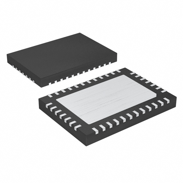
Package: 48-pin eTQFP (enhanced thin quad flat pack), 7 mm × 7 mm, 0.5 mm pitch, exposed thermal pad (GND-connected). Land pattern and mechanical drawing provided in Figure 16 and Figure 17 of datasheet.
| Pin/Terminal | Circuit Role | Design Meaning |
|---|---|---|
| RFIN | RF input | Single-ended 75 Ω L-band input; connects directly to LNB drop cable; requires 75 Ω transmission line routing. |
| IOUTP / IOUTN QOUTP / QOUTN |
Differential I/Q outputs | Baseband analog outputs to demodulator; configurable as balanced (recommended) or single-ended; 1 kΩ//10 pF Zout. |
| AGC | Analog AGC control input | 0–3 V analog voltage from demodulator sets total gain; input impedance 1 MΩ//20 pF; 10 kΩ series resistor recommended. |
| FILTUNE | Filter bandwidth control | Analog voltage (0–3 V) sets tunable low-pass filter –3 dB bandwidth; Zin = 17 kΩ//20 pF; controls anti-aliasing before ADC. |
| CLKREFOUT | Reference clock output | 10.111 MHz CMOS clock for demodulator synchronization; max load 10 kΩ//20 pF; eliminates need for separate crystal. |
| LD | Lock detect output | CMOS-level open-drain output; high = PLL locked; used by host processor or demodulator for tuning confirmation. |
| XTAL1 / XTAL2 | Crystal oscillator inputs | Connects 10.111 MHz fundamental-mode series-resonant crystal; internal oscillator circuit eliminates external components. |
| CLK / DATA / EN | Serial programming interface | 3-wire CMOS bus; EN latches 21-bit word on rising edge; CLK max 1 MHz; DATA MSB-first; all signals 5 V tolerant. |
Key Features
| Feature | Design Value |
|---|---|
| Zero-IF architecture | Eliminates image-reject filters and IF SAW components, reducing BOM count and board area in satellite STBs. |
| Integrated VCO + synthesizer | On-chip 2200–4400 MHz VCO with 8-band selection and ÷2/÷4 dividers enables full 950–2150 MHz coverage without external tuning elements. |
| 80 dB AGC range | Combines VCA (RF) and dual VGA (baseband) stages, enabling robust operation across varying LNB gain and signal strength conditions. |
| Single +5 V supply | Removes need for 28 V LNB bias generation circuitry; simplifies power design and improves safety in consumer equipment. |
| Programmable baseband filter | FILTUNE pin adjusts low-pass filter bandwidth dynamically to match symbol rate (1–45 MSps), optimizing SNR and alias rejection. |
Applications
| DBS Set-Top Box Front End | Digital Satellite Receiver |
|---|---|
Use Scenario: Tuning and downconverting L-band satellite signals (950–2150 MHz) from dish-mounted LNB into baseband I/Q for QPSK demodulation. IC Role / Device Role / Timing Role: Primary RF tuner IC performing direct-conversion, AGC, filtering, and clock distribution in satellite receiver signal chain. Use Value: Enables compact, low-cost, standards-compliant (DVB-S/DSS) front end with minimal external components and no image-reject filters. |
Use Scenario: Receiving encrypted/unencrypted digital video, audio, and data broadcasts from geostationary satellites in commercial or residential environments. IC Role / Device Role / Timing Role: Core tuner component providing stable I/Q outputs synchronized to CLKREFOUT for downstream FEC decoding and MPEG processing. Use Value: Supports symbol rates from 1–45 MSps with programmable filter bandwidth and gain slope, ensuring interoperability across global satellite services. |
| Digital VCR Satellite Recording | Commercial Video Distribution Hub |
Use Scenario: Capturing live satellite TV streams for time-shifted playback or archival recording in digital video recorders. IC Role / Device Role / Timing Role: High-linearity tuner delivering low-noise I/Q signals to ADC-equipped recording subsystems with precise AGC tracking. Use Value: Maintains >50 dB SFDR over full gain range and temperature, preserving signal fidelity during long-duration recording sessions. |
Use Scenario: Aggregating multiple satellite feeds in headend or broadcast contribution systems for redistribution over IP or coaxial networks. IC Role / Device Role / Timing Role: Multi-channel tuner element in modular front-end chassis, leveraging shared 10.111 MHz reference and serial control bus. Use Value: Reduces system-level clock jitter and simplifies synchronization across channels via integrated CLKREFOUT and deterministic PLL lock timing. |
Equivalent & Alternatives
The following parts are listed as comparable options for similar digital satellite tuner applications.
| Alternative Part | Technical Difference | Application Difference | Selection Advice |
|---|---|---|---|
| STV0297D | Single +3.3 V supply; supports DVB-S2; includes integrated LNB power control; different pinout and register map. | Targeted at newer DVB-S2 receivers requiring higher symbol rates (>45 MSps) and LNB voltage switching. | Choose STV0297D when upgrading to DVB-S2 or requiring 3.3 V system integration; not pin-compatible with CX24109-11Z,518. |
| MT2060 | ZIF architecture; requires external image-reject filter; 3.3 V core / 5 V analog supply; different AGC structure (digital-only). | Suitable for hybrid terrestrial/satellite tuners where ZIF offers better adjacent channel rejection in noisy RF environments. | Choose MT2060 when co-location with strong terrestrial signals demands superior image rejection; layout and filtering requirements differ significantly. |
Compared with STV0297D and MT2060, the CX24109-11Z,518 delivers lower BOM cost through zero-IF integration and single 5 V supply, but lacks DVB-S2 support and requires external loop filter tuning-making it optimal for cost-sensitive DVB-S legacy STB designs.
Availability
CX24109-11Z,518 is available at Aetrix Electronics and suitable for DBS set-top boxes, digital satellite receivers, digital VCRs, and commercial video distribution hubs requiring stable component supply and long-lifecycle support.
Supply support for CX24109-11Z,518 includes scheduled delivery planning, volume procurement assistance, BOM continuity management, traceable sourcing, and lifecycle availability coordination for OEM customers, industrial embedded developers, connected-device designers, and electronics production programs.
Manufacturer
NXP Semiconductors is a global semiconductor company headquartered in Eindhoven, Netherlands, specializing in secure connectivity solutions for automotive, industrial, and consumer applications.
The CX24109-11Z,518 belongs to NXP's satellite communications product line, designed specifically for high-volume, cost-optimized digital satellite receiver front ends compliant with DVB and DSS standards.
FAQ
What is the RF input frequency range supported by the CX24109-11Z,518?
The CX24109-11Z,518 supports an RF input frequency range of 950 MHz to 2150 MHz, covering the full L-band spectrum used by DBS and DVB-S satellite services. This range is achieved using an internal VCO with eight overlapping bands and programmable ÷2/÷4 division, enabling continuous tuning without gaps across voltage, temperature, and process variations.
Does the CX24109-11Z,518 require an external crystal oscillator?
No-the CX24109-11Z,518 integrates a complete crystal oscillator circuit. A 10.111 MHz fundamental-mode series-resonant crystal is connected between XTAL1 and XTAL2 pins, and the internal oscillator generates the system clock used for PLL operation and CLKREFOUT output. No external oscillator IC or buffer is needed.
How is AGC implemented in the CX24109-11Z,518?
The CX24109-11Z,518 implements a two-stage AGC: a voltage-controlled attenuator (VCA) in the RF path and dual voltage-controlled amplifiers (VGA1/VGA2) in the baseband path, delivering 80 dB total gain range. AGC is controlled by a single analog voltage (0–3 V) applied to the AGC pin, with programmable slope and offset per stage via the 21-bit serial interface.
What output interface does the CX24109-11Z,518 provide for connection to a demodulator?
The CX24109-11Z,518 provides differential I/Q baseband analog outputs: IOUTP/IOUTN and QOUTP/QOUTN. Each pair has 1 kΩ//10 pF output impedance and supports either balanced (recommended) or single-ended connection to the demodulator IC. It also supplies a synchronized 10.111 MHz CLKREFOUT clock signal.
Is the CX24109-11Z,518 compatible with DVB-S2 standards?
No-the CX24109-11Z,518 is designed for DVB-S and DSS standards only. It supports symbol rates up to 45 MSps but lacks the enhanced modulation schemes (e.g., 8PSK), adaptive coding, and higher symbol rate capability required for DVB-S2 compliance. For DVB-S2, consider alternatives like STV0297D.
CX24109-11Z,518 Specifications
- Product attributes
- Attribute value
- Manufacturer:
- NXP Semiconductors
- Series:
- -
- Package/Case:
- 48-TQFP Exposed Pad
- Packaging:
- Tape & Reel (TR)
- Product Status:
- Obsolete
- Function:
- Tuner
- Applications:
- Consumer Video
- Standards:
- -
- Control Interface:
- Serial
- Voltage - Supply:
- 4.75V ~ 5.25V
- Mounting Type:
- Surface Mount
- Grade:
- -
- Qualification:
- -
- Supplier Device Package:
- 48-HTQFP (7x7)
CX24109-11Z,518 FAQ
1.How can I place an order for CX24109-11Z,518 through Aetrix?
Please submit a Request for Quotation (RFQ) for CX24109-11Z,518 on Aetrix. Our sales agent will provide a competitive quotation and guide you through the order confirmation once you accept the terms.
2.Are the price and stock information for CX24109-11Z,518 reliable?
The price and inventory of CX24109-11Z,518 are updated periodically and may fluctuate due to market conditions. Stock and pricing data are typically refreshed every 24 hours. Quotation validity for CX24109-11Z,518 is usually 5 days.
3.What payment methods are accepted for CX24109-11Z,518?
We accept Wire Transfer, PayPal, Credit Card, Western Union, MoneyGram, and Escrow for CX24109-11Z,518 transactions.
Note: Certain payment methods may incur a processing fee.
4.How is shipping managed for CX24109-11Z,518?
CX24109-11Z,518 orders can be shipped via leading logistics carriers, including DHL, UPS, FedEx, TNT, or Registered Mail.
Once your CX24109-11Z,518 order is processed, you will receive an email with the shipment details and tracking number.
Note: Tracking information may take up to 24 hours to appear. Express delivery typically takes 3–5 business days.
5.How can I obtain technical support or documentation for CX24109-11Z,518?
For technical support, including CX24109-11Z,518 datasheets, pinout diagrams, or application guidance, please contact our engineering support team. They can provide detailed documentation and assistance for your CX24109-11Z,518 requirements.
6.How does Aetrix verify that CX24109-11Z,518 is sourced from the original manufacturer or authorized distributors?
All CX24109-11Z,518 products on Aetrix are procured from qualified distributors and authorized channels. Our dedicated quality assurance team conducts strict verification, including traceability checks and, if necessary, third-party testing. This ensures that CX24109-11Z,518 meets industry standards.
7.What is the process for return or replacement of CX24109-11Z,518?
All CX24109-11Z,518 units undergo pre-shipment inspection (PSI). If there is an issue with CX24109-11Z,518, returns or replacements are accepted under the following conditions:
1.Quantity discrepancies, incorrect items, or visible external defects (such as breakage or corrosion), acknowledged by Aetrix.
2.The issue is reported within 90 days of delivery.
3.The CX24109-11Z,518 part is unused and in its original packaging.
Return procedure for CX24109-11Z,518:
1.Submit a request within 90 days.
2.Obtain a Return Material Authorization (RMA) from Aetrix.
CX24109-11Z,518 Tags
-
HDMI2C1-6C1
STMicroelectronics
-
ADA4430-1YKSZ-R7
Analog Devices Inc.

-
LM1881MX/NOPB
Texas Instruments

-
SN75DP130SSRGZR
Texas Instruments
-
EQCO30T5.2
Microchip Technology

-
LMH1980MM/NOPB
Texas Instruments
-
EQCO30R5.D
Microchip Technology

-
SII9022ACNU
Lattice Semiconductor Corporation
-
SN65DP159RGZR
Texas Instruments

-
SN65DP159RSBR
Texas Instruments
-
SN65DP141RLJR
Texas Instruments
-
LMH0303SQ/NOPB
Texas Instruments
Tech Hub

A practical engineering guide to 3.3V and 5V logic compatibility, input thresholds, resistor dividers, translator ICs, MOSFET level shifting, I2C pull-ups, timing limits and power-sequencing risks.

The 74HC595 uses push-pull logic outputs, while the TPIC6B595 uses 50 V open-drain DMOS sinks for higher-power loads. This guide compares timing, current limits, 3.3 V interfacing, load wiring, thermal…

The 74HC595 converts serial data into eight stable parallel outputs. This guide covers pin functions, shift and storage timing, OE and MR behavior, drive-current limits, cascading, voltage compatibilit…

A technical comparison of level-sensitive latches and edge-triggered flip-flops, covering timing windows, setup and hold limits, master–slave operation, time borrowing, race-through, HDL inference and…

A D latch stores one bit while Enable controls when data can pass. This reference covers gate-level operation, truth tables, transparency, setup and hold timing, LE versus OE, common ICs and practical …

An SR latch stores one bit through cross-coupled feedback. This engineering reference covers NOR and NAND implementations, truth tables, forbidden-state recovery, gated operation, switch debouncing, fa…

Latch circuits retain one bit through feedback. This technical reference covers SR and D latches, truth tables, transparency, timing limits, latch-versus-flip-flop behavior, applications and common log…

An engineering guide to LED driver operation, constant-current and constant-voltage outputs, linear and switching topologies, dimming, IC selection, calculations, replacement compatibility, and fault c…

Operational amplifier guide covering op amp basics, feedback, ideal vs real op amps, common configurations, buffer circuits, offset, bias current, gain-bandwidth, slew rate, rail-to-rail limits and sel…

Jumper cables guide covering safe connection order, red and black clamp placement, final ground connection, cable gauge, length, clamp quality, copper vs CCA cables, jump starter comparison and battery…


