
 My Inquiry
 My Account


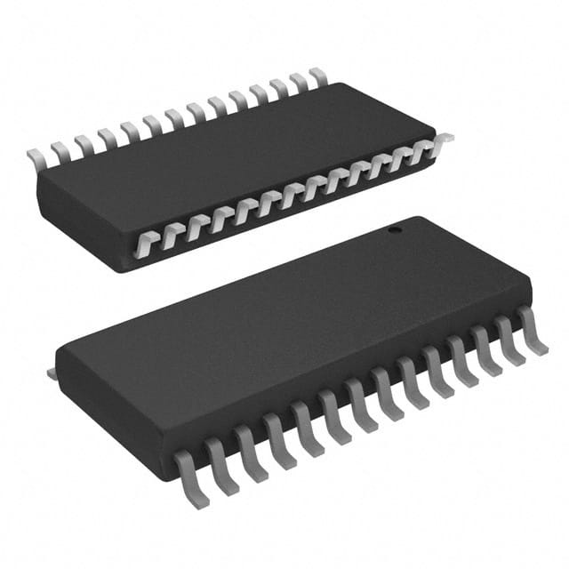
Infineon Technologies CY2313ANZSC-1
- Part No.:
- CY2313ANZSC-1
- Manufacturer:
- Infineon Technologies
- Category:
- Application Specific Clock/Timing
- Package:
- 28-SOIC (0.295", 7.50mm Width)
- Datasheet:
-
 CY2313ANZSC-1.pdf
- Description:
- IC CLK BUFF 13OUT SDRAM 28SOIC
- Quantity:
- Payment:

- Shipping:

Inventory:2,975
Please send an inquiry. Send us your inquiry, and we will respond immediately.
Product details
Overview
CY2313ANZSC-1 from Cypress Semiconductor is a 3.3V, 13-output SDRAM clock buffer designed for desktop PC motherboards supporting up to three DDR SDRAM DIMMs. It delivers low-skew (±250 ps), 100-MHz clock distribution with serial output enable/disable control, integrated I²C-compatible interface (SDATA/SCLK), and dedicated feedback output (SDRAM12) for PLL synchronization in Pentium II–class systems.
For engineers reviewing the CY2313ANZSC-1 datasheet, CY2313ANZSC-1 pinout, CY2313ANZSC-1 application, or CY2313ANZSC-1 equivalent, key selection criteria include 3.3V operation, 13-output fanout with per-channel disable, SOIC-28 package compatibility, and support for high-speed SDRAM timing in legacy x86 desktop platforms.
Technical Context
The CY2313ANZSC-1 implements a single-input, 13-output fanout buffer architecture with internal termination and noise-reduction design features including five VDD/VSS pairs and separate I²C supply rails (VDDIIC/VSSIIC). Its serial interface uses SDATA and SCLK pins with internal pull-ups to configure output enables via three-byte register map.
Each of the 13 SDRAM outputs (SDRAM0–SDRAM12) drives one clock line to memory modules, with SDRAM12 reserved for external PLL feedback. Propagation delay is 1.0–5.0 ns (LH/HL), duty cycle is tightly controlled at 45–55%, and edge rates range from 0.9–4.0 V/ns - all specified under loaded 30-pF conditions at 100 MHz.
Key Specifications
| Parameter | Value and Actual Design Meaning |
|---|---|
| Supply Voltage | 3.135–3.465 V - ensures stable operation across commercial temperature range with ±5% tolerance |
| Max Operating Frequency | 100 MHz - supports Pentium II front-side bus and SDRAM timing requirements |
| Output-to-Output Skew | ±250 ps - guarantees tight phase alignment across all 13 outputs for synchronous memory access |
| Propagation Delay | 1.0–5.0 ns - defines worst-case timing margin between input clock edge and output transition |
| Serial Interface | I²C-compatible SDATA/SCLK with VDDIIC/VSSIIC rails - enables dynamic output enable/disable without hardware rework |
| Load Capacitance | 30 pF - matches standard PCB trace + DIMM stub loading for signal integrity validation |
| Power Supply Pins | 5× VDD / 5× VSS - reduces ground bounce and supply noise in high-fanout clock distribution |
Pinout & Package
Package: 28-pin SOIC (300-mil), surface-mount, Pb-free compliant (S21 footprint).
| Pin/Terminal | Circuit Role | Design Meaning |
|---|---|---|
| BUF_IN (Pin 9) | Input clock reference | Accepts 3.3V CMOS input; threshold at VDD/2; supports up to 100 MHz |
| SDRAM0–SDRAM12 (Pins 2,3,6,7,10,11,12,18,19,22,23,26,27) | Buffered clock outputs | 13 independent 3.3V CMOS outputs; SDRAM12 used for PLL feedback path |
| SDATA (Pin 14), SCLK (Pin 15) | Serial configuration interface | I²C-style control with internal pull-ups; enables per-output enable/disable |
| VDD (Pins 1,5,20,24,28), VSS (Pins 4,8,17,21,25) | Digital power/ground | Five decoupled supply/ground pairs minimize simultaneous switching noise |
| VDDIIC (Pin 13), VSSIIC (Pin 16) | Serial interface supply | Isolated rail prevents I²C activity from disturbing core clock distribution |
Key Features
| Feature | Design Value |
|---|---|
| Per-output enable/disable | Serial register map allows selective activation of any SDRAM output without external logic |
| Low-output skew | ±250 ps matching ensures synchronized clock edges across all DIMM slots |
| Dedicated feedback output | SDRAM12 provides clean, buffered clock signal directly to system PLL for jitter reduction |
| Noise-optimized supply layout | Multiple VDD/VSS pins and separated I²C rails suppress supply-induced jitter and crosstalk |
| Commercial-grade thermal range | 0°C to +70°C ambient operation - validated for desktop motherboard environments |
Applications
| Desktop PC Motherboard Clock Distribution | Pentium II Memory Subsystem |
|---|---|
Use Scenario: Distributing CPU-derived clock signals to three physically separated SDRAM DIMM banks on ATX-form-factor motherboards. IC Role / Device Role / Timing Role: Fanout buffer providing 13 synchronized, low-jitter clock outputs - 12 for DIMM address/control clocks, 1 for PLL feedback. Use Value: Eliminates clock tree skew and enables reliable 100-MHz SDRAM operation without discrete termination or buffering. | Use Scenario: Supporting dual-channel or triple-DIMM configurations in Pentium II–based workstations requiring strict tAC and tCO timing compliance. IC Role / Device Role / Timing Role: Timing hub synchronizing memory clocks with CPU clock domain via feedback loop to CY2280/CY2281 synthesizer. Use Value: Maintains <5 ps added jitter and meets Intel's SDRAM clock skew specification for 66–100 MHz operation. |
| Legacy x86 Platform Upgrade | Industrial Embedded SDRAM Interface |
Use Scenario: Replacing aging clock buffers in serviceable desktop platforms where BIOS does not support modern memory controllers. IC Role / Device Role / Timing Role: Drop-in replacement for CY2310NZ with identical pinout and enhanced serial configurability. Use Value: Enables field-upgradeable output enable/disable without board respin or firmware update. | Use Scenario: Driving SDRAM in ruggedized embedded PCs operating in controlled-temperature industrial enclosures. IC Role / Device Role / Timing Role: Robust clock distribution IC with 150°C junction rating and ESD >2000 V (HBM). Use Value: Provides long-term reliability under thermal cycling and electrical stress where consumer-grade parts fail prematurely. |
Equivalent & Alternatives
The following parts are listed as comparable options for similar SDRAM clock buffer applications.
| Alternative Part | Technical Difference | Application Difference | Selection Advice |
|---|---|---|---|
| CY2310NZ | No serial interface; fixed-output enable; identical pinout and electrical specs except missing SDATA/SCLK/VDDIIC/VSSIIC pins | Lacks runtime output control; requires hardwired enable/disable or external gating logic | Select when serial configuration is unnecessary and cost minimization is critical |
| IDT74FCT162374CPAG | 16-bit non-inverting latch with 3-state outputs; no built-in clock fanout or skew control; requires external clock source | Not a drop-in replacement; needs additional clock generator and layout redesign | Consider only if system requires programmable latching of clock-enable states with external timing control |
Compared with CY2310NZ, the CY2313ANZSC-1 adds serial configurability at minor BOM cost; versus IDT74FCT162374CPAG, it delivers integrated low-skew fanout and eliminates need for external clock synthesis - reducing layout complexity and timing risk in SDRAM-critical paths.
Availability
CY2313ANZSC-1 is available at Aetrix Electronics and suitable for desktop motherboard manufacturing, Pentium II platform refurbishment, and industrial SDRAM-based controller designs requiring stable component supply and long-lifecycle support.
Supply support for CY2313ANZSC-1 includes scheduled delivery planning, volume procurement assistance, BOM continuity management, traceable sourcing, and lifecycle availability coordination for OEM customers, industrial embedded developers, connected-device designers, and electronics production programs.
Manufacturer
Cypress Semiconductor (now part of Infineon Technologies) is a U.S.-based semiconductor company specializing in timing, memory, and programmable logic solutions for computing and embedded systems.
The CY23xx family was developed specifically for x86 desktop clock distribution, emphasizing low skew, noise immunity, and seamless integration with Cypress clock synthesizers like CY2280/CY2281 for complete motherboard timing solutions.
FAQ
What is the function of the SDRAM12 output?
SDRAM12 is a dedicated feedback output routed to system-level PLLs for clock recovery and jitter reduction. Unlike other SDRAM outputs, it is not assigned to a DIMM slot but serves as a clean, low-noise reference for closed-loop timing control - confirmed in the block diagram and pin description on page 2 of the datasheet.
Does the CY2313ANZSC-1 require external pull-up resistors on SDATA and SCLK?
No. The CY2313ANZSC-1 includes internal pull-up resistors on both SDATA (Pin 14) and SCLK (Pin 15) to VDD, eliminating need for external components. This is explicitly stated in the Pin Summary table on page 3 of the datasheet under "SDATA" and "SCLK" descriptions.
Can the CY2313ANZSC-1 operate with 2.5V or 1.8V supplies?
No. The device is strictly rated for 3.3V operation (3.135–3.465 V). Absolute maximum ratings permit up to +7.0V, but functional operation outside the 3.3V range is not characterized or guaranteed. Electrical characteristics tables specify all parameters only at 3.3V, and VIL/VIH thresholds assume VDD = 3.3V.
How many DIMMs can be driven simultaneously using all 12 SDRAM outputs?
All 12 SDRAM outputs (SDRAM0–SDRAM11) are intended to drive up to three SDRAM DIMMs - typically four outputs per DIMM (address, command, data mask, and DQS clocks). The datasheet explicitly states "Supports up to three SDRAM DIMMs" in the Features section and confirms this allocation in the Functional Description on page 1.
CY2313ANZSC-1 Specifications
- Product attributes
- Attribute value
- Manufacturer:
- Infineon Technologies
- Series:
- -
- Package/Case:
- 28-SOIC (0.295", 7.50mm Width)
- Packaging:
- Tube
- Product Status:
- Obsolete
- Programmable:
- Not Verified
- PLL:
- No
- Main Purpose:
- Memory, SDRAM DIMM
- Input:
- Clock
- Output:
- Clock
- Number of Circuits:
- 1
- Ratio - Input:Output:
- 1:13
- Differential - Input:Output:
- No/No
- Frequency - Max:
- 100MHz
- Voltage - Supply:
- 3.135V ~ 3.465V
- Operating Temperature:
- 0°C ~ 70°C
- Mounting Type:
- Surface Mount
- Grade:
- -
- Qualification:
- -
- Supplier Device Package:
- 28-SOIC
CY2313ANZSC-1 FAQ
1.How can I place an order for CY2313ANZSC-1 through Aetrix?
Please submit a Request for Quotation (RFQ) for CY2313ANZSC-1 on Aetrix. Our sales agent will provide a competitive quotation and guide you through the order confirmation once you accept the terms.
2.Are the price and stock information for CY2313ANZSC-1 reliable?
The price and inventory of CY2313ANZSC-1 are updated periodically and may fluctuate due to market conditions. Stock and pricing data are typically refreshed every 24 hours. Quotation validity for CY2313ANZSC-1 is usually 5 days.
3.What payment methods are accepted for CY2313ANZSC-1?
We accept Wire Transfer, PayPal, Credit Card, Western Union, MoneyGram, and Escrow for CY2313ANZSC-1 transactions.
Note: Certain payment methods may incur a processing fee.
4.How is shipping managed for CY2313ANZSC-1?
CY2313ANZSC-1 orders can be shipped via leading logistics carriers, including DHL, UPS, FedEx, TNT, or Registered Mail.
Once your CY2313ANZSC-1 order is processed, you will receive an email with the shipment details and tracking number.
Note: Tracking information may take up to 24 hours to appear. Express delivery typically takes 3–5 business days.
5.How can I obtain technical support or documentation for CY2313ANZSC-1?
For technical support, including CY2313ANZSC-1 datasheets, pinout diagrams, or application guidance, please contact our engineering support team. They can provide detailed documentation and assistance for your CY2313ANZSC-1 requirements.
6.How does Aetrix verify that CY2313ANZSC-1 is sourced from the original manufacturer or authorized distributors?
All CY2313ANZSC-1 products on Aetrix are procured from qualified distributors and authorized channels. Our dedicated quality assurance team conducts strict verification, including traceability checks and, if necessary, third-party testing. This ensures that CY2313ANZSC-1 meets industry standards.
7.What is the process for return or replacement of CY2313ANZSC-1?
All CY2313ANZSC-1 units undergo pre-shipment inspection (PSI). If there is an issue with CY2313ANZSC-1, returns or replacements are accepted under the following conditions:
1.Quantity discrepancies, incorrect items, or visible external defects (such as breakage or corrosion), acknowledged by Aetrix.
2.The issue is reported within 90 days of delivery.
3.The CY2313ANZSC-1 part is unused and in its original packaging.
Return procedure for CY2313ANZSC-1:
1.Submit a request within 90 days.
2.Obtain a Return Material Authorization (RMA) from Aetrix.
CY2313ANZSC-1 Tags

-
LMK00334RTVRQ1
Texas Instruments
.jpg)
-
DSC557-0344FI0T
Microchip Technology

-
9FGV0241AKILFT
Renesas Electronics Corporation

-
9DBL0452CKILFT
Renesas Electronics Corporation
-
DSC557-0344FL1T
Microchip Technology

-
RC19008AGND#KB0
Renesas Electronics Corporation
-
RC19008AGND#BB0
Renesas Electronics Corporation

-
9DB403DGILFT
Renesas Electronics Corporation

-
9DB233AGILFT
Renesas Electronics Corporation

-
9DB803DGILFT
Renesas Electronics Corporation
-
9FGL0851DKILFT
Renesas Electronics Corporation

-
AB-557-03-HCHC-F-L-C-T
Abracon LLC
Tech Hub

An engineering guide to LED driver operation, constant-current and constant-voltage outputs, linear and switching topologies, dimming, IC selection, calculations, replacement compatibility, and fault c…

Operational amplifier guide covering op amp basics, feedback, ideal vs real op amps, common configurations, buffer circuits, offset, bias current, gain-bandwidth, slew rate, rail-to-rail limits and sel…

Jumper cables guide covering safe connection order, red and black clamp placement, final ground connection, cable gauge, length, clamp quality, copper vs CCA cables, jump starter comparison and battery…

LDO regulator guide covering low dropout voltage, power dissipation, thermal design, PSRR, output noise, capacitor stability, adjustable LDO circuits, LDO vs buck converter and datasheet selection chec…

Conditional Access Module guide covering CAM meaning, CI/CI+ interface, smart card authorization, DVB security workflow, TV and set-top box compatibility, internal electronics, ESD protection, connecto…

Guide to electronic component obsolescence covering EOL risk, PCN/PDN notices, last-time buy planning, replacement options, form-fit-function validation, counterfeit risk and BOM lifecycle management.

18650 battery guide covering lithium-ion cell basics, 3.6V/3.7V voltage, 4.2V charging, mAh and Wh capacity, protected cells, chargers, BMS, series-parallel packs, holders, welding and sourcing checks.…

Hall effect sensor guide covering working principle, linear and digital sensors, Arduino circuits, current sensing, speed detection, automotive applications, A3144 examples, signal filtering and datash…

Product Change Notification guide for electronic components, covering PCN meaning, PCN vs PDN/EOL, common change types, risk levels, form-fit-function review, engineering validation, BOM control, LTB/L…

A practical guide to blend door actuators, covering HVAC function, symptoms, location, AC and heater issues, reset and calibration, replacement cost, electrical diagnosis, compatibility checks, and rep…


