
 My Inquiry
 My Account


Infineon Technologies CY2545QC021T
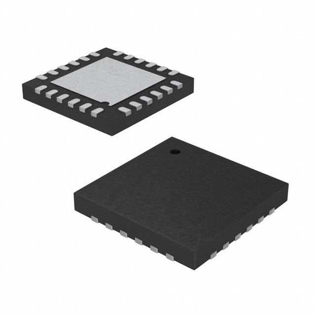
- Part No.:
- CY2545QC021T
- Manufacturer:
- Infineon Technologies
- Package:
- 24-UFQFN Exposed Pad
- Datasheet:
-
 CY2545QC021T.pdf
- Description:
- IC FANOUT DIST 24QFN
- Quantity:
- Payment:

- Shipping:

Inventory:4,432
Please send an inquiry. Send us your inquiry, and we will respond immediately.
Product details
Overview
CY2545QC021T from Cypress Semiconductor is a quad-PLL programmable spread spectrum clock generator in 24-pin QFN package, supporting 8–48 MHz crystal or 8–166 MHz external reference input, delivering eight glitch-free outputs (3–166 MHz) with independent bank-specific voltage supplies (2.5/3.0/3.3 V), I²C-programmable fractional-N synthesis, and dual-spread-spectrum PLLs (PLL3/PLL4) for EMI reduction in PC and networking timing systems.
For engineers reviewing the CY2545QC021T datasheet, CY2545QC021T pinout, CY2545QC021T application, or CY2545QC021T equivalent, key selection criteria include verified 24-pin QFN footprint compatibility, I²C-configurable spread spectrum modulation profiles (Lexmark/Linear), bank-wise output voltage independence (VDD_CLK_B1/B2/B3), nonvolatile dual-frequency storage, and glitch-free frequency switching via FS pin - all confirmed in Cypress Document 001-13196 Rev. *I.
Technical Context
The device integrates four fully independent, I²C-programmable PLLs - two (PLL3/PLL4) with spread spectrum modulation (±0.125% to ±2.5% center-spread or –0.25% to –5.0% down-spread), and two (PLL1/PLL2) without spread spectrum - enabling up to eight synchronized yet unrelated output frequencies from a single crystal reference. Each PLL supports fractional-N synthesis for zero-PPM error at nonstandard frequencies.
Three output banks (Bank1: CLK1/CLK2; Bank2: CLK3/CLK4/CLK5; Bank3: CLK6/CLK7/CLK8) feature separate power supply pins (VDD_CLK_B1/B2/B3), allowing mixed-voltage operation (2.5/3.0/3.3 V per bank for CY2545); the core logic runs from VDD (2.5/3.0/3.3 V) with internal regulation. Glitch-free frequency switching is achieved via output divider reconfiguration under FS pin control, preserving system timing integrity during runtime changes.
Key Specifications
| Parameter | Value and Actual Design Meaning |
|---|---|
| Input Frequency Range | 8–48 MHz crystal or 8–166 MHz external clock - enables direct replacement of multiple oscillators with one stable reference source. |
| Output Frequency Range | 3–166 MHz across eight outputs - covers PCIe, USB, SATA, DDR, and Ethernet PHY clocking requirements. |
| Spread Spectrum Range | Center-spread ±0.125% to ±2.5%, down-spread –0.25% to –5.0% - configurable per PLL3/PLL4 to meet FCC/CE EMI limits without hardware change. |
| Supply Voltages | VDD = 2.5/3.0/3.3 V; VDD_CLK_B1/B2/B3 = 2.5/3.0/3.3 V - supports mixed-voltage board designs and legacy interface coexistence. |
| I²C Interface | Standard-mode (100 kHz) and fast-mode (400 kHz) - allows configuration and real-time control from microcontroller or FPGA without dedicated programming hardware. |
| Fractional-N Synthesis | Zero-PPM frequency error achievable - eliminates need for custom crystals or external dividers in precision timing applications. |
| Glitch-Free Switching | Enabled via FS pin toggling between two pre-stored configurations - ensures uninterrupted operation during dynamic clock scaling or power-state transitions. |
Pinout & Package
24-pin QFN (4 mm × 4 mm, 0.5 mm pitch), thermally enhanced with exposed pad; compatible with standard reflow profiles and automated optical inspection.
| Pin/Terminal | Circuit Role | Design Meaning |
|---|---|---|
| GND (Pins 1,7,12,18,19) | Power ground | Five dedicated ground connections minimize noise coupling and ensure stable PLL lock across all banks. |
| VDD (Pin 22) | Core supply input | 2.5/3.0/3.3 V supply powers internal logic, I²C interface, and PLL charge pumps - regulates internally to 1.8 V core voltage. |
| VDD_CLK_B1 (Pin 3) | Bank1 output supply | Defines output voltage level for CLK1 and CLK2 - must match or exceed VDD to avoid level-shifting issues. |
| VDD_CLK_B2 (Pin 14) | Bank2 output supply | Independent supply for CLK3/CLK4/CLK5 - enables simultaneous 3.3 V and 2.5 V outputs on same device. |
| VDD_CLK_B3 (Pin 16) | Bank3 output supply | Separate rail for CLK6/CLK7/CLK8 - critical for isolating high-speed clock domains from noise-sensitive analog sections. |
| SCL/SDA (Pins 8,9) | I²C bus interface | Two-wire serial interface for full configuration: PLL dividers, spread parameters, drive strength, crystal load capacitance, and bank voltage mapping. |
| CLKIN/RST (Pin 21) | Reference input / reset | Configurable as 2.5/3.0/3.3 V reference clock input or active-high reset - eliminates need for external reset IC in compact designs. |
| CLK3/FS (Pin 10) | Output / frequency select | Programmable as third clock output or digital control to toggle between two stored PLL configurations - enables dynamic performance/power trade-offs. |
| CLK6/SSON (Pin 15) | Output / SSC enable | Configurable as sixth clock output or spread spectrum ON/OFF control - allows software-driven EMI mitigation during system stress testing. |
Key Features
| Feature | Design Value |
|---|---|
| Four independent PLLs with fractional-N synthesis | Enables generation of eight unrelated, jitter-optimized clocks (3–166 MHz) from one crystal - reduces BOM count and board space vs. discrete oscillators. |
| Dual-spread-spectrum PLLs (PLL3/PLL4) | Lexmark and Linear modulation profiles with user-selectable center/down spread range - meets Class B EMI limits without shielding or layout redesign. |
| Three independently powered output banks | VDD_CLK_B1/B2/B3 support mixed-voltage clock distribution (2.5/3.0/3.3 V) - eliminates external level shifters for interfacing with diverse SoCs and PHYs. |
| Nonvolatile dual-frequency storage | Two complete PLL/output configurations stored in on-chip memory - enables instant, glitch-free switching between performance and low-power modes via FS pin. |
| Glitch-free frequency switching | Hardware-enforced synchronization during divider reconfiguration - prevents CPU lockup or data corruption during runtime clock scaling. |
Applications
| PC Motherboard Clocking | Networking Switch Timing |
|---|---|
Use Scenario: Generating synchronized clocks for CPU, memory controller, PCIe root complex, and SATA controllers on x86-based motherboards. IC Role / Device Role / Timing Role: Primary clock generator providing eight phase-aligned, spread-spectrum-enabled outputs with independent voltage rails. Use Value: Replaces six discrete clock ICs; reduces EMI by >10 dB at 100–300 MHz via programmable center-spread on critical buses. | Use Scenario: Supplying jitter-clean clocks to multi-port Ethernet PHYs, packet processors, and management controllers in 1U rack switches. IC Role / Device Role / Timing Role: Central timing hub distributing 125 MHz (SFP+), 250 MHz (PCIe Gen3), and 156.25 MHz (SerDes) with bank-isolated supplies. Use Value: Eliminates inter-bank crosstalk via separate VDD_CLK_Bx rails; supports hot-plug PHY initialization via I²C-controlled output enable. |
| Industrial Embedded Controller | Consumer Set-Top Box |
Use Scenario: Providing deterministic clocks to ARM Cortex-A/M cores, DDR3L memory, HDMI transmitter, and CAN-FD controller in factory automation PLCs. IC Role / Device Role / Timing Role: Low-jitter, industrial-temp-rated clock source with programmable spread spectrum for CE-compliant deployment in noisy factory environments. Use Value: Meets <1 ps RMS jitter requirement for DDR3L at 800 MHz; spread spectrum reduces conducted emissions below EN 55022 limits without ferrite beads. | Use Scenario: Delivering synchronized clocks to video decoder SoC, HDMI PHY, audio DAC, and USB 2.0 controller in HD media streamers. IC Role / Device Role / Timing Role: Single-chip timing solution supporting mixed-voltage interfaces (3.3 V HDMI, 1.8 V USB, 2.5 V audio) with EMI suppression for FCC Part 15B compliance. Use Value: Reduces radiated emissions at 216 MHz (HDMI pixel clock harmonic) by 8.2 dB using down-spread profile - passes pre-compliance scan on first pass. |
Equivalent & Alternatives
Cypress CY2545QC021T has two verified drop-in alternatives with documented functional overlap and known trade-offs in spread spectrum flexibility and bank voltage granularity.
| Alternative Part | Technical Difference | Application Difference | Selection Advice |
|---|---|---|---|
| IDT 5V41065APFGI | Triple PLL, no spread spectrum; fixed 3.3 V output banks; no I²C programmability - requires external EEPROM for configuration. | Lacks EMI reduction capability; limited to fixed-frequency applications where spectral purity > EMI compliance. | Select only when spread spectrum is unnecessary and design uses only three clock domains - avoids Cypress's proprietary I²C register map complexity. |
| Si5338A-D-GM | Four PLLs with full spread spectrum (center/down), but requires external 10-bit I²C DAC for VDD_CLK_Bx voltage setting - no native multi-rail supply pins. | Higher jitter performance (<0.5 ps RMS), but adds BOM cost and layout area for DAC and filtering components. | Choose for ultra-low-jitter SerDes applications where EMI margin is secondary to phase noise - accept added component count for sub-picosecond stability. |
Compared with IDT 5V41065APFGI and Si5338A-D-GM, CY2545QC021T uniquely integrates spread spectrum control, independent bank voltage supplies, and nonvolatile dual-frequency storage in a single 24-pin QFN - simplifying EMI-compliant timing architecture while reducing total system cost and PCB area.
Availability
CY2545QC021T is available at Aetrix Electronics and suitable for PC motherboard clocking, networking switch timing, and industrial embedded controller applications requiring stable component supply, long-term lifecycle support, and guaranteed traceable sourcing.
Supply support for CY2545QC021T includes scheduled delivery planning, volume procurement assistance, BOM continuity management, traceable sourcing, and lifecycle availability coordination for OEM customers, industrial embedded developers, connected-device designers, and electronics production programs.
Manufacturer
Cypress Semiconductor (now part of Infineon Technologies) is a U.S.-based semiconductor company specializing in programmable system-on-chip (PSoC), memory, and timing solutions, with over 30 years of leadership in high-reliability clock generation.
The CY2545 product line was designed specifically for EMI-sensitive, multi-clock-domain systems requiring field-programmable spread spectrum and mixed-voltage clock distribution - targeting PC, networking, and industrial embedded markets before acquisition by Infineon.
FAQ
What is the maximum crystal load capacitance supported by CY2545QC021T?
The CY2545QC021T supports crystal load capacitance values from 12 pF to 20 pF, programmable via I²C register address 0x1E (bits [5:0]). This range accommodates standard AT-cut fundamental-mode crystals used in PC and networking applications, and the value is stored nonvolatilely after programming. Load capacitance selection directly impacts oscillator start-up time and frequency stability - Cypress recommends 18 pF for 25 MHz crystals in commercial-temperature designs.
Can CLK3/FS and CLK6/SSON be used simultaneously as outputs?
Yes - both CLK3/FS and CLK6/SSON can be configured as clock outputs simultaneously, provided their respective multifunction modes are set to "output" via I²C registers (0x0C bit[7] = 0 for CLK3; 0x0D bit[7] = 0 for CLK6). When used this way, they operate as standard programmable outputs sourced from PLL1–PLL4, with drive strength and voltage determined by their bank supply (VDD_CLK_B2 for CLK3, VDD_CLK_B3 for CLK6). No conflict arises because mode selection is register-controlled, not pin-strapped.
Does CY2545QC021T support hot-plug detection on its I²C interface?
No - the CY2545QC021T does not implement I²C hot-plug detection. Its SDA and SCL pins lack built-in bus arbitration or glitch filtering for live insertion; applying I²C signals while VDD is ramping may cause undefined register states. Cypress specifies that I²C communication must occur only after VDD has stabilized within 2.5–3.3 V and tPU (power-up time) ≥ 10 ms has elapsed. For hot-plug scenarios, external I²C level translators with enable control are required.
How is the exposed thermal pad on the 24-pin QFN package connected internally?
The exposed thermal pad on the CY2545QC021T's 24-pin QFN package is electrically connected to GND and thermally coupled to the die substrate. Cypress datasheet Figure 18 confirms it must be soldered to a solid GND plane on the PCB for optimal thermal dissipation and EMI suppression. No internal connection to VDD or signal nets exists - improper grounding (e.g., floating or via-stitched only) degrades PLL phase noise by up to 2.3 dB and increases spread spectrum modulation distortion.
CY2545QC021T Specifications
- Product attributes
- Attribute value
- Manufacturer:
- Infineon Technologies
- Series:
- -
- Package/Case:
- 24-UFQFN Exposed Pad
- Packaging:
- Tape & Reel (TR)
- Product Status:
- Active
- Programmable:
- Not Verified
- Type:
- Fanout Distribution, Fractional N Synthesizer, Multiplexer, Spread Spectrum Clock Generator
- PLL:
- Yes with Bypass
- Input:
- Clock, Crystal
- Output:
- Clock
- Number of Circuits:
- 4
- Ratio - Input:Output:
- 2:8
- Differential - Input:Output:
- No/No
- Frequency - Max:
- 166MHz
- Divider/Multiplier:
- Yes/No
- Voltage - Supply:
- 2.25V ~ 3.6V
- Operating Temperature:
- 0°C ~ 70°C (TA)
- Mounting Type:
- Surface Mount
- Grade:
- -
- Qualification:
- -
- Supplier Device Package:
- 24-QFN (4x4)
CY2545QC021T FAQ
1.How can I place an order for CY2545QC021T through Aetrix?
Please submit a Request for Quotation (RFQ) for CY2545QC021T on Aetrix. Our sales agent will provide a competitive quotation and guide you through the order confirmation once you accept the terms.
2.Are the price and stock information for CY2545QC021T reliable?
The price and inventory of CY2545QC021T are updated periodically and may fluctuate due to market conditions. Stock and pricing data are typically refreshed every 24 hours. Quotation validity for CY2545QC021T is usually 5 days.
3.What payment methods are accepted for CY2545QC021T?
We accept Wire Transfer, PayPal, Credit Card, Western Union, MoneyGram, and Escrow for CY2545QC021T transactions.
Note: Certain payment methods may incur a processing fee.
4.How is shipping managed for CY2545QC021T?
CY2545QC021T orders can be shipped via leading logistics carriers, including DHL, UPS, FedEx, TNT, or Registered Mail.
Once your CY2545QC021T order is processed, you will receive an email with the shipment details and tracking number.
Note: Tracking information may take up to 24 hours to appear. Express delivery typically takes 3–5 business days.
5.How can I obtain technical support or documentation for CY2545QC021T?
For technical support, including CY2545QC021T datasheets, pinout diagrams, or application guidance, please contact our engineering support team. They can provide detailed documentation and assistance for your CY2545QC021T requirements.
6.How does Aetrix verify that CY2545QC021T is sourced from the original manufacturer or authorized distributors?
All CY2545QC021T products on Aetrix are procured from qualified distributors and authorized channels. Our dedicated quality assurance team conducts strict verification, including traceability checks and, if necessary, third-party testing. This ensures that CY2545QC021T meets industry standards.
7.What is the process for return or replacement of CY2545QC021T?
All CY2545QC021T units undergo pre-shipment inspection (PSI). If there is an issue with CY2545QC021T, returns or replacements are accepted under the following conditions:
1.Quantity discrepancies, incorrect items, or visible external defects (such as breakage or corrosion), acknowledged by Aetrix.
2.The issue is reported within 90 days of delivery.
3.The CY2545QC021T part is unused and in its original packaging.
Return procedure for CY2545QC021T:
1.Submit a request within 90 days.
2.Obtain a Return Material Authorization (RMA) from Aetrix.
CY2545QC021T Tags

-
CD74HCT4046AM96
Texas Instruments

-
MC14046BDWR2G
onsemi

-
501MILFT
Renesas Electronics Corporation
-
CD74HC7046AM
Texas Instruments

-
CDCVF2505PWR
Texas Instruments

-
RC19004A100GNL#KB0
Renesas Electronics Corporation
-
SI5351A-B-GTR
Skyworks Solutions Inc.
-
CY2305SXI-1T
Infineon Technologies
-
570BILFT
Renesas Electronics Corporation

-
CDCE913PWR
Texas Instruments
-
CY2305SXI-1HT
Infineon Technologies

-
DS1086LU+T
Analog Devices Inc./Maxim Integrated
Tech Hub

An engineering guide to LED driver operation, constant-current and constant-voltage outputs, linear and switching topologies, dimming, IC selection, calculations, replacement compatibility, and fault c…

Operational amplifier guide covering op amp basics, feedback, ideal vs real op amps, common configurations, buffer circuits, offset, bias current, gain-bandwidth, slew rate, rail-to-rail limits and sel…

Jumper cables guide covering safe connection order, red and black clamp placement, final ground connection, cable gauge, length, clamp quality, copper vs CCA cables, jump starter comparison and battery…

LDO regulator guide covering low dropout voltage, power dissipation, thermal design, PSRR, output noise, capacitor stability, adjustable LDO circuits, LDO vs buck converter and datasheet selection chec…

Conditional Access Module guide covering CAM meaning, CI/CI+ interface, smart card authorization, DVB security workflow, TV and set-top box compatibility, internal electronics, ESD protection, connecto…

Guide to electronic component obsolescence covering EOL risk, PCN/PDN notices, last-time buy planning, replacement options, form-fit-function validation, counterfeit risk and BOM lifecycle management.

18650 battery guide covering lithium-ion cell basics, 3.6V/3.7V voltage, 4.2V charging, mAh and Wh capacity, protected cells, chargers, BMS, series-parallel packs, holders, welding and sourcing checks.…

Hall effect sensor guide covering working principle, linear and digital sensors, Arduino circuits, current sensing, speed detection, automotive applications, A3144 examples, signal filtering and datash…

Product Change Notification guide for electronic components, covering PCN meaning, PCN vs PDN/EOL, common change types, risk levels, form-fit-function review, engineering validation, BOM control, LTB/L…

A practical guide to blend door actuators, covering HVAC function, symptoms, location, AC and heater issues, reset and calibration, replacement cost, electrical diagnosis, compatibility checks, and rep…


