
 My Inquiry
 My Account


Skyworks Solutions Inc. CY28317PVXC-2
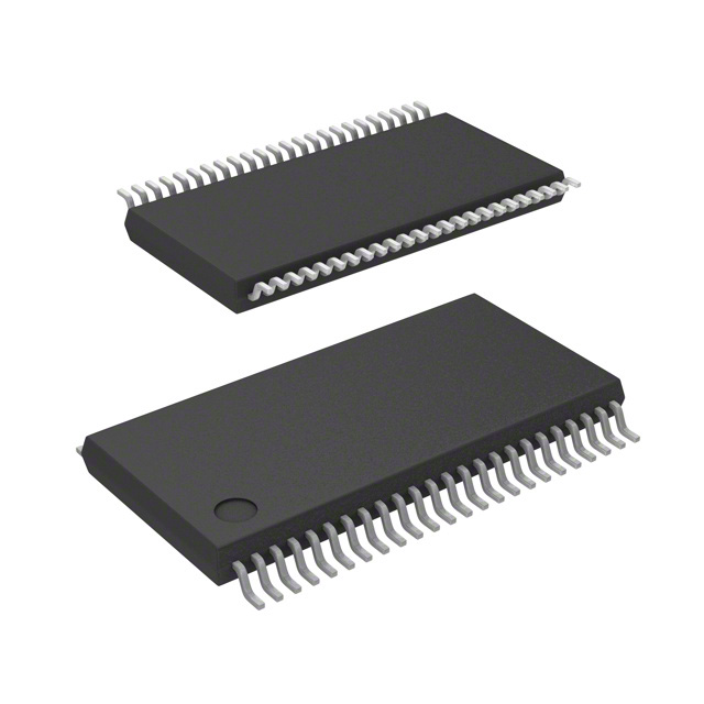
- Part No.:
- CY28317PVXC-2
- Manufacturer:
- Skyworks Solutions Inc.
- Category:
- Application Specific Clock/Timing
- Package:
- 48-BSSOP (0.295", 7.50mm Width)
- Datasheet:
-
 CY28317PVXC-2.pdf
- Description:
- IC CLK FTG VIA PL/E133T 48SSOP
- Quantity:
- Payment:

- Shipping:

Inventory:2,285
Please send an inquiry. Send us your inquiry, and we will respond immediately.
Product details
Overview
CY28317PVXC-2 from Silicon Labs is a single-chip system frequency synthesizer designed specifically for VIA PL133T and PLE133T mobile chipsets. It delivers programmable CPU clock outputs from 50 MHz to 248 MHz in <1 MHz increments, supports SMBus-configurable PCI/SDRAM clocks with programmable drive strength and output skew, and integrates a fail-safe watchdog timer with automatic recovery frequency switching. It is used in legacy x86 mobile platform timing subsystems requiring robust clock management and system-level fault recovery.
For engineers reviewing the CY28317PVXC-2 datasheet, CY28317PVXC-2 pinout, CY28317PVXC-2 application, or CY28317PVXC-2 equivalent, key selection considerations include its 48-pin TSSOP package, SMBus-programmable CPU/PCI/SDRAM clock outputs, integrated watchdog timer with recovery frequency mode, spread-spectrum EMI suppression, and hardware/firmware-controlled clock stop and reset generation.
Technical Context
The CY28317PVXC-2 implements dual PLL architecture: one dedicated to CPU clock synthesis (50–248 MHz) with programmable N/M dividers and gear constant selection, and another for PCI/SDRAM/48 MHz outputs derived from fixed-ratio division. Its SMBus interface supports byte/block read/write operations for full register configuration including watchdog timeout scaling (150 ms or 2.5 s prescaler), recovery frequency source selection (latched FS[4:0] or custom N/M values), and output enable/control bits.
It features hardware strapping via FS0–FS4 pins for power-on frequency selection, open-drain RST# assertion on watchdog timeout or frequency change, and differential CPU clock outputs (CPUT/CPUC) with selectable 0.7 V or 1.0 V swing via MULT_SEL and IREF. All outputs support programmable skew-CPU-to-CPU skew ≤175 ps, PCI-to-PCI skew ≤500 ps-and drive strength control per domain (CPU, PCI, SDRAM).
Key Specifications
| Parameter | Value and Actual Design Meaning |
|---|---|
| CPU Output Frequency Range | 50 MHz to 248 MHz, programmable in <1 MHz steps via SMBus N/M registers or FS[4:0] straps |
| CPU-to-CPU Output Skew | ≤175 ps, enabling tight timing alignment across dual CPU clock domains |
| PCI-to-PCI Output Skew | ≤500 ps, ensuring synchronous operation across multi-slot PCI bus segments |
| Watchdog Timer Range | 150 ms to 80 s, selectable via 150 ms or 2.5 s prescaler and 5-bit timeout counter |
| SMBus Interface | Supports byte read/write, word read/write, and block read/write protocols per SMBus 2.0 spec |
| Spread Spectrum | Configurable ±0.25%, ±0.5%, or –0.5% modulation depth for EMI reduction |
| Output Drive Strength | Programmable normal/high drive per group: CPU0:1, PCI, SDRAM, 48MHz, 24_48MHz |
Pinout & Package
Package: 48-pin TSSOP (lead-free, RoHS-compliant), 7.0 mm × 12.0 mm body, 0.5 mm pitch.
| Pin/Terminal | Circuit Role | Design Meaning |
|---|---|---|
| CPU0, CPU1 (Pins 48, 47) | Single-ended CPU clock outputs | 3.3 V LVTTL-compatible clocks for processor and chipset; individually enable/disable via SMBus register |
| CPUT, CPUC (Pins 44, 43) | Differential CPU clock outputs | LVDS-like differential pair with 0.7 V or 1.0 V swing selected by MULT_SEL and IREF current reference |
| PCI2:6 (Pins 13–17) | PCI clock outputs | Five 3.3 V, 33 MHz PCI clocks; each independently controllable via SMBus register bit |
| SDRAM0:6 (Pins 30, 31, 33, 34, 36, 37, 39) | SDRAM clock outputs | Seven buffered copies of SDRAMIN signal; all active high, 3.3 V, individually maskable |
| RST# (Pin 41) | System reset output | Open-drain output asserted low on watchdog timeout or frequency-change event when enabled |
| SCLK, SDATA (Pins 25, 24) | SMBus interface | Two-wire serial bus compliant with SMBus 2.0; supports block transfers for efficient register programming |
| VTT_PWRGD# (Pin 4) | Power-good input | 3.3 V LVTTL input that latches FS[4:0] strap values and enables all clock outputs after power stabilization |
Key Features
| Feature | Design Value |
|---|---|
| Fail-safe watchdog timer with recovery mode | Locks device into preconfigured recovery frequency and asserts RST# on timeout; SMBus access disabled until WD_EN cleared |
| Hardware/firmware frequency selection | FS[4:0] pins set boot frequency; SMBus registers allow dynamic reprogramming of CPU output (50–248 MHz) without reset |
| Per-domain output skew control | CPU outputs adjustable in ±150/±300/±450/±600 ps steps; PCI outputs adjustable in ±500 ps steps |
| Multi-voltage domain power supply | VDD_CPU_2.5 (2.5 V) for differential CPU outputs; VDD_REF/VDD_PCI/VDD_SDRAM/VDD_48MHz (3.3 V) for logic and other outputs |
| EMI suppression via spread spectrum | Configurable modulation depth (±0.25%, ±0.5%, –0.5%) and enable/disable control per output group |
Applications
| Mobile x86 Platform Timing | VIA Chipset-Based Embedded Systems |
|---|---|
Use Scenario: Legacy notebook or tablet designs using VIA PL133T/PLE133T chipsets requiring precise, configurable clock distribution. IC Role / Device Role / Timing Role: Primary system clock synthesizer generating CPU, PCI, and SDRAM clocks from a single 14.318 MHz crystal. Use Value: Eliminates discrete clock generator + buffer combinations; reduces BOM count and layout complexity while enabling BIOS-driven frequency tuning. |
Use Scenario: Industrial or medical embedded systems built on VIA-based motherboards needing reliable clock fault recovery. IC Role / Device Role / Timing Role: Fault-tolerant timing controller providing watchdog-triggered fallback to known-good CPU frequency and system reset. Use Value: Enables unattended system recovery from BIOS hangs or unstable overclocking attempts without manual intervention. |
| PCI Bus Synchronization | SDRAM Clock Buffering |
Use Scenario: Multi-slot PCI expansion chassis where inter-slot clock skew must be minimized. IC Role / Device Role / Timing Role: Low-skew PCI clock distributor with five independent 33 MHz outputs and per-output enable control. Use Value: Achieves ≤500 ps PCI-to-PCI skew across all slots, meeting PCI specification setup/hold margin requirements. |
Use Scenario: Systems with multiple SDRAM banks requiring phase-aligned clock delivery. IC Role / Device Role / Timing Role: Seven-output SDRAM clock buffer replicating a single SDRAMIN reference with matched trace delay. Use Value: Provides seven identical, low-jitter SDRAM clocks with guaranteed ≤175 ps skew between CPU outputs driving same memory controller. |
Equivalent & Alternatives
The following parts are listed as comparable options for similar clock synthesizer applications.
| Alternative Part | Technical Difference | Application Difference | Selection Advice |
|---|---|---|---|
| CY28316PVXC | No integrated watchdog timer; lacks recovery frequency mode and RST# generation on timeout | Suitable only for non-fault-critical platforms where BIOS handles all recovery | Select CY28317PVXC-2 when watchdog-triggered system reset and automatic frequency fallback are required. |
| ICS9LPRS355AKLFT | Supports DDR2/DDR3 memory clocks; includes PCIe reference clock outputs; no differential CPU outputs | Targeted at newer Intel/AMD platforms with DDR2/3 and PCIe; incompatible with VIA PL133T timing architecture | Choose CY28317PVXC-2 for strict VIA PL133T/PLE133T compatibility and differential CPU clock support. |
Compared with CY28316PVXC and ICS9LPRS355AKLFT, the CY28317PVXC-2 uniquely combines VIA-specific frequency ratios, integrated watchdog with hardware-enforced recovery mode, and dual-mode (single-ended + differential) CPU clock outputs - making it irreplaceable in validated PL133T/PLE133T mobile designs requiring fault resilience.
Availability
CY28317PVXC-2 is available at Aetrix Electronics and suitable for mobile computing platforms, VIA chipset-based industrial controllers, and legacy embedded systems requiring stable component supply and long-term lifecycle support.
Supply support for CY28317PVXC-2 includes scheduled delivery planning, volume procurement assistance, BOM continuity management, traceable sourcing, and lifecycle availability coordination for OEM customers, industrial embedded developers, connected-device designers, and electronics production programs.
Manufacturer
Silicon Labs is a fabless semiconductor company specializing in timing, wireless, and sensor solutions, with deep expertise in clock generation and jitter performance.
The CY28317PVXC-2 belongs to Silicon Labs' legacy clock synthesizer product line, engineered specifically for VIA Technologies' PL133T and PLE133T mobile chipsets to deliver integrated, configurable, and fault-resilient system timing.
FAQ
What is the primary function of the CY28317PVXC-2 in a VIA PL133T-based system?
The CY28317PVXC-2 serves as the central system clock synthesizer, generating synchronized CPU, PCI, and SDRAM clocks from a 14.318 MHz crystal. It enables BIOS-configurable CPU frequencies (50–248 MHz), provides hardware-strapped or SMBus-programmed output control, and ensures timing compliance across all VIA PL133T-dependent subsystems. Its design directly maps to the PL133T's clocking architecture, making CY28317PVXC-2 essential for functional timing in these platforms.
Does the CY28317PVXC-2 support differential CPU clock outputs, and how are they configured?
Yes, the CY28317PVXC-2 provides differential CPU clock outputs CPUT and CPUC (Pins 44 and 43). Their output swing is controlled by MULT_SEL (Pin 22) and IREF (Pin 40): MULT_SEL = LOW yields 1.0 V swing; MULT_SEL = HIGH yields 0.7 V swing. The IREF pin sets the reference current (5.00 mA or 2.32 mA) per Table 1, directly determining drive strength and termination matching for differential signaling integrity.
How does the watchdog timer in the CY28317PVXC-2 operate during a system hang?
When enabled (WD_EN = 1), the CY28317PVXC-2 watchdog timer starts counting down after any CPU frequency change. On timeout, it asserts RST# (Pin 41), reloads a preconfigured recovery frequency (from latched FS[4:0] or custom N/M registers), and locks itself into recovery mode - disabling further SMBus frequency updates until WD_EN is cleared by system software. This ensures deterministic fallback without external supervision.
Can the CY28317PVXC-2 generate non-standard PCI clock frequencies, and what limits apply?
No - the CY28317PVXC-2 generates only standard 33 MHz PCI clocks on PCI0_F/FS4, PCI1/FS3, and PCI2:6 outputs. Its internal PLL and divider architecture is fixed for PCI compliance; frequency selection affects only CPU, SDRAM, and 48/24 MHz outputs. PCI outputs derive from a fixed ratio of the main PLL, and their enable/disable state is controlled per-pin via SMBus register bits, but their 33 MHz frequency is immutable.
What package and lead finish does the CY28317PVXC-2 use, and is it RoHS-compliant?
The CY28317PVXC-2 is supplied in a 48-pin TSSOP package (7.0 mm × 12.0 mm, 0.5 mm pitch) with lead-free (Pb-free) matte tin finish, fully compliant with RoHS Directive 2011/65/EU and JEDEC J-STD-020 moisture sensitivity level 3 (MSL3). The "-2" suffix denotes the commercial temperature grade (0 °C to +70 °C), and "PVXC" confirms the TSSOP packaging and Pb-free construction.
CY28317PVXC-2 Specifications
- Product attributes
- Attribute value
- Manufacturer:
- Skyworks Solutions Inc.
- Series:
- -
- Package/Case:
- 48-BSSOP (0.295", 7.50mm Width)
- Packaging:
- Tube
- Product Status:
- Obsolete
- Programmable:
- Not Verified
- PLL:
- Yes
- Main Purpose:
- -
- Input:
- Crystal
- Output:
- HCSL, LVCMOS
- Number of Circuits:
- 1
- Ratio - Input:Output:
- 1:20
- Differential - Input:Output:
- No/Yes
- Frequency - Max:
- 248MHz
- Voltage - Supply:
- 3.135V ~ 3.465V
- Operating Temperature:
- 0°C ~ 70°C
- Mounting Type:
- Surface Mount
- Grade:
- -
- Qualification:
- -
- Supplier Device Package:
- 48-SSOP
CY28317PVXC-2 FAQ
1.How can I place an order for CY28317PVXC-2 through Aetrix?
Please submit a Request for Quotation (RFQ) for CY28317PVXC-2 on Aetrix. Our sales agent will provide a competitive quotation and guide you through the order confirmation once you accept the terms.
2.Are the price and stock information for CY28317PVXC-2 reliable?
The price and inventory of CY28317PVXC-2 are updated periodically and may fluctuate due to market conditions. Stock and pricing data are typically refreshed every 24 hours. Quotation validity for CY28317PVXC-2 is usually 5 days.
3.What payment methods are accepted for CY28317PVXC-2?
We accept Wire Transfer, PayPal, Credit Card, Western Union, MoneyGram, and Escrow for CY28317PVXC-2 transactions.
Note: Certain payment methods may incur a processing fee.
4.How is shipping managed for CY28317PVXC-2?
CY28317PVXC-2 orders can be shipped via leading logistics carriers, including DHL, UPS, FedEx, TNT, or Registered Mail.
Once your CY28317PVXC-2 order is processed, you will receive an email with the shipment details and tracking number.
Note: Tracking information may take up to 24 hours to appear. Express delivery typically takes 3–5 business days.
5.How can I obtain technical support or documentation for CY28317PVXC-2?
For technical support, including CY28317PVXC-2 datasheets, pinout diagrams, or application guidance, please contact our engineering support team. They can provide detailed documentation and assistance for your CY28317PVXC-2 requirements.
6.How does Aetrix verify that CY28317PVXC-2 is sourced from the original manufacturer or authorized distributors?
All CY28317PVXC-2 products on Aetrix are procured from qualified distributors and authorized channels. Our dedicated quality assurance team conducts strict verification, including traceability checks and, if necessary, third-party testing. This ensures that CY28317PVXC-2 meets industry standards.
7.What is the process for return or replacement of CY28317PVXC-2?
All CY28317PVXC-2 units undergo pre-shipment inspection (PSI). If there is an issue with CY28317PVXC-2, returns or replacements are accepted under the following conditions:
1.Quantity discrepancies, incorrect items, or visible external defects (such as breakage or corrosion), acknowledged by Aetrix.
2.The issue is reported within 90 days of delivery.
3.The CY28317PVXC-2 part is unused and in its original packaging.
Return procedure for CY28317PVXC-2:
1.Submit a request within 90 days.
2.Obtain a Return Material Authorization (RMA) from Aetrix.
CY28317PVXC-2 Tags

-
LMK00334RTVRQ1
Texas Instruments
.jpg)
-
DSC557-0344FI0T
Microchip Technology

-
9FGV0241AKILFT
Renesas

-
9DBL0452CKILFT
Renesas
-
DSC557-0344FL1T
Microchip Technology

-
RC19008AGND#KB0
Renesas
-
RC19008AGND#BB0
Renesas

-
9DB403DGILFT
Renesas

-
9DB233AGILFT
Renesas

-
9DB803DGILFT
Renesas
-
9FGL0851DKILFT
Renesas

-
AB-557-03-HCHC-F-L-C-T
Abracon LLC
Tech Hub

Counterfeit components can hide behind convincing markings and passing basic function tests. This engineering reference covers source traceability, external inspection, X-ray, XRF, electrical testing, …

A practical engineering and sourcing framework covering lifecycle verification, lifetime-buy calculations, replacement qualification, supplier checks and counterfeit-risk controls.

TTL and CMOS logic families differ in thresholds, loading, output drive, power and timing. This engineering guide compares 74HC and 74HCT, calculates noise margins and checks 3.3 V/5 V compatibility.

A practical engineering guide to 3.3V and 5V logic compatibility, input thresholds, resistor dividers, translator ICs, MOSFET level shifting, I2C pull-ups, timing limits and power-sequencing risks.

The 74HC595 uses push-pull logic outputs, while the TPIC6B595 uses 50 V open-drain DMOS sinks for higher-power loads. This guide compares timing, current limits, 3.3 V interfacing, load wiring, thermal…

The 74HC595 converts serial data into eight stable parallel outputs. This guide covers pin functions, shift and storage timing, OE and MR behavior, drive-current limits, cascading, voltage compatibilit…

A technical comparison of level-sensitive latches and edge-triggered flip-flops, covering timing windows, setup and hold limits, master–slave operation, time borrowing, race-through, HDL inference and…

A D latch stores one bit while Enable controls when data can pass. This reference covers gate-level operation, truth tables, transparency, setup and hold timing, LE versus OE, common ICs and practical …

An SR latch stores one bit through cross-coupled feedback. This engineering reference covers NOR and NAND implementations, truth tables, forbidden-state recovery, gated operation, switch debouncing, fa…

Latch circuits retain one bit through feedback. This technical reference covers SR and D latches, truth tables, transparency, timing limits, latch-versus-flip-flop behavior, applications and common log…


