
 My Inquiry
 My Account


Skyworks Solutions Inc. CY28445LFXC-5T
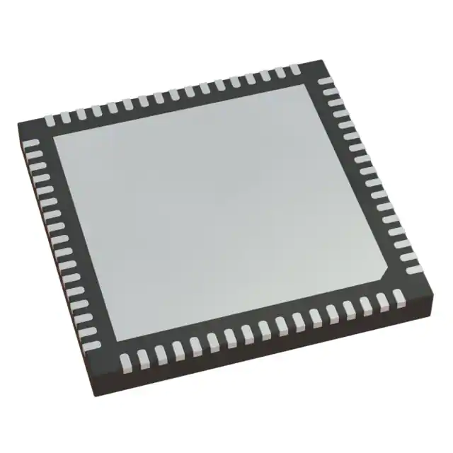
- Part No.:
- CY28445LFXC-5T
- Manufacturer:
- Skyworks Solutions Inc.
- Category:
- Application Specific Clock/Timing
- Package:
- 68-VFQFN Exposed Pad
- Datasheet:
-
 CY28445LFXC-5T.pdf
- Description:
- IC CLOCK CALISTOGA CK410M 68QFN
- Quantity:
- Payment:

- Shipping:

Inventory:3,357
Please send an inquiry. Send us your inquiry, and we will respond immediately.
Product details
Overview
CY28445LFXC-5T from Silicon Labs is a clock generator IC designed specifically for Intel® Calistoga chipset platforms, delivering 100 MHz differential SRC clocks, 96 MHz differential dot clock, 27 MHz spread/non-spread video clock, 48 MHz USB clock, and 33 MHz PCI clock - all from a single 14.318 MHz crystal reference. It integrates CPU PLL, SRC PLL, fixed PLLs, and I²C programmability for system-level timing control in mobile computing motherboards.
For engineers reviewing the CY28445LFXC-5T datasheet, CY28445LFXC-5T pinout, CY28445LFXC-5T application, or CY28445LFXC-5T equivalent, key selection criteria include Intel CK410M compliance, differential LVDS output capability, per-clock enable/disable via CLKREQ#, spread spectrum control for EMI reduction, and 68-pin QFN package compatibility with Calistoga reference designs.
Technical Context
The CY28445LFXC-5T implements three independent PLLs: a CPU PLL supporting 100/133/166/200 MHz selectable frequencies, an SRC PLL generating 100 MHz differential serial reference clocks, and a fixed PLL for 96 MHz dot clock and 27 MHz video clocks. All outputs are LVDS-compliant with configurable drive strength and stoppable behavior.
It features dual-mode frequency select logic (FSA/FSB/FSC) sampled at VTT_PWRGD# assertion, I²C interface with readback capability (slave address D2h), and register-controlled spread spectrum (–0.45% to ±0.95% peak-to-peak), enabling precise EMI mitigation without external components.
Key Specifications
| Parameter | Value and Actual Design Meaning |
|---|---|
| CPU Clock Output | 100/133/166/200 MHz differential LVDS; selected via FSA/FSB/FSC pins at power-up |
| SRC Clock Output | Eight 100 MHz differential LVDS outputs (SRCT[1:8]/SRCC[1:8]) + SRCT0/SRCC0 + SRCT10/SRCC10 |
| Video Clocks | 96 MHz differential dot clock (DOT96T/C) and 27 MHz single-ended non-spread/spread outputs |
| USB & PCI Clocks | 48 MHz USB clock (FSA/48M pin) and five 33 MHz PCI clocks (PCI[1:5], PCIF0/1) |
| Reference Input | 14.318 MHz parallel-resonant crystal (20 pF load, 35 ppm tolerance, 30 ppm stability) |
| Supply Voltage | 3.3 V across six dedicated power domains: VDD_CPU, VDD_SRC, VDD_PCI, VDD_REF, VDD48, VDDA |
| Interface | I²C-compatible SMBus interface (SCLK/SDATA) with byte/block read/write and slave address 0xD2 |
Pinout & Package
68-pin QFN (MLF) package, 9 mm × 9 mm × 0.85 mm body, exposed thermal pad, RoHS-compliant, moisture sensitivity level 3.
| Pin/Terminal | Circuit Role | Design Meaning |
|---|---|---|
| 1 (PCIF1) | 33 MHz PCI clock output | Single-ended, 3.3V LVTTL, enabled via Control Register 2 bit 0 |
| 6,7 (DOT96T/C, 27M_non/Spread) | Dual-function video clock outputs | Pins configured as 96 MHz differential or 27 MHz single-ended based on FCTSEL[1:0] at VTT_PWRGD# |
| 10,11 (SRCT0/SRCC0) | Primary 100 MHz differential SRC clock pair | LVDS outputs; selectable between 100MT_SST/100MC_SST or SRCT0/SRCC0 via FCTSEL[1:0] |
| 36,37 (CPUT2_ITP/SRCT10) | Selectable CPU or SRC clock output | Default = SRCT10; ITP_SEL = 1 enables CPUT2_ITP mode |
| 47 (SCLK), 48 (SDATA) | I²C serial interface | SMBus-compatible clock/data lines; support register readback and dynamic clock enable/disable |
| 55 (CPU_STP#), 56 (PCI_STP#) | System stop request inputs | Active-low LVTTL inputs that gate CPU and PCI clocks synchronously without glitches |
| 59–60, 9,20,25,34,43 (CLKREQ#[1,3:6,8]) | Per-SRC clock enable inputs | Eight independent active-low inputs controlling SRC[T/C][0:10] stoppability via Control Registers 15–19 |
Key Features
| Feature | Design Value |
|---|---|
| Intel CK410M Compliance | Fully meets Intel® Calistoga chipset clock specification including timing margins, jitter, and voltage levels |
| Configurable Spread Spectrum | Programmable 16-step spread profile (–0.45% to ±0.95%) for EMI reduction without hardware changes |
| Differential LVDS Outputs | All CPU, SRC, and DOT96 clocks delivered as matched-pair LVDS signals minimizing skew and noise |
| Independent Clock Gating | Each of 11 SRC outputs can be individually stopped via dedicated CLKREQ# inputs or register control |
| Multi-Domain Power Management | Separate 3.3V supplies for CPU, SRC, PCI, REF, 48M, and analog PLL sections enable selective power-down |
| I²C Readback Capability | Full register visibility allows runtime verification of clock enable states, spread settings, and frequency selections |
Applications
| Mobile Notebook Motherboard | Embedded Industrial PC |
|---|---|
Use Scenario: Timing solution for Intel Calistoga-based laptop mainboards requiring CPU, SRC, PCI, USB, and display clocks. IC Role / Device Role / Timing Role: Primary clock synthesizer providing synchronized, low-jitter clocks to CPU, chipset, GPU, and peripheral controllers. Use Value: Eliminates need for multiple discrete oscillators and buffers; reduces BOM count by consolidating 14+ clock domains into one IC. | Use Scenario: Ruggedized embedded system using Calistoga platform in factory automation or medical imaging equipment. IC Role / Device Role / Timing Role: System clock hub managing power-aware clock gating for PCI peripherals and USB devices during sleep states. Use Value: Enables deep-sleep modes via CLKREQ# and PCI_STP# inputs while maintaining fast wake-up latency (<6 SRC cycles). |
| Digital Display Controller | USB 2.0 Host Interface |
Use Scenario: LCD/TFT panel timing controller requiring stable 96 MHz dot clock and 27 MHz video reference. IC Role / Device Role / Timing Role: Video clock source delivering both differential dot clock and spread/non-spread 27 MHz pixel clock. Use Value: Supports EMI-sensitive display interfaces with programmable spread spectrum on 27 MHz output without affecting 96 MHz timing integrity. | Use Scenario: USB 2.0 host controller needing precise 48 MHz clock with low phase noise for data transfer compliance. IC Role / Device Role / Timing Role: Dedicated 48 MHz clock generator with drive strength control (Control Register 8 bit 2) and glitch-free enable/disable. Use Value: Meets USB 2.0 full-speed timing requirements (±0.25% frequency accuracy) using internal PLL locked to crystal reference. |
Equivalent & Alternatives
The following parts are listed as comparable options for similar clock generator applications.
| Alternative Part | Technical Difference | Application Difference | Selection Advice |
|---|---|---|---|
| ICS9LPR503AGT | Supports Intel 945GME chipset; offers 100/125/133 MHz CPU outputs but lacks 96 MHz dot clock and 27 MHz dual-spread video outputs | Targeted at desktop/mobile platforms with different chipset timing requirements; no native Calistoga support | Choose only if migrating from Calistoga to 945GME architecture; requires PCB layout change due to 48-pin TSSOP vs. 68-pin QFN |
| Si5338A-C-GM | Programmable 4-output clock generator with fractional-N synthesis; supports arbitrary frequencies but no built-in Intel CK410M compliance or dedicated SRC/PCI pinouts | Used in custom timing designs where flexibility outweighs chipset-specific optimization; requires external configuration EEPROM | Prefer when multi-frequency agility or jitter performance < 0.5 ps RMS is required; not drop-in for Calistoga reference designs |
Compared with ICS9LPR503AGT and Si5338A-C-GM, the CY28445LFXC-5T delivers guaranteed CK410M compliance, integrated 96 MHz dot clock, and hardware-mapped CLKREQ# control - reducing firmware complexity and validation effort for Calistoga-based systems.
Availability
CY28445LFXC-5T is available at Aetrix Electronics and suitable for mobile notebook motherboard design, industrial embedded PC development, digital display controller integration, and USB 2.0 host interface timing applications requiring stable component supply and long-term lifecycle support.
Supply support for CY28445LFXC-5T includes scheduled delivery planning, volume procurement assistance, BOM continuity management, traceable sourcing, and lifecycle availability coordination for OEM customers, industrial embedded developers, connected-device designers, and electronics production programs.
Manufacturer
Silicon Labs is a fabless semiconductor company specializing in timing, wireless, and sensor solutions, with leadership in precision clock generation and low-power mixed-signal ICs.
The CY28445 product line was engineered to meet Intel's CK410M specification for Calistoga chipset platforms, delivering tightly integrated, low-jitter clock synthesis with minimal external components for mobile computing applications.
FAQ
What is the crystal requirement for CY28445LFXC-5T?
The CY28445LFXC-5T requires a 14.31818 MHz parallel-resonant AT-cut crystal with 20 pF load capacitance, maximum 35 ppm initial tolerance, and 30 ppm temperature stability. Using a series-resonant crystal causes up to 300 ppm frequency error and violates specification compliance. The CY28445LFXC-5T datasheet specifies trim capacitor calculation: Ce = 2 × CL − (Cs + Ci), where Cs is stray capacitance and Ci is internal pin capacitance.
How does CLKREQ# control work on CY28445LFXC-5T?
CLKREQ# inputs (CLKREQ#[1,3:6,8]) are active-low, debounced signals that gate individual SRC outputs. Each CLKREQ# pin controls specific SRC[T/C] pairs via Control Registers 15–19 - for example, CLKREQ#1 can be assigned to SRC[T/C]1 through register bit 0 of Control Register 19. Deassertion stops outputs after next transition; assertion resumes them within 2–6 SRC clock periods, glitch-free. The CY28445LFXC-5T supports up to eight independently controllable SRC outputs.
Is CY28445LFXC-5T pin-compatible with other CY28445 variants?
Yes, CY28445LFXC-5T shares identical 68-pin QFN footprint and pinout with CY28445-5 and CY28445LFXC-5, differing only in tape-and-reel packaging (LFXC) and temperature grade (-40°C to +85°C). All share identical electrical characteristics, register map, and timing behavior - making CY28445LFXC-5T a direct replacement in Calistoga reference designs requiring industrial temperature operation.
What spread spectrum options does CY28445LFXC-5T support?
The CY28445LFXC-5T supports 16 programmable spread spectrum profiles via Control Register 9 bits S[3:0], ranging from –0.45% to ±0.95% peak-to-peak modulation depth. Spread can be applied independently to CPU PLL (Control Register 8 bits 7–6), 27 MHz output (Control Register 9 bit 2), or LCD100M (Control Register 9 bit 1). The default setting is –0.45% down-spread, matching Lexmark's EMI reduction profile.
Does CY28445LFXC-5T support I²C readback of clock status?
Yes, CY28445LFXC-5T supports full I²C readback of all 20 control registers (0x00–0x13) via SMBus-compatible interface (SCLK/SDATA, slave address 0xD2). Engineers can verify real-time clock enable states (e.g., SRC[T/C]0 enabled via Register 0 bit 0), spread spectrum activation (Register 9 bit 1), or frequency select sampling results (Register 6 bits 2–0) - enabling closed-loop validation and debug without oscilloscope probing.
CY28445LFXC-5T Specifications
- Product attributes
- Attribute value
- Manufacturer:
- Skyworks Solutions Inc.
- Series:
- -
- Package/Case:
- 68-VFQFN Exposed Pad
- Packaging:
- Tape & Reel (TR)
- Product Status:
- Obsolete
- Programmable:
- Not Verified
- PLL:
- Yes
- Main Purpose:
- Intel CPU Servers
- Input:
- LVTTL, Crystal
- Output:
- HCSL, LVCMOS
- Number of Circuits:
- 1
- Ratio - Input:Output:
- 3:22
- Differential - Input:Output:
- No/Yes
- Frequency - Max:
- 200MHz
- Voltage - Supply:
- 3.135V ~ 3.465V
- Operating Temperature:
- 0°C ~ 85°C
- Mounting Type:
- Surface Mount
- Grade:
- -
- Qualification:
- -
- Supplier Device Package:
- 68-QFN (8x8)
CY28445LFXC-5T FAQ
1.How can I place an order for CY28445LFXC-5T through Aetrix?
Please submit a Request for Quotation (RFQ) for CY28445LFXC-5T on Aetrix. Our sales agent will provide a competitive quotation and guide you through the order confirmation once you accept the terms.
2.Are the price and stock information for CY28445LFXC-5T reliable?
The price and inventory of CY28445LFXC-5T are updated periodically and may fluctuate due to market conditions. Stock and pricing data are typically refreshed every 24 hours. Quotation validity for CY28445LFXC-5T is usually 5 days.
3.What payment methods are accepted for CY28445LFXC-5T?
We accept Wire Transfer, PayPal, Credit Card, Western Union, MoneyGram, and Escrow for CY28445LFXC-5T transactions.
Note: Certain payment methods may incur a processing fee.
4.How is shipping managed for CY28445LFXC-5T?
CY28445LFXC-5T orders can be shipped via leading logistics carriers, including DHL, UPS, FedEx, TNT, or Registered Mail.
Once your CY28445LFXC-5T order is processed, you will receive an email with the shipment details and tracking number.
Note: Tracking information may take up to 24 hours to appear. Express delivery typically takes 3–5 business days.
5.How can I obtain technical support or documentation for CY28445LFXC-5T?
For technical support, including CY28445LFXC-5T datasheets, pinout diagrams, or application guidance, please contact our engineering support team. They can provide detailed documentation and assistance for your CY28445LFXC-5T requirements.
6.How does Aetrix verify that CY28445LFXC-5T is sourced from the original manufacturer or authorized distributors?
All CY28445LFXC-5T products on Aetrix are procured from qualified distributors and authorized channels. Our dedicated quality assurance team conducts strict verification, including traceability checks and, if necessary, third-party testing. This ensures that CY28445LFXC-5T meets industry standards.
7.What is the process for return or replacement of CY28445LFXC-5T?
All CY28445LFXC-5T units undergo pre-shipment inspection (PSI). If there is an issue with CY28445LFXC-5T, returns or replacements are accepted under the following conditions:
1.Quantity discrepancies, incorrect items, or visible external defects (such as breakage or corrosion), acknowledged by Aetrix.
2.The issue is reported within 90 days of delivery.
3.The CY28445LFXC-5T part is unused and in its original packaging.
Return procedure for CY28445LFXC-5T:
1.Submit a request within 90 days.
2.Obtain a Return Material Authorization (RMA) from Aetrix.
CY28445LFXC-5T Tags

-
LMK00334RTVRQ1
Texas Instruments
.jpg)
-
DSC557-0344FI0T
Microchip Technology

-
9FGV0241AKILFT
Renesas

-
9DBL0452CKILFT
Renesas
-
DSC557-0344FL1T
Microchip Technology

-
RC19008AGND#KB0
Renesas
-
RC19008AGND#BB0
Renesas

-
9DB403DGILFT
Renesas

-
9DB233AGILFT
Renesas

-
9DB803DGILFT
Renesas
-
9FGL0851DKILFT
Renesas

-
AB-557-03-HCHC-F-L-C-T
Abracon LLC
Tech Hub

Counterfeit components can hide behind convincing markings and passing basic function tests. This engineering reference covers source traceability, external inspection, X-ray, XRF, electrical testing, …

A practical engineering and sourcing framework covering lifecycle verification, lifetime-buy calculations, replacement qualification, supplier checks and counterfeit-risk controls.

TTL and CMOS logic families differ in thresholds, loading, output drive, power and timing. This engineering guide compares 74HC and 74HCT, calculates noise margins and checks 3.3 V/5 V compatibility.

A practical engineering guide to 3.3V and 5V logic compatibility, input thresholds, resistor dividers, translator ICs, MOSFET level shifting, I2C pull-ups, timing limits and power-sequencing risks.

The 74HC595 uses push-pull logic outputs, while the TPIC6B595 uses 50 V open-drain DMOS sinks for higher-power loads. This guide compares timing, current limits, 3.3 V interfacing, load wiring, thermal…

The 74HC595 converts serial data into eight stable parallel outputs. This guide covers pin functions, shift and storage timing, OE and MR behavior, drive-current limits, cascading, voltage compatibilit…

A technical comparison of level-sensitive latches and edge-triggered flip-flops, covering timing windows, setup and hold limits, master–slave operation, time borrowing, race-through, HDL inference and…

A D latch stores one bit while Enable controls when data can pass. This reference covers gate-level operation, truth tables, transparency, setup and hold timing, LE versus OE, common ICs and practical …

An SR latch stores one bit through cross-coupled feedback. This engineering reference covers NOR and NAND implementations, truth tables, forbidden-state recovery, gated operation, switch debouncing, fa…

Latch circuits retain one bit through feedback. This technical reference covers SR and D latches, truth tables, transparency, timing limits, latch-versus-flip-flop behavior, applications and common log…


