
 My Inquiry
 My Account


Infineon Technologies CY7B994V-2BBIT
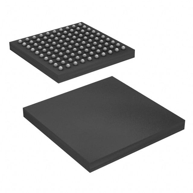
- Part No.:
- CY7B994V-2BBIT
- Manufacturer:
- Infineon Technologies
- Package:
- 100-LBGA
- Datasheet:
-
 CY7B994V-2BBIT.pdf
- Description:
- IC CLK BUFF 100TBGA
- Quantity:
- Payment:

- Shipping:

Inventory:1,140
Please send an inquiry. Send us your inquiry, and we will respond immediately.
Product details
Overview
CY7B994V-2BBIT from Infineon Technologies (formerly Cypress) is a high-speed multi-phase PLL clock buffer with 18 LVTTL outputs, operating from 24 MHz to 200 MHz input/output frequency range, ±10.4 ns programmable phase adjustment in 625 ps/1300 ps steps, and guaranteed ≤500 ps total timing budget across voltage, temperature, and process variations - deployed in high-performance server memory subsystems for precise DDR clock distribution.
For engineers reviewing the CY7B994V-2BBIT datasheet, CY7B994V-2BBIT pinout, CY7B994V-2BBIT application, or CY7B994V-2BBIT equivalent, key selection criteria include its 100-pin BGA package, fault-tolerant dual differential reference inputs (LVTTL/LVPECL), individual bank disable control, zero input-to-output delay architecture, and industrial-temperature-rated 6-output capability at 200 MHz.
Technical Context
The CY7B994V integrates a fully self-contained PLL with VCO, phase-frequency detector, charge pump, and loop filter - enabling jitter reduction without external components. Its feedback path supports selectable FBKA/FBKB differential inputs, while reference selection (REFA/REFB) and dynamic switchover are implemented via dedicated LVTTL control pins with internal pull-downs.
Phase and frequency control is implemented through five independent output banks: four configurable 4-output banks (Banks 1–4) supporting divide-by-1–12 and fine phase shifts, plus a dedicated 2-output feedback bank (QFA0/QFA1) with separate divider/phase select logic - all synchronized to a single VCO whose nominal frequency (fNOM) is set by the 3-level FS pin per Table 1 (24–200 MHz range).
Key Specifications
| Parameter | Value and Actual Design Meaning |
|---|---|
| Input/Output Frequency Range | 24 MHz to 200 MHz - defines maximum synchronous clock rate for DDR2/DDR3 memory interfaces and high-speed ASIC clock trees. |
| Total Timing Budget (TTB) | ≤500 ps - guarantees worst-case skew between any two outputs across full operating conditions, critical for setup/hold margin in parallel bus systems. |
| Phase Adjustment Resolution | 625 ps / 1300 ps steps - enables sub-nanosecond alignment of clock edges across multiple memory channels or SerDes lanes. |
| Output Skew (Matched Pair) | <200 ps - ensures matched rising/falling edge alignment within each output pair (e.g., QA0/QA1), essential for differential clocking schemes. |
| Cycle-to-Cycle Jitter | <50 ps typical - minimizes timing uncertainty on consecutive clock cycles, directly improving bit-error-rate in high-speed serial links. |
| Supply Voltage | 3.3 V ±10% - compatible with standard LVTTL I/O domains and eliminates need for additional voltage regulation in 3.3 V system designs. |
| Operating Temperature | –40°C to +85°C - validated for industrial-grade embedded computing and telecom infrastructure applications. |
Pinout & Package
Package: 100-pin Fine-Pitch Ball Grid Array (FBGA), 11 mm × 11 mm, 0.8 mm pitch, RoHS-compliant - optimized for high-density PCB layouts with controlled impedance routing and thermal dissipation in compact server modules.
| Pin/Terminal | Circuit Role | Design Meaning |
|---|---|---|
| REFA+/REFA–, REFB+/REFB– | Differential Reference Inputs | Accept LVPECL or single-ended LVTTL clocks; complementary pin left open for TTL mode; hot-insertion tolerant for redundant clock failover. |
| FBKA+/FBKA–, FBKB+/FBKB– | Differential Feedback Inputs | Selectable via FBSEL to close PLL loop using QFA0/QFA1 outputs; enables precise phase alignment between reference and feedback paths. |
| QFA0/QFA1 | Feedback Clock Outputs | Dedicated 2-output bank with independent divide/phase control - used to feed back divided clock to PLL for frequency synthesis. |
| [1:4]QA0/[1:4]QA1/[1:4]QB0/[1:4]QB1 | Configurable Clock Outputs | 18 total LVTTL outputs grouped into 4 banks of 4 + 1 bank of 2; each bank supports independent divide (1–12) and phase shift (±10.4 ns). |
| DIS1–DIS4, FBDIS | Output Disable Controls | LVTTL inputs that place respective output banks or feedback outputs into high-Z or HOLD-OFF state - enables dynamic clock gating during power management. |
| LOCK | PLL Lock Indicator | Open-drain LVTTL output asserted HIGH when PLL achieves and maintains phase/frequency lock - used for system boot validation and fault detection. |
Key Features
| Feature | Design Value |
|---|---|
| Zero Input-to-Output Delay Architecture | Eliminates fixed propagation delay between reference input and buffered outputs - simplifies timing closure in synchronous systems with tight skew budgets. |
| Individual Bank Disable with OUTPUT_MODE Control | Each of five output banks can be independently disabled to high-Z or HOLD-OFF via dedicated DIS pins and global OUTPUT_MODE setting - supports flexible power sequencing and test access. |
| Fault-Tolerant Dual Reference Inputs | REFA/REFB pairs with REFSEL control enable seamless switchover between primary and backup clock sources without PLL unlock - critical for carrier-grade reliability. |
| Matched Pair Output Skew <200 ps | Guaranteed inter-pair edge alignment enables use as true differential clock sources for memory PHYs and high-speed ADC/DAC interfaces. |
| Programmable Phase Adjustment up to ±10.4 ns | Allows per-bank deskew compensation for trace length mismatches across multi-layer PCBs - reduces need for external delay lines or FPGA-based deskew logic. |
Applications
| Server Memory Subsystem Clocking | High-Speed ASIC Clock Distribution |
|---|---|
Use Scenario: Distributing synchronized, low-skew clocks to multiple DDR3/DDR4 memory controller channels in 1U/2U rack servers. IC Role / Device Role / Timing Role: Multi-phase PLL clock buffer providing 18 phase-aligned LVTTL clocks with <200 ps matched-pair skew and zero input-to-output delay. Use Value: Enables simultaneous activation of eight memory ranks with guaranteed setup/hold margins under voltage/temperature variation - eliminating timing closure iterations in layout. | Use Scenario: Driving clock inputs of multi-core SoCs and FPGA-based compute accelerators requiring independent, deskewed clock domains. IC Role / Device Role / Timing Role: High-speed clock generator with per-bank phase/divide control, supporting heterogeneous clocking for CPU, GPU, and I/O subsystems. Use Value: Reduces need for discrete clock synthesizers and fanout buffers - lowers BOM count and improves signal integrity via integrated termination and matched routing. |
| Telecom Line Card Synchronization | Industrial Real-Time Control Systems |
Use Scenario: Providing phase-adjustable clocks to multiple SerDes transceivers and packet processing ASICs in 10G/25G line cards. IC Role / Device Role / Timing Role: Low-jitter (≤50 ps cycle-to-cycle) clock buffer with dual-reference fault tolerance for hitless clock source switching. Use Value: Maintains deterministic latency during reference switchover - satisfies ITU-T G.8262 EEC-2 wander and jitter compliance for SyncE applications. | Use Scenario: Generating time-triggered clocks for distributed I/O modules in PLC backplanes and motion control networks. IC Role / Device Role / Timing Role: Industrial-temperature-rated (–40°C to +85°C) clock distributor with LOCK indicator for runtime PLL health monitoring. Use Value: Ensures deterministic execution timing across 16+ I/O nodes - meets IEC 61508 SIL-3 timing predictability requirements. |
Equivalent & Alternatives
The following parts are listed as comparable options for similar multi-phase PLL clock buffer applications.
| Alternative Part | Technical Difference | Application Difference | Selection Advice |
|---|---|---|---|
| IDT8T49N242 | Integrated crystal oscillator; supports JESD204B subclass 1; higher integration but fixed 12-output count. | Targeted at RF data converter clocking; lacks per-bank disable and dual-reference switchover. | Choose for JESD204B-compliant ADC/DAC systems where oscillator integration reduces board space. |
| Si5332A-D-GM | Multi-output clock generator with fractional-N synthesis; supports <1 ps RMS jitter; requires external configuration EEPROM. | Designed for ultra-low-jitter telecom timing; no native LVTTL outputs - needs level-shifting for legacy interfaces. | Choose when sub-100 fs jitter and flexible frequency synthesis outweigh LVTTL compatibility and simplicity. |
Compared with IDT8T49N242 and Si5332A-D-GM, the CY7B994V-2BBIT delivers superior LVTTL drive strength (50 Ω terminated), zero-delay architecture, and hardware-controlled reference switchover - making it optimal for cost-sensitive, high-reliability embedded clock distribution where deterministic skew matters more than ultra-low jitter.
Availability
CY7B994V-2BBIT is available at Aetrix Electronics and suitable for server memory subsystems, high-speed ASIC clock trees, and telecom line card synchronization requiring stable component supply, long-term lifecycle support, and industrial-temperature operation.
Supply support for CY7B994V-2BBIT includes scheduled delivery planning, volume procurement assistance, BOM continuity management, traceable sourcing, and lifecycle availability coordination for OEM customers, industrial embedded developers, connected-device designers, and electronics production programs.
Manufacturer
Infineon Technologies is a global semiconductor leader headquartered in Munich, Germany, specializing in power management, sensing, connectivity, and security solutions for automotive, industrial, and communications markets.
The RoboClock® product line - including CY7B994V - was originally developed by Cypress and continues under Infineon to address high-speed, multi-phase clock distribution in performance-critical computing and networking systems with deterministic timing and robust fault tolerance.
FAQ
What is the function of the INV3 pin on CY7B994V-2BBIT?
The INV3 pin controls inversion behavior exclusively for Bank 3 outputs. When LOW, it configures 3QA0/3QA1 and 3QB0/3QB1 as complementary pairs (e.g., QA0+, QA1–). When HIGH, all four outputs invert simultaneously. At MID (open), all outputs remain non-inverting - enabling flexible differential signaling or polarity correction without external logic.
How does the FS pin affect CY7B994V-2BBIT's timing resolution?
The 3-level FS pin sets the VCO's nominal frequency (fNOM) and determines the time unit (tU) for phase adjustment. For CY7B994V, FS=HIGH yields fNOM=96–200 MHz and tU=125 ps (N=8), enabling 625 ps phase steps via 5×tU increments - directly linking frequency range to achievable deskew precision.
Can CY7B994V-2BBIT operate with only single-ended reference inputs?
Yes. REFA+/REFA– and REFB+/REFB– support single-ended LVTTL operation: connect the active signal to the '+' pin (e.g., REFA+) and leave the '–' pin (e.g., REFA–) unconnected - internal biasing pulls it to 1.5 V. This configuration is explicitly validated in the datasheet and maintains full TTB specification.
What does the LOCK pin indicate, and how is it used in system design?
The LOCK pin is an open-drain LVTTL output that asserts HIGH only when the internal PLL has achieved and sustained phase/frequency lock to the selected reference input. It is used in system firmware to gate memory initialization sequences and trigger diagnostic alerts if lock is lost - ensuring clock stability before critical operations commence.
CY7B994V-2BBIT Specifications
- Product attributes
- Attribute value
- Manufacturer:
- Infineon Technologies
- Series:
- RoboClock™
- Package/Case:
- 100-LBGA
- Packaging:
- Tape & Reel (TR)
- Product Status:
- Obsolete
- Programmable:
- Not Verified
- Type:
- Clock Buffer, Fanout Distribution
- PLL:
- Yes
- Input:
- LVPECL, LVTTL
- Output:
- LVTTL
- Number of Circuits:
- 1
- Ratio - Input:Output:
- 4:18
- Differential - Input:Output:
- No/No
- Frequency - Max:
- 200MHz
- Divider/Multiplier:
- Yes/Yes
- Voltage - Supply:
- 2.97V ~ 3.63V
- Operating Temperature:
- -40°C ~ 85°C
- Mounting Type:
- Surface Mount
- Grade:
- -
- Qualification:
- -
- Supplier Device Package:
- 100-TBGA (11x11)
CY7B994V-2BBIT FAQ
1.How can I place an order for CY7B994V-2BBIT through Aetrix?
Please submit a Request for Quotation (RFQ) for CY7B994V-2BBIT on Aetrix. Our sales agent will provide a competitive quotation and guide you through the order confirmation once you accept the terms.
2.Are the price and stock information for CY7B994V-2BBIT reliable?
The price and inventory of CY7B994V-2BBIT are updated periodically and may fluctuate due to market conditions. Stock and pricing data are typically refreshed every 24 hours. Quotation validity for CY7B994V-2BBIT is usually 5 days.
3.What payment methods are accepted for CY7B994V-2BBIT?
We accept Wire Transfer, PayPal, Credit Card, Western Union, MoneyGram, and Escrow for CY7B994V-2BBIT transactions.
Note: Certain payment methods may incur a processing fee.
4.How is shipping managed for CY7B994V-2BBIT?
CY7B994V-2BBIT orders can be shipped via leading logistics carriers, including DHL, UPS, FedEx, TNT, or Registered Mail.
Once your CY7B994V-2BBIT order is processed, you will receive an email with the shipment details and tracking number.
Note: Tracking information may take up to 24 hours to appear. Express delivery typically takes 3–5 business days.
5.How can I obtain technical support or documentation for CY7B994V-2BBIT?
For technical support, including CY7B994V-2BBIT datasheets, pinout diagrams, or application guidance, please contact our engineering support team. They can provide detailed documentation and assistance for your CY7B994V-2BBIT requirements.
6.How does Aetrix verify that CY7B994V-2BBIT is sourced from the original manufacturer or authorized distributors?
All CY7B994V-2BBIT products on Aetrix are procured from qualified distributors and authorized channels. Our dedicated quality assurance team conducts strict verification, including traceability checks and, if necessary, third-party testing. This ensures that CY7B994V-2BBIT meets industry standards.
7.What is the process for return or replacement of CY7B994V-2BBIT?
All CY7B994V-2BBIT units undergo pre-shipment inspection (PSI). If there is an issue with CY7B994V-2BBIT, returns or replacements are accepted under the following conditions:
1.Quantity discrepancies, incorrect items, or visible external defects (such as breakage or corrosion), acknowledged by Aetrix.
2.The issue is reported within 90 days of delivery.
3.The CY7B994V-2BBIT part is unused and in its original packaging.
Return procedure for CY7B994V-2BBIT:
1.Submit a request within 90 days.
2.Obtain a Return Material Authorization (RMA) from Aetrix.
CY7B994V-2BBIT Tags

-
CD74HCT4046AM96
Texas Instruments

-
MC14046BDWR2G
onsemi

-
501MILFT
Renesas Electronics Corporation
-
CD74HC7046AM
Texas Instruments

-
CDCVF2505PWR
Texas Instruments

-
RC19004A100GNL#KB0
Renesas Electronics Corporation
-
SI5351A-B-GTR
Skyworks Solutions Inc.
-
CY2305SXI-1T
Infineon Technologies
-
570BILFT
Renesas Electronics Corporation

-
CDCE913PWR
Texas Instruments
-
CY2305SXI-1HT
Infineon Technologies

-
DS1086LU+T
Analog Devices Inc./Maxim Integrated
Tech Hub

An engineering guide to LED driver operation, constant-current and constant-voltage outputs, linear and switching topologies, dimming, IC selection, calculations, replacement compatibility, and fault c…

Operational amplifier guide covering op amp basics, feedback, ideal vs real op amps, common configurations, buffer circuits, offset, bias current, gain-bandwidth, slew rate, rail-to-rail limits and sel…

Jumper cables guide covering safe connection order, red and black clamp placement, final ground connection, cable gauge, length, clamp quality, copper vs CCA cables, jump starter comparison and battery…

LDO regulator guide covering low dropout voltage, power dissipation, thermal design, PSRR, output noise, capacitor stability, adjustable LDO circuits, LDO vs buck converter and datasheet selection chec…

Conditional Access Module guide covering CAM meaning, CI/CI+ interface, smart card authorization, DVB security workflow, TV and set-top box compatibility, internal electronics, ESD protection, connecto…

Guide to electronic component obsolescence covering EOL risk, PCN/PDN notices, last-time buy planning, replacement options, form-fit-function validation, counterfeit risk and BOM lifecycle management.

18650 battery guide covering lithium-ion cell basics, 3.6V/3.7V voltage, 4.2V charging, mAh and Wh capacity, protected cells, chargers, BMS, series-parallel packs, holders, welding and sourcing checks.…

Hall effect sensor guide covering working principle, linear and digital sensors, Arduino circuits, current sensing, speed detection, automotive applications, A3144 examples, signal filtering and datash…

Product Change Notification guide for electronic components, covering PCN meaning, PCN vs PDN/EOL, common change types, risk levels, form-fit-function review, engineering validation, BOM control, LTB/L…

A practical guide to blend door actuators, covering HVAC function, symptoms, location, AC and heater issues, reset and calibration, replacement cost, electrical diagnosis, compatibility checks, and rep…


