
 My Inquiry
 My Account


Infineon Technologies CY7C1041G30-10VXI
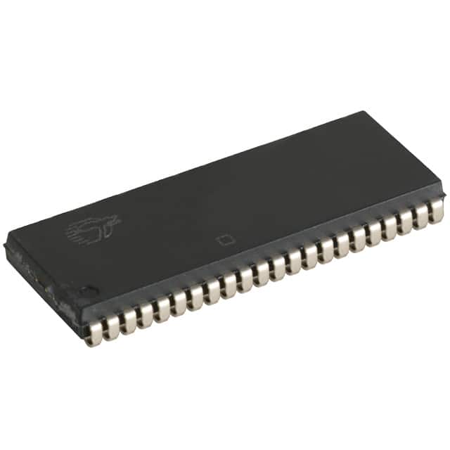
- Part No.:
- CY7C1041G30-10VXI
- Manufacturer:
- Infineon Technologies
- Category:
- Memory
- Package:
- 44-BSOJ (0.400", 10.16mm Width)
- Datasheet:
-
 CY7C1041G30-10VXI.pdf
- Description:
- IC SRAM 4MBIT PARALLEL 44SOJ
- Quantity:
- Payment:

- Shipping:

Inventory:489
Please send an inquiry. Send us your inquiry, and we will respond immediately.
Product details
Overview
CY7C1041G30-10VXI from Infineon Technologies (formerly Cypress) is a 4-Mbit (256K × 16-bit) CMOS static RAM with embedded single-bit error-correcting code (ECC), designed for high-reliability industrial memory subsystems operating at 10 ns access time under 2.2–3.6 V supply. It features TTL-compatible I/O, ERR output pin for real-time ECC event indication, and low standby current (6 mA typical). Used in programmable logic controllers and safety-critical data buffers where bit-flip resilience is required.
For engineers reviewing the CY7C1041G30-10VXI datasheet, CY7C1041G30-10VXI pinout, CY7C1041G30-10VXI application, or CY7C1041G30-10VXI equivalent, key selection criteria include verified ECC correction capability, 10 ns tAA timing across 2.2–3.6 V operation, ERR pin functionality, 48-ball VFBGA (BVXI) package mapping, and industrial temperature support (–40 °C to +85 °C).
Technical Context
This SRAM integrates dedicated ECC encoder/decoder circuitry that detects and corrects single-bit errors on every read cycle without requiring external logic. The ERR pin asserts HIGH only during successful correction events - no automatic write-back occurs, preserving deterministic timing behavior.
It supports byte-level writes via independent BHE (I/O8–I/O15) and BLE (I/O0–I/O7) controls, and operates across three voltage ranges: 1.65–2.2 V, 2.2–3.6 V, and 4.5–5.5 V. The -30 speed grade guarantees 10 ns address-to-data access (tAA) at 2.2–3.6 V, with active current of 38 mA typical and data retention down to 1.0 V.
Key Specifications
| Parameter | Value and Actual Design Meaning |
|---|---|
| Memory density | 4 Mbit (256K words × 16-bit); enables compact 512 KB data storage per device in space-constrained industrial controllers. |
| Access time (tAA) | 10 ns at VCC = 2.2–3.6 V; ensures deterministic timing for real-time firmware execution and fast buffer access. |
| ECC capability | Single-bit error detection and correction per read cycle; reduces uncorrectable error rate to <0.1 FIT/Mb per AN88889. |
| Supply voltage range | 2.2 V to 3.6 V (primary); supports legacy 3.3 V systems and mixed-voltage board designs without level shifters. |
| Standby current (ISB2) | 6 mA typical at TA = 25 °C; lowers power budget in always-on monitoring modules during idle states. |
| Operating temperature | –40 °C to +85 °C (Industrial grade); validated for deployment in factory automation and outdoor telemetry enclosures. |
| Package | 48-ball VFBGA (6 × 8 × 1.0 mm, BVXI); provides fine-pitch, low-profile footprint compatible with automated SMT assembly. |
Pinout & Package
48-ball VFBGA (BVXI) package with 0.5 mm ball pitch, JEDEC-compliant mechanical outline, and exposed thermal pad not connected internally. Pin functions mapped per Figure 2 in datasheet Rev. *N.
| Pin/Terminal | Circuit Role | Design Meaning |
|---|---|---|
| A0–A17 | Address inputs | 18-bit address bus supporting full 256K-word addressing; A17 is MSB for 4-Mbit capacity. |
| I/O0–I/O15 | Bidirectional data bus | 16-bit parallel interface; split into upper (I/O8–I/O15) and lower (I/O0–I/O7) bytes for selective writes. |
| CE | Chip Enable | Active-low global enable; places all I/Os in high-impedance state when HIGH, enabling multi-chip memory expansion. |
| OE | Output Enable | Active-low control for read data gating; allows interleaved read/write cycles without bus contention. |
| WE | Write Enable | Active-low signal initiating write cycle; synchronized with CE and byte enables for precise timing control. |
| BHE / BLE | Byte High/Low Enable | Independent controls for upper/lower byte writes; eliminates need for external byte masking logic. |
| ERR | Error indication output | Open-drain HIGH pulse during single-bit correction; used for system-level fault logging or diagnostic interrupt generation. |
| VCC / VSS | Power / Ground | Dual VCC pins (balls C4, D4) reduce IR drop; dedicated VSS balls (C5, D5, E5, F5) improve noise immunity. |
Key Features
| Feature | Design Value |
|---|---|
| Embedded ECC engine | On-die correction logic eliminates external Hamming code ICs and associated PCB routing complexity. |
| ERR output pin | Dedicated open-drain indicator confirms correction occurrence - enables real-time reliability monitoring without polling. |
| Multi-voltage support | Three discrete VCC ranges allow direct integration into 1.8 V, 3.3 V, and 5 V subsystems without regulators or translators. |
| Low-power standby mode | 6 mA ISB2 at 2.2–3.6 V enables >10-year battery-backed data retention in remote sensor nodes. |
| TTL-compatible I/O | VIH/VIL thresholds match legacy 3.3 V microcontrollers and FPGAs - no level-shifter required in most designs. |
Applications
| Programmable Logic Controller (PLC) Data Buffer | Industrial HMI Display Frame Memory |
|---|---|
|
Use Scenario: Stores runtime variable tables and I/O image data in PLC main CPU modules where electromagnetic interference may cause memory bit flips. IC Role / Device Role / Timing Role: Primary working RAM with ECC-protected read path; 10 ns tAA meets deterministic scan-cycle timing budgets. Use Value: Prevents silent data corruption in safety-critical ladder logic execution - eliminates need for software checksum overhead. |
Use Scenario: Holds GUI frame buffers for 7-inch resistive touch HMIs deployed in manufacturing cells with high ambient EMI. IC Role / Device Role / Timing Role: Dual-port-accessible display memory; ERR pin triggers watchdog reset if unrecoverable error count exceeds threshold. Use Value: Ensures visual integrity of machine status indicators - avoids misinterpretation of alarm states due to memory errors. |
| Railway Signaling Event Logger | Medical Diagnostic Equipment Configuration Store |
|
Use Scenario: Captures timestamped train position reports and interlocking commands in EN 5012x-certified signaling hardware. IC Role / Device Role / Timing Role: Nonvolatile backup memory with 1.0 V data retention; retains logs during brownout events lasting up to 100 ms. Use Value: Guarantees forensic traceability of safety events - satisfies SIL-4 data integrity requirements without FRAM cost premium. |
Use Scenario: Stores calibration coefficients and patient protocol settings in portable ultrasound units subject to vibration and thermal cycling. IC Role / Device Role / Timing Role: Configuration SRAM accessed during boot sequence; ECC prevents corrupted gain/offset values from propagating to imaging pipeline. Use Value: Avoids false-positive artifact generation in B-mode scans - maintains diagnostic accuracy per IEC 62304 Class C software requirements. |
Equivalent & Alternatives
The following parts are listed as comparable options for similar ECC SRAM applications.
| Alternative Part | Technical Difference | Application Difference | Selection Advice |
|---|---|---|---|
| IS61WV25616EDBLL-10MLI | No integrated ECC; requires external error-handling logic; 10 ns tAA at 3.3 V; 48-pin TSOP II package. | Lacks real-time ERR indication; increases firmware complexity for error reporting and recovery. | Choose only if board layout constraints prohibit VFBGA or if ECC is implemented in host processor firmware. |
| AS6C4008-10TIN | 4-Mbit non-ECC SRAM; 10 ns tAA; 32-pin SOJ; no ERR pin; higher ISB2 (15 mA typical). | Relies on system-level redundancy or periodic scrubbing; unsuitable for zero-tolerance error environments. | Select when cost sensitivity outweighs reliability requirements and thermal/power margins permit higher standby draw. |
Compared with IS61WV25616EDBLL-10MLI and AS6C4008-10TIN, CY7C1041G30-10VXI delivers verified on-die ECC correction with hardware-asserted ERR signaling - reducing firmware validation scope and eliminating external error-handling components while maintaining identical 10 ns timing and industrial temperature compliance.
Availability
CY7C1041G30-10VXI is available at Aetrix Electronics and suitable for programmable logic controllers, industrial HMIs, and railway signaling systems requiring stable component supply across extended product lifecycles.
Supply support for CY7C1041G30-10VXI includes scheduled delivery planning, volume procurement assistance, BOM continuity management, traceable sourcing, and lifecycle availability coordination for OEM customers, industrial embedded developers, connected-device designers, and electronics production programs.
Manufacturer
Infineon Technologies is a global semiconductor leader headquartered in Munich, Germany, specializing in power management, automotive MCUs, and high-reliability memory solutions.
CY7C1041G30-10VXI belongs to Infineon's legacy Cypress SRAM portfolio, engineered specifically for industrial and transportation applications demanding deterministic timing, ECC resilience, and long-term supply assurance.
FAQ
Does CY7C1041G30-10VXI support automatic error correction write-back?
No. The device performs single-bit error correction during read cycles and asserts the ERR pin, but does not automatically rewrite corrected data back to the memory array. Host firmware must initiate any corrective write if persistent storage of corrected values is required. This design preserves strict timing predictability and avoids unintended write amplification.
What is the function of the ERR pin, and how is it electrically driven?
The ERR pin is an open-drain output that drives HIGH only when a single-bit error is detected and corrected during a read access. It remains LOW or high-impedance otherwise. A pull-up resistor (typically 4.7 kΩ to VCC) is required externally to generate a valid logic HIGH level for host interrupt or status monitoring.
Can CY7C1041G30-10VXI operate at 1.8 V supply?
No. The "30" speed grade is specified only for the 2.2–3.6 V VCC range. For 1.65–2.2 V operation, the CY7C1041G18-15VXI variant (15 ns access) must be used. Attempting 1.8 V operation on the -30 grade violates datasheet limits and risks timing violations or ECC functional failure.
How does the BVXI VFBGA package differ from BVJXI in pin mapping?
The BVXI and BVJXI packages share identical mechanical dimensions and ball count, but swap the physical locations of upper-byte (I/O8–I/O15) and lower-byte (I/O0–I/O7) I/O balls. BVXI follows standard byte ordering; BVJXI reverses it per JEDEC compliance. Layouts must match the specific package grade to avoid data bus inversion.
CY7C1041G30-10VXI Specifications
- Product attributes
- Attribute value
- Manufacturer:
- Infineon Technologies
- Series:
- -
- Package/Case:
- 44-BSOJ (0.400", 10.16mm Width)
- Packaging:
- Tube
- Product Status:
- Active
- Programmable:
- Not Verified
- Memory Type:
- Volatile
- Memory Format:
- SRAM
- Technology:
- SRAM - Asynchronous
- Memory Size:
- 4Mbit
- Memory Organization:
- 256K x 16
- Memory Interface:
- Parallel
- Clock Frequency:
- -
- Write Cycle Time - Word, Page:
- 10ns
- Access Time:
- 10 ns
- Voltage - Supply:
- 2.2V ~ 3.6V
- Operating Temperature:
- -40°C ~ 85°C (TA)
- Grade:
- -
- Qualification:
- -
- Mounting Type:
- Surface Mount
- Supplier Device Package:
- 44-SOJ
CY7C1041G30-10VXI FAQ
1.How can I place an order for CY7C1041G30-10VXI through Aetrix?
Please submit a Request for Quotation (RFQ) for CY7C1041G30-10VXI on Aetrix. Our sales agent will provide a competitive quotation and guide you through the order confirmation once you accept the terms.
2.Are the price and stock information for CY7C1041G30-10VXI reliable?
The price and inventory of CY7C1041G30-10VXI are updated periodically and may fluctuate due to market conditions. Stock and pricing data are typically refreshed every 24 hours. Quotation validity for CY7C1041G30-10VXI is usually 5 days.
3.What payment methods are accepted for CY7C1041G30-10VXI?
We accept Wire Transfer, PayPal, Credit Card, Western Union, MoneyGram, and Escrow for CY7C1041G30-10VXI transactions.
Note: Certain payment methods may incur a processing fee.
4.How is shipping managed for CY7C1041G30-10VXI?
CY7C1041G30-10VXI orders can be shipped via leading logistics carriers, including DHL, UPS, FedEx, TNT, or Registered Mail.
Once your CY7C1041G30-10VXI order is processed, you will receive an email with the shipment details and tracking number.
Note: Tracking information may take up to 24 hours to appear. Express delivery typically takes 3–5 business days.
5.How can I obtain technical support or documentation for CY7C1041G30-10VXI?
For technical support, including CY7C1041G30-10VXI datasheets, pinout diagrams, or application guidance, please contact our engineering support team. They can provide detailed documentation and assistance for your CY7C1041G30-10VXI requirements.
6.How does Aetrix verify that CY7C1041G30-10VXI is sourced from the original manufacturer or authorized distributors?
All CY7C1041G30-10VXI products on Aetrix are procured from qualified distributors and authorized channels. Our dedicated quality assurance team conducts strict verification, including traceability checks and, if necessary, third-party testing. This ensures that CY7C1041G30-10VXI meets industry standards.
7.What is the process for return or replacement of CY7C1041G30-10VXI?
All CY7C1041G30-10VXI units undergo pre-shipment inspection (PSI). If there is an issue with CY7C1041G30-10VXI, returns or replacements are accepted under the following conditions:
1.Quantity discrepancies, incorrect items, or visible external defects (such as breakage or corrosion), acknowledged by Aetrix.
2.The issue is reported within 90 days of delivery.
3.The CY7C1041G30-10VXI part is unused and in its original packaging.
Return procedure for CY7C1041G30-10VXI:
1.Submit a request within 90 days.
2.Obtain a Return Material Authorization (RMA) from Aetrix.
CY7C1041G30-10VXI Tags

-
M24C02-WMN6TP
STMicroelectronics

-
AT24C02C-XHM-T
Microchip Technology

-
AT21CS01-STUM10-T
Microchip Technology

-
AT24C02C-SSHM-T
Microchip Technology

-
24LC01BT-I/OT
Microchip Technology

-
M24C02-FMC6TG
STMicroelectronics
-
AT24CS02-SSHM-T
Microchip Technology

-
93LC46BT-I/OT
Microchip Technology
-
AT24C04C-SSHM-T
Microchip Technology

-
24LC01BT-I/SN
Microchip Technology
-
24AA02UIDT-I/OT
Microchip Technology

-
AT24C08C-STUM-T
Microchip Technology
Tech Hub

An engineering guide to LED driver operation, constant-current and constant-voltage outputs, linear and switching topologies, dimming, IC selection, calculations, replacement compatibility, and fault c…

Operational amplifier guide covering op amp basics, feedback, ideal vs real op amps, common configurations, buffer circuits, offset, bias current, gain-bandwidth, slew rate, rail-to-rail limits and sel…

Jumper cables guide covering safe connection order, red and black clamp placement, final ground connection, cable gauge, length, clamp quality, copper vs CCA cables, jump starter comparison and battery…

LDO regulator guide covering low dropout voltage, power dissipation, thermal design, PSRR, output noise, capacitor stability, adjustable LDO circuits, LDO vs buck converter and datasheet selection chec…

Conditional Access Module guide covering CAM meaning, CI/CI+ interface, smart card authorization, DVB security workflow, TV and set-top box compatibility, internal electronics, ESD protection, connecto…

Guide to electronic component obsolescence covering EOL risk, PCN/PDN notices, last-time buy planning, replacement options, form-fit-function validation, counterfeit risk and BOM lifecycle management.

18650 battery guide covering lithium-ion cell basics, 3.6V/3.7V voltage, 4.2V charging, mAh and Wh capacity, protected cells, chargers, BMS, series-parallel packs, holders, welding and sourcing checks.…

Hall effect sensor guide covering working principle, linear and digital sensors, Arduino circuits, current sensing, speed detection, automotive applications, A3144 examples, signal filtering and datash…

Product Change Notification guide for electronic components, covering PCN meaning, PCN vs PDN/EOL, common change types, risk levels, form-fit-function review, engineering validation, BOM control, LTB/L…

A practical guide to blend door actuators, covering HVAC function, symptoms, location, AC and heater issues, reset and calibration, replacement cost, electrical diagnosis, compatibility checks, and rep…


