
 My Inquiry
 My Account


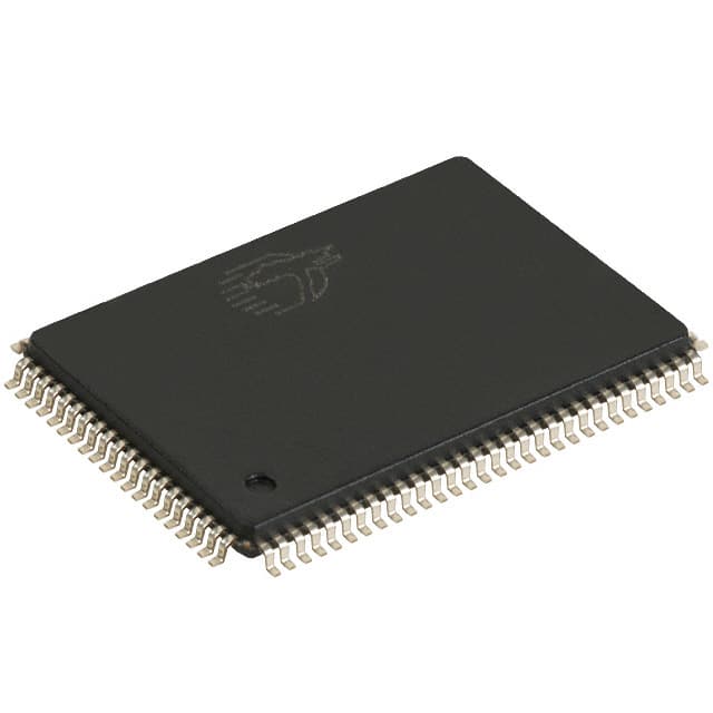
Infineon Technologies CY7C1383KVE33-133AXI
- Part No.:
- CY7C1383KVE33-133AXI
- Manufacturer:
- Infineon Technologies
- Category:
- Memory
- Package:
- 100-LQFP
- Datasheet:
-
 CY7C1383KVE33-133AXI.pdf
- Description:
- IC SRAM 18MBIT PARALLEL 100TQFP
- Quantity:
- Payment:

- Shipping:

Inventory:2,156
Please send an inquiry. Send us your inquiry, and we will respond immediately.
Product details
Overview
CY7C1383KVE33 from Cypress Semiconductor is a 18-Mbit (1M × 18) synchronous flow-through SRAM with on-chip ECC, designed for high-speed cache and buffer applications in networking and telecom systems. It supports 133 MHz bus operation, delivers 6.5 ns clock-to-output delay, operates from a 3.3 V core supply with 2.5 V/3.3 V I/O, and features interleaved/linear burst addressing via MODE pin.
For engineers reviewing the CY7C1383KVE33 datasheet, CY7C1383KVE33 pinout, CY7C1383KVE33 application, or CY7C1383KVE33 equivalent, key selection criteria include burst mode control (MODE), dual-voltage I/O (VDDQ), JTAG boundary scan support, and synchronous self-timed write capability with separate ADSP/ADSC address strobes.
Technical Context
This SRAM implements a synchronous, flow-through architecture with a 2-bit internal burst counter that auto-increments addresses on ADV assertion. All address, data, and control inputs (CE1–CE3, BWx, BWE, GW, ADSP, ADSC) are registered on the rising edge of CLK, enabling precise timing alignment with high-speed microprocessors.
The device supports two memory configurations: 1M × 18 (CY7C1383KVE33) and 512K × 36 (CY7C1381KVE33), sharing identical timing, ECC, and interface logic. ECC encoding/decoding reduces soft error rate (SER), while ZZ sleep mode preserves data integrity with asynchronous entry/exit.
Key Specifications
| Parameter | Value and Actual Design Meaning |
|---|---|
| Memory Density | 18 Mbit (1,048,576 × 18 bits) - provides full-word buffering for 18-bit wide data paths in packet processors. |
| Max Clock Frequency | 133 MHz - enables 7.5 ns cycle time for sustained burst transfers in high-throughput switching fabrics. |
| Access Time (tCO) | 6.5 ns - guarantees deterministic read latency from CLK rise to valid DQ output under worst-case conditions. |
| VDD / VDDQ | 3.3 V core / 2.5 V or 3.3 V I/O - allows interoperability with both LVTTL and SSTL-2 interfaces without level shifters. |
| Burst Mode Control | MODE pin (static strap) - selects interleaved (VDD/floating) or linear (GND) addressing for cache line compatibility. |
| ECC Support | On-chip encoder/decoder - corrects single-bit errors and detects double-bit errors per 18-bit word, reducing SER in radiation-prone environments. |
| Sleep Mode | ZZ pin (asynchronous, active HIGH) - reduces standby current to ≤10 µA while retaining memory contents without clock gating. |
Pinout & Package
Package: JEDEC-standard Pb-free 100-pin TQFP (14 × 20 × 1.4 mm), pin-compatible with CY7C1383KV33 and CY7C1381KVE33 variants.
| Pin/Terminal | Circuit Role | Design Meaning |
|---|---|---|
| CLK | Clock input | Positive-edge-triggered master timing reference for all synchronous registers and burst counter increment. |
| ADSP / ADSC | Address strobe inputs | Separate processor (ADSP) and controller (ADSC) strobes enable dual-bus system integration without arbitration logic. |
| ADV | Address advance | Controls internal address increment during burst cycles; sampled synchronously on CLK rise. |
| CE1, CE2, CE3 | Chip enable group | Three-level decode (CE1 active LOW, CE2 active HIGH, CE3 active LOW) supports depth expansion up to 8 devices. |
| BWA–BWD, BWE | Byte write controls | Four independent byte enables + global write enable allow partial or full-word writes without external masking logic. |
| DQ[17:0], DQP[3:0] | Data I/O + parity | 18-bit bidirectional data bus with 4-bit parity (DQP) for ECC - DQP lines mirror DQ behavior and are byte-aligned with BWx. |
| MODE | Burst sequence selector | Static configuration pin determining burst order (interleaved vs. linear); must remain stable during operation. |
| ZZ | Asynchronous sleep | Active-HIGH entry into low-power retention mode; no clock required; internal pull-down ensures safe default state. |
Key Features
| Feature | Design Value |
|---|---|
| Flow-through synchronous architecture | Eliminates pipeline stalls by aligning read data output with next-cycle address setup, enabling 2-1-1-1 access pattern. |
| Configurable burst addressing | Interleaved or linear burst sequences selected at power-up via MODE pin - matches Intel Pentium or Motorola PowerPC cache line formats. |
| Integrated ECC engine | Single-bit error correction and double-bit error detection per 18-bit word - reduces uncorrectable error rate by >99% in neutron-rich environments. |
| Multi-voltage I/O support | VDDQ independently configurable for 2.5 V or 3.3 V - enables direct interfacing with FPGA I/O banks or ASIC cores operating at either voltage. |
| JTAG boundary scan (IEEE 1149.1) | Full scan chain implemented on FBGA packages; TQFP variant omits TDO/TDI/TMS/TCK pins - simplifies test access in space-constrained designs. |
Applications
| Telecom Line Cards | Network Packet Buffers |
|---|---|
Use Scenario: High-speed packet buffering in OC-192/STM-64 line interface units requiring deterministic latency and error resilience. IC Role / Device Role / Timing Role: Primary data buffer between SerDes PHY and traffic manager ASIC, operating at 133 MHz with zero-wait-state burst reads. Use Value: 6.5 ns tCO and ECC ensure sub-microsecond forwarding latency and <1E-15 UBER in carrier-grade systems. | Use Scenario: Shared memory pool for multi-port Ethernet switch fabric controllers handling jumbo frames and QoS queues. IC Role / Device Role / Timing Role: Synchronous SRAM serving as unified packet descriptor store with concurrent read/write access across multiple ingress/egress engines. Use Value: Dual-voltage I/O (VDDQ = 2.5 V) matches FPGA transceiver voltage, eliminating level shifters and reducing BOM count. |
| Baseband Processing Units | Radar Signal Processors |
Use Scenario: Real-time channel estimation and FFT buffer in LTE/5G massive MIMO baseband units exposed to thermal cycling and EMI. IC Role / Device Role / Timing Role: Low-latency scratchpad memory for DSP co-processors, accessed via ADSC-controlled burst sequences synchronized to DMA triggers. Use Value: ZZ sleep mode cuts idle power by >99% during inter-frame gaps while preserving critical calibration coefficients. | Use Scenario: Pulse-Doppler radar front-end buffering where transient radiation induces soft errors in signal path memory. IC Role / Device Role / Timing Role: ECC-protected frame buffer storing ADC samples prior to digital beamforming, operating in extended temperature range. Use Value: On-chip ECC reduces SER by 3 orders of magnitude versus standard SRAM, meeting MIL-STD-883 Class B reliability requirements. |
Equivalent & Alternatives
The following parts are listed as comparable options for similar synchronous SRAM applications.
| Alternative Part | Technical Difference | Application Difference | Selection Advice |
|---|---|---|---|
| IS61WV102418BLL-133TQLI | No integrated ECC; 133 MHz, 1M × 18, 3.3 V core/2.5 V I/O; 100-pin TQFP; tCO = 7.0 ns | Lacks on-die error correction - requires external ECC logic or software mitigation for SER-critical use cases. | Select when cost sensitivity outweighs radiation tolerance and system-level ECC overhead is acceptable. |
| MT48LC16M16A2P-6A:G | SDRAM (asynchronous command interface), 256 Mbit, 16M × 16, 3.3 V; 54-pin TSOP; 6 ns CL | Requires refresh management, command sequencing, and burst-length configuration - increases controller complexity and latency jitter. | Select only when higher density and lower cost justify added controller firmware and timing uncertainty. |
Compared with IS61WV102418BLL-133TQLI and MT48LC16M16A2P-6A:G, CY7C1383KVE33 uniquely combines deterministic 6.5 ns access, hardware ECC, and dual-voltage I/O in a pinout-identical 100-pin TQFP package - eliminating redesign risk while enhancing reliability in mission-critical embedded systems.
Availability
CY7C1383KVE33 is available at Aetrix Electronics and suitable for telecom line cards, network packet buffers, and radar signal processors requiring stable component supply, long-term lifecycle support, and guaranteed Pb-free compliance.
Supply support for CY7C1383KVE33 includes scheduled delivery planning, volume procurement assistance, BOM continuity management, traceable sourcing, and lifecycle availability coordination for OEM customers, industrial embedded developers, connected-device designers, and electronics production programs.
Manufacturer
Cypress Semiconductor (now part of Infineon Technologies) is a fabless semiconductor company specializing in high-performance memory, PSoC programmable systems-on-chip, and USB/USB-C solutions.
CY7C1383KVE33 belongs to Cypress's high-speed synchronous SRAM product line, engineered for deterministic latency, ECC resilience, and seamless integration with RISC and DSP-based architectures in infrastructure equipment.
FAQ
What is the function of the MODE pin, and how must it be configured?
The MODE pin selects burst addressing order: HIGH (or floating, due to internal pull-up) enables interleaved bursts; LOW (tied to GND) enables linear bursts. It is a static strap pin - configuration must be fixed at power-up and cannot change during operation. Incorrect or floating MODE states may cause unpredictable burst address generation and data corruption.
Does CY7C1383KVE33 support JTAG boundary scan in the 100-pin TQFP package?
No. JTAG signals (TCK, TMS, TDI, TDO) are not bonded out in the 100-pin TQFP package per the official pinout diagram and datasheet. These pins are only available on the 165-ball FBGA variant (e.g., CY7C1381KV33). For TQFP users, boundary scan testing requires external probing or functional verification methods.
How does the ZZ sleep mode interact with ongoing burst operations?
ZZ is asynchronous and takes effect immediately upon assertion, halting all internal clocks and placing outputs in high-impedance. If asserted mid-burst, the current access completes before sleep activation; no data loss occurs. The device retains all stored data and resumes normal operation within 100 ns after ZZ returns LOW, with no reinitialization required.
Can DQP[3:0] parity pins be disabled or repurposed as general I/O?
No. DQP pins are dedicated parity I/O lines tied directly to the ECC encoder/decoder and cannot be disabled or reassigned. They operate synchronously with DQ[17:0], share the same byte-write controls (BWA–BWD), and must be terminated per JEDEC-compliant 2.5 V/3.3 V I/O guidelines - omitting or misrouting them compromises ECC functionality and memory integrity.
CY7C1383KVE33-133AXI Specifications
- Product attributes
- Attribute value
- Manufacturer:
- Infineon Technologies
- Series:
- -
- Package/Case:
- 100-LQFP
- Packaging:
- Tray
- Product Status:
- Active
- Programmable:
- Not Verified
- Memory Type:
- Volatile
- Memory Format:
- SRAM
- Technology:
- SRAM - Synchronous, SDR
- Memory Size:
- 18Mbit
- Memory Organization:
- 1M x 18
- Memory Interface:
- Parallel
- Clock Frequency:
- 133 MHz
- Write Cycle Time - Word, Page:
- -
- Access Time:
- 6.5 ns
- Voltage - Supply:
- 3.135V ~ 3.6V
- Operating Temperature:
- -40°C ~ 85°C (TA)
- Grade:
- -
- Qualification:
- -
- Mounting Type:
- Surface Mount
- Supplier Device Package:
- 100-TQFP (14x20)
CY7C1383KVE33-133AXI FAQ
1.How can I place an order for CY7C1383KVE33-133AXI through Aetrix?
Please submit a Request for Quotation (RFQ) for CY7C1383KVE33-133AXI on Aetrix. Our sales agent will provide a competitive quotation and guide you through the order confirmation once you accept the terms.
2.Are the price and stock information for CY7C1383KVE33-133AXI reliable?
The price and inventory of CY7C1383KVE33-133AXI are updated periodically and may fluctuate due to market conditions. Stock and pricing data are typically refreshed every 24 hours. Quotation validity for CY7C1383KVE33-133AXI is usually 5 days.
3.What payment methods are accepted for CY7C1383KVE33-133AXI?
We accept Wire Transfer, PayPal, Credit Card, Western Union, MoneyGram, and Escrow for CY7C1383KVE33-133AXI transactions.
Note: Certain payment methods may incur a processing fee.
4.How is shipping managed for CY7C1383KVE33-133AXI?
CY7C1383KVE33-133AXI orders can be shipped via leading logistics carriers, including DHL, UPS, FedEx, TNT, or Registered Mail.
Once your CY7C1383KVE33-133AXI order is processed, you will receive an email with the shipment details and tracking number.
Note: Tracking information may take up to 24 hours to appear. Express delivery typically takes 3–5 business days.
5.How can I obtain technical support or documentation for CY7C1383KVE33-133AXI?
For technical support, including CY7C1383KVE33-133AXI datasheets, pinout diagrams, or application guidance, please contact our engineering support team. They can provide detailed documentation and assistance for your CY7C1383KVE33-133AXI requirements.
6.How does Aetrix verify that CY7C1383KVE33-133AXI is sourced from the original manufacturer or authorized distributors?
All CY7C1383KVE33-133AXI products on Aetrix are procured from qualified distributors and authorized channels. Our dedicated quality assurance team conducts strict verification, including traceability checks and, if necessary, third-party testing. This ensures that CY7C1383KVE33-133AXI meets industry standards.
7.What is the process for return or replacement of CY7C1383KVE33-133AXI?
All CY7C1383KVE33-133AXI units undergo pre-shipment inspection (PSI). If there is an issue with CY7C1383KVE33-133AXI, returns or replacements are accepted under the following conditions:
1.Quantity discrepancies, incorrect items, or visible external defects (such as breakage or corrosion), acknowledged by Aetrix.
2.The issue is reported within 90 days of delivery.
3.The CY7C1383KVE33-133AXI part is unused and in its original packaging.
Return procedure for CY7C1383KVE33-133AXI:
1.Submit a request within 90 days.
2.Obtain a Return Material Authorization (RMA) from Aetrix.
CY7C1383KVE33-133AXI Tags

-
M24C02-WMN6TP
STMicroelectronics

-
AT24C02C-XHM-T
Microchip Technology

-
AT21CS01-STUM10-T
Microchip Technology

-
AT24C02C-SSHM-T
Microchip Technology

-
24LC01BT-I/OT
Microchip Technology

-
M24C02-FMC6TG
STMicroelectronics
-
AT24CS02-SSHM-T
Microchip Technology

-
93LC46BT-I/OT
Microchip Technology
-
AT24C04C-SSHM-T
Microchip Technology

-
24LC01BT-I/SN
Microchip Technology
-
24AA02UIDT-I/OT
Microchip Technology

-
AT24C08C-STUM-T
Microchip Technology
Tech Hub

A practical engineering and sourcing framework covering lifecycle verification, lifetime-buy calculations, replacement qualification, supplier checks and counterfeit-risk controls.

TTL and CMOS logic families differ in thresholds, loading, output drive, power and timing. This engineering guide compares 74HC and 74HCT, calculates noise margins and checks 3.3 V/5 V compatibility.

A practical engineering guide to 3.3V and 5V logic compatibility, input thresholds, resistor dividers, translator ICs, MOSFET level shifting, I2C pull-ups, timing limits and power-sequencing risks.

The 74HC595 uses push-pull logic outputs, while the TPIC6B595 uses 50 V open-drain DMOS sinks for higher-power loads. This guide compares timing, current limits, 3.3 V interfacing, load wiring, thermal…

The 74HC595 converts serial data into eight stable parallel outputs. This guide covers pin functions, shift and storage timing, OE and MR behavior, drive-current limits, cascading, voltage compatibilit…

A technical comparison of level-sensitive latches and edge-triggered flip-flops, covering timing windows, setup and hold limits, master–slave operation, time borrowing, race-through, HDL inference and…

A D latch stores one bit while Enable controls when data can pass. This reference covers gate-level operation, truth tables, transparency, setup and hold timing, LE versus OE, common ICs and practical …

An SR latch stores one bit through cross-coupled feedback. This engineering reference covers NOR and NAND implementations, truth tables, forbidden-state recovery, gated operation, switch debouncing, fa…

Latch circuits retain one bit through feedback. This technical reference covers SR and D latches, truth tables, transparency, timing limits, latch-versus-flip-flop behavior, applications and common log…

An engineering guide to LED driver operation, constant-current and constant-voltage outputs, linear and switching topologies, dimming, IC selection, calculations, replacement compatibility, and fault c…


