
 My Inquiry
 My Account


Infineon Technologies CY7C1460AV25-167BZXI
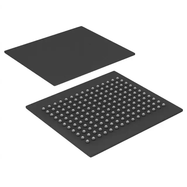
- Part No.:
- CY7C1460AV25-167BZXI
- Manufacturer:
- Infineon Technologies
- Category:
- Memory
- Package:
- 165-LBGA
- Datasheet:
-
 CY7C1460AV25-167BZXI.pdf
- Description:
- IC SRAM 36MBIT PAR 165FBGA
- Quantity:
- Payment:

- Shipping:

Inventory:3,889
Please send an inquiry. Send us your inquiry, and we will respond immediately.
Product details
Overview
CY7C1460AV25-167BZXI from Cypress Semiconductor is a 36-Mbit synchronous pipelined SRAM (1M × 36 configuration) implementing No Bus Latency™ (NoBL™) architecture, designed for high-throughput memory subsystems in networking and telecom data-path applications. It operates at 167 MHz with 3.4 ns clock-to-output delay, 2.5 V core supply, 2.5 V/1.8 V I/O supply, and supports zero-wait-state back-to-back read/write operations.
For engineers reviewing the CY7C1460AV25-167BZXI datasheet, CY7C1460AV25-167BZXI pinout, CY7C1460AV25-167BZXI application, or CY7C1460AV25-167BZXI equivalent, key selection criteria include burst order control (linear/interleaved), byte-write select granularity (BWa–BWd), synchronous self-timed write timing, and JEDEC-standard 100-pin TQFP packaging with JTAG boundary-scan support.
Technical Context
This SRAM implements fully registered pipelined operation: all address, control, and data inputs are latched on the rising edge of CLK, and all outputs are registered to that same edge. The internal NoBL logic eliminates bus latency by enabling consecutive read/write cycles without wait states, using synchronous self-timed write circuitry and three-level chip enable decoding (CE1 active-low, CE2 active-high, CE3 active-low).
Burst capability is configurable via the MODE strap pin (interleaved or linear), and low-power operation is supported through asynchronous ZZ sleep mode and CEN-controlled clock gating. Output drivers are synchronously three-stated during write data phases to prevent bus contention, and IEEE 1149.1 JTAG boundary scan is integrated for system-level testability.
Key Specifications
| Parameter | Value and Actual Design Meaning |
|---|---|
| Memory Density | 36 Mbit (1,048,576 × 36 bits) - supports 4-byte aligned word access in 1M×36 configuration |
| Max Clock Frequency | 167 MHz - enables sustained 167 million transfers per second in pipelined mode |
| Access Time (tCO) | 3.4 ns - guaranteed clock-to-output delay at 167 MHz, critical for timing closure in high-speed bus interfaces |
| Core Supply Voltage | 2.5 V ± 0.2 V - defines internal logic voltage domain and power consumption envelope |
| I/O Supply Voltage | 2.5 V or 1.8 V - selectable I/O interface voltage supporting mixed-voltage system integration |
| Byte Write Control | BWa–BWd (4 independent signals) - enables selective 9-bit writes to DQa–DQd and parity lines DQPa–DQPd |
| Package | 100-pin TQFP (14 × 14 mm, 0.5 mm pitch) - JEDEC-standard footprint compatible with automated SMT assembly |
Pinout & Package
Package: 100-pin Thin Quad Flat Package (TQFP), lead-free compliant, body size 14 mm × 14 mm, pitch 0.5 mm, 1.4 mm height.
| Pin/Terminal | Circuit Role | Design Meaning |
|---|---|---|
| A0–A19 | Synchronous Address Input | Latched on rising CLK edge; selects one of 1M addresses in 1M×36 mode |
| BWa–BWd | Synchronous Byte Write Select | Active-low per-byte controls for DQa/DQPa through DQd/DQPd; qualified by WE and CLK |
| CLK | Primary Clock Input | Rising-edge-triggered master clock; gated by CEN; drives all input/output registers |
| CEN | Clock Enable | Active-low signal that masks CLK without deselecting device-extends previous cycle |
| CE1, CE3 | Chip Enable (active-low) | Two of three synchronous enables; all three (CE1, CE2, CE3) must be asserted for access |
| CE2 | Chip Enable (active-high) | Third synchronous enable; complements CE1/CE3 for flexible bank decoding |
| OE | Asynchronous Output Enable | Active-low; tri-states outputs during write phases regardless of OE state |
| WE | Write Enable | Active-low synchronous control; initiates write when sampled with CEN LOW and CEx asserted |
| DQa–DQd / DQPa–DQPd | Bidirectional Data I/O | 36-bit data + 4-bit parity; direction controlled by OE and internal logic; registered I/O |
| ADV/LD | Address Advance/Load | HIGH advances internal burst counter; LOW loads new address-required after deselect |
| MODE | Burst Order Strap | Static input: HIGH = interleaved burst, LOW = linear burst; must not toggle during operation |
| ZZ | Asynchronous Sleep | Active-high entry into low-power sleep mode with data retention; internal pull-down |
| VDD | Core Power Supply | 2.5 V supply for internal logic and memory array; decoupling required per datasheet layout guidelines |
| VDDQ | I/O Power Supply | 2.5 V or 1.8 V supply for DQ/DQP buffers-enables mixed-voltage interface compatibility |
| VSS | Ground | Common reference for core and I/O domains; multiple pins provided for low-inductance return paths |
Key Features
| Feature | Design Value |
|---|---|
| No Bus Latency™ Architecture | Enables true back-to-back read/write operations with zero wait states-eliminates pipeline stalls in burst-intensive data paths |
| Full Input/Output Registration | All address, control, and data signals synchronized to CLK rising edge-simplifies timing analysis and PCB layout |
| Synchronous Self-Timed Writes | On-chip write timing control removes external write-pulse width constraints-reduces system-level timing margining |
| Configurable Burst Order | MODE pin selects linear or interleaved burst sequence-matches legacy ZBT or modern cache-line access patterns |
| JTAG Boundary Scan (IEEE 1149.1) | Integrated test infrastructure supports board-level interconnect verification without additional test fixtures |
| Flexible Power Management | Independent CEN clock gating and ZZ sleep mode allow granular power control across operational modes |
Applications
| Network Packet Buffering | Telecom Line Card Memory |
|---|---|
|
Use Scenario: Storing and forwarding variable-length Ethernet/IP packets in Layer 2/3 switches with strict latency budgets. IC Role / Device Role / Timing Role: High-bandwidth, low-latency shared memory buffer interfacing directly to packet ASICs via source-synchronous parallel bus. Use Value: 167 MHz pipelined throughput and 3.4 ns tCO ensure deterministic packet queuing latency under full line-rate traffic. |
Use Scenario: Frame buffering in OC-48/STM-16 SONET/SDH line cards requiring burst-mode access to ATM cells or GFP frames. IC Role / Device Role / Timing Role: Dual-port-capable SRAM used as FIFO and descriptor table storage for framer and mapper ICs. Use Value: Byte-write select (BWa–BWd) enables efficient partial-cell updates without full-word overwrites, reducing bus traffic. |
| Baseband Processing Cache | Industrial Real-Time Controller Memory |
|
Use Scenario: Temporary storage of channelized TDMA bursts in wireless base station transceivers before modulation/demodulation. IC Role / Device Role / Timing Role: Low-jitter, registered memory interfacing to FPGA-based digital front-end processors. Use Value: Fully registered I/O and CEN-controlled clock gating minimize setup/hold violations in multi-FPGA timing domains. |
Use Scenario: Deterministic instruction/data storage for motion-control PLCs executing hard real-time servo loops. IC Role / Device Role / Timing Role: Zero-wait-state SRAM backing CPU instruction cache and I/O mapping registers. Use Value: ZZ sleep mode reduces standby current to <120 mA while preserving data integrity during idle cycles. |
Equivalent & Alternatives
The following parts are listed as comparable options for similar synchronous pipelined SRAM applications.
| Alternative Part | Technical Difference | Application Difference | Selection Advice |
|---|---|---|---|
| CY7C1460AV25-250BZXI | Higher speed grade: 250 MHz max, 2.6 ns tCO vs. 3.4 ns; identical pinout and feature set | Required where system clock exceeds 167 MHz or sub-3 ns output timing is mandatory | Select when bandwidth >2.68 Gb/s (167 MHz × 36-bit) is needed; otherwise, -167BZXI offers better power efficiency |
| IDT72V2115L10PF | 36-Mbit ZBT SRAM, 10 ns async access; lacks NoBL architecture, no self-timed writes, different pinout | Legacy designs requiring pin-compatible ZBT replacement without architectural changes | Use only if migrating from ZBT and retaining existing timing margins; not drop-in for NoBL-specific features |
Compared with CY7C1460AV25-250BZXI, the -167BZXI trades 83 MHz bandwidth for lower dynamic power (335 mA vs. 435 mA) and relaxed timing closure. Against IDT72V2115L10PF, it delivers true zero-wait-state pipelining but requires redesign for NoBL-specific control sequencing and burst behavior.
Availability
CY7C1460AV25-167BZXI is available at Aetrix Electronics and suitable for network packet buffering, telecom line card memory, baseband processing cache, and industrial real-time controller memory requiring stable component supply across extended production lifecycles.
Supply support for CY7C1460AV25-167BZXI includes scheduled delivery planning, volume procurement assistance, BOM continuity management, traceable sourcing, and lifecycle availability coordination for OEM customers, industrial embedded developers, connected-device designers, and electronics production programs.
Manufacturer
Cypress Semiconductor (now part of Infineon Technologies) is a fabless semiconductor company specializing in high-performance memory, microcontrollers, and programmable analog/digital ICs for industrial, automotive, and communications markets.
CY7C1460AV25 belongs to Cypress's NoBL™ SRAM product line, engineered specifically to replace asynchronous and ZBT SRAMs in bandwidth-constrained, low-latency data-path applications where deterministic pipelined access is critical.
FAQ
What is the function of the MODE pin on CY7C1460AV25-167BZXI?
The MODE pin is a static strap input that configures burst order: tied HIGH for interleaved burst (e.g., 0,2,4,6,1,3,5,7), pulled LOW for linear burst (e.g., 0,1,2,3,4,5,6,7). It must be set before initialization and remain stable during operation; floating defaults to HIGH (interleaved). This setting directly affects address sequencing during burst reads/writes and must match the host controller's expectation.
How does the ZZ pin interact with CEN and power states?
ZZ is an asynchronous active-high sleep input that places the device in a non-time-critical low-power state with data retention; it overrides CEN and halts all internal clocks. When ZZ is HIGH, core and I/O supplies remain active but dynamic current drops significantly (<120 mA). CEN remains functional upon exit from ZZ sleep, allowing immediate resumption of clocked operation without reset. ZZ has an internal pull-down, so leaving it unconnected defaults to active LOW (normal operation).
Can CY7C1460AV25-167BZXI operate with 1.8 V I/O supply while maintaining 2.5 V core?
Yes-the device supports independent VDDQ (1.8 V or 2.5 V) and VDD (2.5 V ± 0.2 V) supplies. When VDDQ = 1.8 V, all DQ/DQP I/O levels conform to 1.8 V LVTTL/LVCMOS specifications, while internal logic and memory array continue operating at 2.5 V. This allows seamless interfacing with 1.8 V FPGAs or ASICs without level shifters, provided VDDQ and VDD are powered in correct sequence per datasheet recommendations.
What happens to outputs during a write cycle when OE is asserted LOW?
During the data portion of a write cycle, outputs are synchronously three-stated regardless of OE state-this is enforced by internal control logic to prevent bus contention. OE only governs output enable during read cycles and idle states. After the write data phase completes, outputs return to tri-state unless a read is initiated in the next cycle. This behavior is inherent to the NoBL architecture and requires no external OE timing coordination.
CY7C1460AV25-167BZXI Specifications
- Product attributes
- Attribute value
- Manufacturer:
- Infineon Technologies
- Series:
- NoBL™
- Package/Case:
- 165-LBGA
- Packaging:
- Tray
- Product Status:
- Obsolete
- Programmable:
- Not Verified
- Memory Type:
- Volatile
- Memory Format:
- SRAM
- Technology:
- SRAM - Synchronous, SDR
- Memory Size:
- 36Mbit
- Memory Organization:
- 1M x 36
- Memory Interface:
- Parallel
- Clock Frequency:
- 167 MHz
- Write Cycle Time - Word, Page:
- -
- Access Time:
- 3.4 ns
- Voltage - Supply:
- 2.375V ~ 2.625V
- Operating Temperature:
- -40°C ~ 85°C (TA)
- Grade:
- -
- Qualification:
- -
- Mounting Type:
- Surface Mount
- Supplier Device Package:
- 165-FBGA (15x17)
CY7C1460AV25-167BZXI FAQ
1.How can I place an order for CY7C1460AV25-167BZXI through Aetrix?
Please submit a Request for Quotation (RFQ) for CY7C1460AV25-167BZXI on Aetrix. Our sales agent will provide a competitive quotation and guide you through the order confirmation once you accept the terms.
2.Are the price and stock information for CY7C1460AV25-167BZXI reliable?
The price and inventory of CY7C1460AV25-167BZXI are updated periodically and may fluctuate due to market conditions. Stock and pricing data are typically refreshed every 24 hours. Quotation validity for CY7C1460AV25-167BZXI is usually 5 days.
3.What payment methods are accepted for CY7C1460AV25-167BZXI?
We accept Wire Transfer, PayPal, Credit Card, Western Union, MoneyGram, and Escrow for CY7C1460AV25-167BZXI transactions.
Note: Certain payment methods may incur a processing fee.
4.How is shipping managed for CY7C1460AV25-167BZXI?
CY7C1460AV25-167BZXI orders can be shipped via leading logistics carriers, including DHL, UPS, FedEx, TNT, or Registered Mail.
Once your CY7C1460AV25-167BZXI order is processed, you will receive an email with the shipment details and tracking number.
Note: Tracking information may take up to 24 hours to appear. Express delivery typically takes 3–5 business days.
5.How can I obtain technical support or documentation for CY7C1460AV25-167BZXI?
For technical support, including CY7C1460AV25-167BZXI datasheets, pinout diagrams, or application guidance, please contact our engineering support team. They can provide detailed documentation and assistance for your CY7C1460AV25-167BZXI requirements.
6.How does Aetrix verify that CY7C1460AV25-167BZXI is sourced from the original manufacturer or authorized distributors?
All CY7C1460AV25-167BZXI products on Aetrix are procured from qualified distributors and authorized channels. Our dedicated quality assurance team conducts strict verification, including traceability checks and, if necessary, third-party testing. This ensures that CY7C1460AV25-167BZXI meets industry standards.
7.What is the process for return or replacement of CY7C1460AV25-167BZXI?
All CY7C1460AV25-167BZXI units undergo pre-shipment inspection (PSI). If there is an issue with CY7C1460AV25-167BZXI, returns or replacements are accepted under the following conditions:
1.Quantity discrepancies, incorrect items, or visible external defects (such as breakage or corrosion), acknowledged by Aetrix.
2.The issue is reported within 90 days of delivery.
3.The CY7C1460AV25-167BZXI part is unused and in its original packaging.
Return procedure for CY7C1460AV25-167BZXI:
1.Submit a request within 90 days.
2.Obtain a Return Material Authorization (RMA) from Aetrix.
CY7C1460AV25-167BZXI Tags

-
M24C02-WMN6TP
STMicroelectronics

-
AT24C02C-XHM-T
Microchip Technology

-
AT21CS01-STUM10-T
Microchip Technology

-
AT24C02C-SSHM-T
Microchip Technology

-
24LC01BT-I/OT
Microchip Technology

-
M24C02-FMC6TG
STMicroelectronics
-
AT24CS02-SSHM-T
Microchip Technology

-
93LC46BT-I/OT
Microchip Technology
-
AT24C04C-SSHM-T
Microchip Technology

-
24LC01BT-I/SN
Microchip Technology
-
24AA02UIDT-I/OT
Microchip Technology

-
AT24C08C-STUM-T
Microchip Technology
Tech Hub

Latch circuits retain one bit through feedback. This technical reference covers SR and D latches, truth tables, transparency, timing limits, latch-versus-flip-flop behavior, applications and common log…

An engineering guide to LED driver operation, constant-current and constant-voltage outputs, linear and switching topologies, dimming, IC selection, calculations, replacement compatibility, and fault c…

Operational amplifier guide covering op amp basics, feedback, ideal vs real op amps, common configurations, buffer circuits, offset, bias current, gain-bandwidth, slew rate, rail-to-rail limits and sel…

Jumper cables guide covering safe connection order, red and black clamp placement, final ground connection, cable gauge, length, clamp quality, copper vs CCA cables, jump starter comparison and battery…

LDO regulator guide covering low dropout voltage, power dissipation, thermal design, PSRR, output noise, capacitor stability, adjustable LDO circuits, LDO vs buck converter and datasheet selection chec…

Conditional Access Module guide covering CAM meaning, CI/CI+ interface, smart card authorization, DVB security workflow, TV and set-top box compatibility, internal electronics, ESD protection, connecto…

Guide to electronic component obsolescence covering EOL risk, PCN/PDN notices, last-time buy planning, replacement options, form-fit-function validation, counterfeit risk and BOM lifecycle management.

18650 battery guide covering lithium-ion cell basics, 3.6V/3.7V voltage, 4.2V charging, mAh and Wh capacity, protected cells, chargers, BMS, series-parallel packs, holders, welding and sourcing checks.…

Hall effect sensor guide covering working principle, linear and digital sensors, Arduino circuits, current sensing, speed detection, automotive applications, A3144 examples, signal filtering and datash…

Product Change Notification guide for electronic components, covering PCN meaning, PCN vs PDN/EOL, common change types, risk levels, form-fit-function review, engineering validation, BOM control, LTB/L…


