
 My Inquiry
 My Account


Infineon Technologies CY7C421-20JXI
- Part No.:
- CY7C421-20JXI
- Manufacturer:
- Infineon Technologies
- Category:
- FIFOs Memory
- Package:
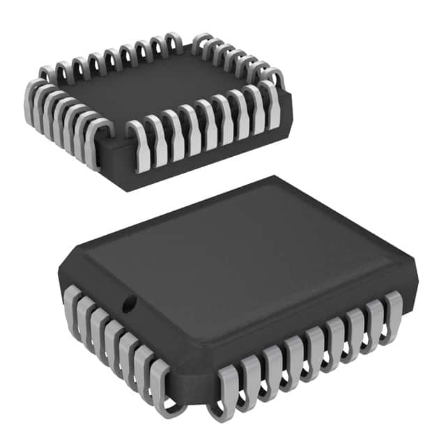
- 32-LCC (J-Lead)
- Datasheet:
-
 CY7C421-20JXI.pdf
- Description:
- IC FIFO ASYNC 512X9 20NS 32PLCC
- Quantity:
- Payment:

- Shipping:

Inventory:4,458
Please send an inquiry. Send us your inquiry, and we will respond immediately.
Product details
Overview
CY7C421-20JXI from Cypress Semiconductor is a 512 × 9 asynchronous FIFO memory IC with dual-port RAM architecture, 20 ns access time, 50 MHz max read/write clock rate, and TTL-compatible I/O. It provides independent read/write control via W/R signals, EF/FF/HF flags, and retransmit capability-used in data buffering between mismatched clock domains in industrial serial gateways and legacy bus bridges.
For engineers reviewing the CY7C421-20JXI datasheet, CY7C421-20JXI pinout, CY7C421-20JXI application, or CY7C421-20JXI equivalent, key selection criteria include asynchronous depth expansion support, half-full flag behavior in standalone mode, retransmit timing constraints, and 32-pin PLCC package compatibility with legacy PCB footprints.
Technical Context
The CY7C421-20JXI implements a true dual-port RAM core with independent write and read address pointers, enabling concurrent read/write operations without arbitration logic. Its expansion architecture uses XI/XO pins to cascade devices in depth or width, with XO repurposed as HF in non-cascaded configurations.
Retransmit functionality requires simultaneous HIGH on R and W, then toggling R to replay the last-read word; MR resets both pointers and flags. The device operates at 5 V ±10% across commercial (0°C to +70°C) and industrial (–40°C to +85°C) temperature ranges with 35 mA typical ICC1 at 20 MHz.
Key Specifications
| Parameter | Value and Actual Design Meaning |
|---|---|
| Memory Depth × Width | 512 × 9 bits - supports up to 4.6 kbit of buffered data with sequential FIFO ordering |
| Access Time | 20 ns - guarantees valid output within 20 ns after read enable assertion, critical for 50 MHz operation |
| Max Clock Rate | 50 MHz - enables 50 million read/write cycles per second, independent of FIFO fill level |
| Supply Voltage | 5 V ±10% - compatible with standard TTL logic rails and legacy 5 V system designs |
| Operating Current | 35 mA at 20 MHz - low static power draw suitable for thermally constrained industrial enclosures |
| Flag Outputs | EF, FF, HF - three dedicated open-drain/complementary flags prevent overflow/underflow and support flow control |
| ESD Protection | >2000 V HBM - meets MIL-STD-883 Class 3A requirements for board-level handling robustness |
Pinout & Package
Package: 32-pin PLCC (Plastic Leaded Chip Carrier), 11.43 mm × 11.43 mm body, 1.27 mm pitch, JEDEC MS-026AC compliant.
| Pin/Terminal | Circuit Role | Design Meaning |
|---|---|---|
| W | Write Enable Input | Active-low signal initiating write cycle; must be LOW for duration ≥20 ns to latch D0–D8 |
| R | Read Enable Input | Active-low signal enabling Q0–Q8 output drive; outputs enter high-Z when R is HIGH |
| D0–D8 | Data Inputs | 9-bit parallel input bus accepting data on falling edge of W; TTL-compatible voltage thresholds |
| Q0–Q8 | Data Outputs | 9-bit tristatable output bus driven only when R is LOW; high-Z state prevents bus contention |
| EF / FF / XO/HF | Status Flags | EF=LOW: empty; FF=LOW: full; XO/HF=LOW in standalone mode indicates 256-word occupancy |
| MR | Master Reset | Asynchronous reset clearing read/write pointers and flag states; pulse width ≥20 ns required |
| FL/RT | Function Select | LOW = retransmit mode (requires R/W HIGH); HIGH = first-load indicator in depth expansion |
| XI | Expansion In | Accepts XO from upstream device in depth expansion; tied to VCC in standalone configuration |
Key Features
| Feature | Design Value |
|---|---|
| Asynchronous Read/Write | Enables independent clock domains (e.g., UART TX/RX clocks) without synchronization logic or metastability risk |
| Depth Expansion Architecture | Parallel steering of W/R/MR signals eliminates cumulative propagation delay, preserving 50 MHz throughput across cascaded devices |
| Retransmit Function | Allows error recovery by replaying last-read word without pointer manipulation or external controller intervention |
| Half-Full Flag (HF) | Provides early flow-control warning at 256-word threshold-critical for real-time buffer management in protocol stacks |
| Pb-Free PLCC Packaging | Meets RoHS Directive 2011/65/EU; compatible with lead-free reflow profiles and legacy wave-solder processes |
Applications
| Industrial Serial Gateway | Legacy Bus Bridge |
|---|---|
Use Scenario: Buffering RS-485 Modbus RTU frames between microcontroller and field device with variable baud rates. IC Role / Device Role / Timing Role: Asynchronous FIFO decouples MCU UART clock from transceiver timing, absorbing jitter and burst latency. Use Value: Eliminates frame loss during bus arbitration; HF flag triggers DMA reload before buffer underflow occurs. | Use Scenario: Interfacing ISA-bus peripherals to modern PCI-based controllers using glue logic. IC Role / Device Role / Timing Role: Data staging element synchronizing 8 MHz ISA writes with 33 MHz PCI reads via handshaking flags. Use Value: Enables zero-wait-state bridging; EF/FF flags replace complex state-machine arbitration in CPLD logic. |
| Test Equipment Data Capture | Avionics ARINC 429 Interface |
Use Scenario: Capturing high-speed digital stimulus patterns from pattern generator into embedded memory analyzer. IC Role / Device Role / Timing Role: First-stage buffer absorbing 50 MHz pattern bursts before slower DDR2 memory transfer. Use Value: Prevents pattern truncation during memory controller latency; retransmit supports repeat-trigger debugging. | Use Scenario: Isolating ARINC 429 transmitter/receiver timing in flight control interface modules. IC Role / Device Role / Timing Role: Synchronizing 100 kbps ARINC transmit clock with 12.5 MHz system clock domain. Use Value: Guarantees deterministic latency ≤20 ns; HF flag enables predictive buffer preloading for cyclic schedule compliance. |
Equivalent & Alternatives
The following parts are listed as comparable options for similar asynchronous FIFO applications.
| Alternative Part | Technical Difference | Application Difference | Selection Advice |
|---|---|---|---|
| IDT7201L20SOI | Same 512×9 depth/width, 20 ns access, but uses SOIC-28 package and lacks retransmit (RT) pin | No retransmit capability limits use in error-recovery protocols; SOIC footprint incompatible with PLCC sockets | Select when board space is constrained and retransmit is unnecessary; verify EF/FF timing alignment with host controller |
| AM7201-20JC | Identical pinout and function, but manufactured by AMD (pre-acquisition); same 32-pin PLCC, 20 ns spec, and RT support | Legacy supply chain with limited new production; identical electrical behavior and thermal profile | Prefer for drop-in replacement in existing AMD-designed systems; check obsolescence status via authorized distributors |
Compared with IDT7201L20SOI and AM7201-20JC, the CY7C421-20JXI uniquely combines PLCC socket compatibility, retransmit functionality, and industrial temperature range support-making it optimal for field-deployed equipment requiring firmware-upgradeable error recovery and long-term mechanical serviceability.
Availability
CY7C421-20JXI is available at Aetrix Electronics and suitable for industrial serial gateways, legacy bus bridges, test equipment data capture, and avionics ARINC 429 interfaces requiring stable component supply across extended lifecycle programs.
Supply support for CY7C421-20JXI includes scheduled delivery planning, volume procurement assistance, BOM continuity management, traceable sourcing, and lifecycle availability coordination for OEM customers, industrial embedded developers, connected-device designers, and electronics production programs.
Manufacturer
Cypress Semiconductor (now part of Infineon Technologies) designs high-reliability memory and programmable logic solutions for industrial, automotive, and aerospace applications.
The CY7C421 belongs to Cypress's legacy asynchronous FIFO product line, engineered specifically for deterministic data buffering in mixed-clock-domain systems where metastability avoidance and flag-driven flow control are mandatory.
FAQ
What is the function of the FL/RT pin in standalone versus depth expansion mode?
In standalone mode, FL/RT acts as Retransmit (RT): a LOW pulse triggers replay of the last-read word while R and W remain HIGH. In depth expansion, FL is First Load: the first device in chain has FL grounded to indicate primary load position; all others tie FL to VCC. This pin cannot serve both roles simultaneously-the mode is determined by system-level interconnect topology.
Can CY7C421-20JXI operate reliably at 50 MHz with full 512-word depth?
Yes. The 50 MHz maximum clock rate is guaranteed across all depths and widths per datasheet specification. Access time remains fixed at 20 ns regardless of fill level because the dual-port RAM architecture uses independent address pointers-not shift-register or serial logic-ensuring constant latency from empty to full conditions.
How does the XO/HF pin behave in width expansion versus standalone configuration?
In standalone and width expansion modes, XO/HF functions as Half Full flag: LOW indicates exactly 256 words stored. In depth expansion, XO/HF becomes Expansion Out (XO), signaling activation to the next device in chain. The functional mode is determined solely by whether XI is connected to another device's XO (depth) or tied to VCC (standalone/width).
Is master reset (MR) synchronous or asynchronous, and what timing constraints apply?
MR is fully asynchronous: it immediately clears read/write pointers and forces EF=HIGH, FF=LOW, and HF=HIGH without waiting for clock edges. The minimum MR pulse width is 20 ns (per tPMR spec), and recovery time to valid flag states is 25–30 ns (tEFL/tHFH). No clock signal is required for reset assertion or release.
CY7C421-20JXI Specifications
- Product attributes
- Attribute value
- Manufacturer:
- Infineon Technologies
- Series:
- CY7C
- Package/Case:
- 32-LCC (J-Lead)
- Packaging:
- Tray
- Product Status:
- Obsolete
- Programmable:
- Not Verified
- Memory Size:
- 4.5K (512 x 9)
- Function:
- Asynchronous
- Data Rate:
- 50MHz
- Access Time:
- 20ns
- Voltage - Supply:
- 4.5 V ~ 5.5 V
- Current - Supply (Max):
- 90mA
- Bus Directional:
- Uni-Directional
- Expansion Type:
- Depth, Width
- Programmable Flags Support:
- No
- Retransmit Capability:
- Yes
- FWFT Support:
- No
- Operating Temperature:
- -40°C ~ 85°C
- Mounting Type:
- Surface Mount
- Supplier Device Package:
- 32-PLCC (11.43x13.97)
CY7C421-20JXI FAQ
1.How can I place an order for CY7C421-20JXI through Aetrix?
Please submit a Request for Quotation (RFQ) for CY7C421-20JXI on Aetrix. Our sales agent will provide a competitive quotation and guide you through the order confirmation once you accept the terms.
2.Are the price and stock information for CY7C421-20JXI reliable?
The price and inventory of CY7C421-20JXI are updated periodically and may fluctuate due to market conditions. Stock and pricing data are typically refreshed every 24 hours. Quotation validity for CY7C421-20JXI is usually 5 days.
3.What payment methods are accepted for CY7C421-20JXI?
We accept Wire Transfer, PayPal, Credit Card, Western Union, MoneyGram, and Escrow for CY7C421-20JXI transactions.
Note: Certain payment methods may incur a processing fee.
4.How is shipping managed for CY7C421-20JXI?
CY7C421-20JXI orders can be shipped via leading logistics carriers, including DHL, UPS, FedEx, TNT, or Registered Mail.
Once your CY7C421-20JXI order is processed, you will receive an email with the shipment details and tracking number.
Note: Tracking information may take up to 24 hours to appear. Express delivery typically takes 3–5 business days.
5.How can I obtain technical support or documentation for CY7C421-20JXI?
For technical support, including CY7C421-20JXI datasheets, pinout diagrams, or application guidance, please contact our engineering support team. They can provide detailed documentation and assistance for your CY7C421-20JXI requirements.
6.How does Aetrix verify that CY7C421-20JXI is sourced from the original manufacturer or authorized distributors?
All CY7C421-20JXI products on Aetrix are procured from qualified distributors and authorized channels. Our dedicated quality assurance team conducts strict verification, including traceability checks and, if necessary, third-party testing. This ensures that CY7C421-20JXI meets industry standards.
7.What is the process for return or replacement of CY7C421-20JXI?
All CY7C421-20JXI units undergo pre-shipment inspection (PSI). If there is an issue with CY7C421-20JXI, returns or replacements are accepted under the following conditions:
1.Quantity discrepancies, incorrect items, or visible external defects (such as breakage or corrosion), acknowledged by Aetrix.
2.The issue is reported within 90 days of delivery.
3.The CY7C421-20JXI part is unused and in its original packaging.
Return procedure for CY7C421-20JXI:
1.Submit a request within 90 days.
2.Obtain a Return Material Authorization (RMA) from Aetrix.
CY7C421-20JXI Tags
-
7201LA15JGI
Renesas Electronics Corporation
-
7204L12JG
Renesas Electronics Corporation

-
72V82L15PAG8
Renesas Electronics Corporation

-
7205L15JGI
Renesas Electronics Corporation
-
7208L20JG
Renesas Electronics Corporation

-
72V2105L10PFG
Renesas Electronics Corporation
-
72V2111L15PFGI
Renesas Electronics Corporation

-
72V2113L6PFG
Renesas Electronics Corporation
-
72V36110L6PFG
Renesas Electronics Corporation

-
SN74ALVC7804-40DL
Texas Instruments
-
7202LA25JGI
Renesas Electronics Corporation
-
SN74V245-15PAG
Texas Instruments
Tech Hub

An engineering guide to LED driver operation, constant-current and constant-voltage outputs, linear and switching topologies, dimming, IC selection, calculations, replacement compatibility, and fault c…

Operational amplifier guide covering op amp basics, feedback, ideal vs real op amps, common configurations, buffer circuits, offset, bias current, gain-bandwidth, slew rate, rail-to-rail limits and sel…

Jumper cables guide covering safe connection order, red and black clamp placement, final ground connection, cable gauge, length, clamp quality, copper vs CCA cables, jump starter comparison and battery…

LDO regulator guide covering low dropout voltage, power dissipation, thermal design, PSRR, output noise, capacitor stability, adjustable LDO circuits, LDO vs buck converter and datasheet selection chec…

Conditional Access Module guide covering CAM meaning, CI/CI+ interface, smart card authorization, DVB security workflow, TV and set-top box compatibility, internal electronics, ESD protection, connecto…

Guide to electronic component obsolescence covering EOL risk, PCN/PDN notices, last-time buy planning, replacement options, form-fit-function validation, counterfeit risk and BOM lifecycle management.

18650 battery guide covering lithium-ion cell basics, 3.6V/3.7V voltage, 4.2V charging, mAh and Wh capacity, protected cells, chargers, BMS, series-parallel packs, holders, welding and sourcing checks.…

Hall effect sensor guide covering working principle, linear and digital sensors, Arduino circuits, current sensing, speed detection, automotive applications, A3144 examples, signal filtering and datash…

Product Change Notification guide for electronic components, covering PCN meaning, PCN vs PDN/EOL, common change types, risk levels, form-fit-function review, engineering validation, BOM control, LTB/L…

A practical guide to blend door actuators, covering HVAC function, symptoms, location, AC and heater issues, reset and calibration, replacement cost, electrical diagnosis, compatibility checks, and rep…


