
 My Inquiry
 My Account


Infineon Technologies CY7C4225V-15ASC
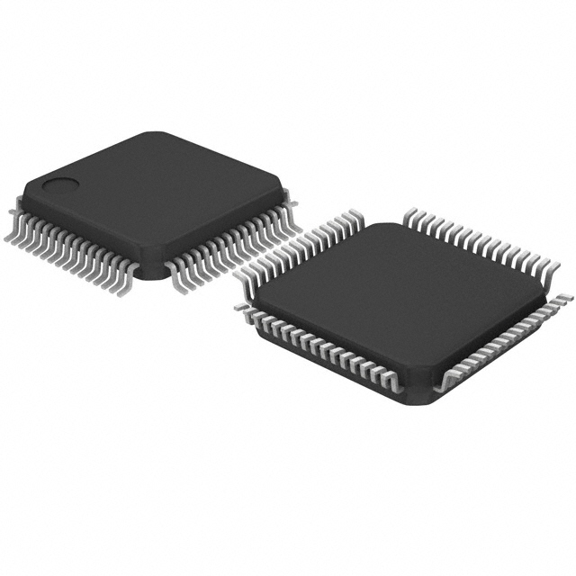
- Part No.:
- CY7C4225V-15ASC
- Manufacturer:
- Infineon Technologies
- Category:
- FIFOs Memory
- Package:
- 64-LQFP
- Datasheet:
-
 CY7C4225V-15ASC.pdf
- Description:
- IC FIFO SYNC 1KX18 11NS 64TQFP
- Quantity:
- Payment:

- Shipping:

Inventory:3,406
Please send an inquiry. Send us your inquiry, and we will respond immediately.
Product details
Overview
CY7C4225V-15ASC from Cypress Semiconductor is a 1K × 18-bit (1,024 words × 18-bit) low-voltage synchronous FIFO memory IC with 3.3 V operation, 67 MHz max clock frequency, 15 ns read/write cycle time, and 5 V-tolerant inputs. It serves as a high-speed data buffer in asynchronous interface bridging between mismatched clock domains, such as in PCI-to-PCIe bridge subsystems or DSP-to-FPGA data pipelines.
For engineers reviewing the CY7C4225V-15ASC datasheet, CY7C4225V-15ASC pinout, CY7C4225V-15ASC application, or CY7C4225V-15ASC equivalent, key selection criteria include programmable Almost Full/Almost Empty flag offsets, dual-clock asynchronous read/write capability, depth/width expansion support, and synchronous flag timing behavior dependent on SMODE pin configuration.
Technical Context
The CY7C4225V-15ASC implements a dual-port SRAM-based FIFO architecture with independent write pointer (driven by WCLK/WEN) and read pointer (driven by RCLK/REN), enabling true simultaneous read/write operations. Its status flags-EF, FF, HF, PAE, PAF-are decoded from pointer positions and updated synchronously to respective clocks (RCLK for EF/PAE, WCLK for FF/PAF) when VCC/SMODE = VSS.
It supports retransmit (RT) functionality via FL/RT pin for packet-level data recovery, and depth expansion using WXI/WXO/RXI/RXO cascade pins with FL pin strapping logic. The device uses 0.65 µm CMOS process, features 30 mA ICC at 67 MHz, and provides three-state outputs controlled by OE.
Key Specifications
| Parameter | Value and Actual Design Meaning |
|---|---|
| Memory Depth | 1,024 words - defines maximum burst-length buffering capacity before overflow occurs. |
| Data Width | 18 bits - supports parallel transfer of two 9-bit control/data words or one 16-bit word plus parity. |
| Max Clock Frequency | 67 MHz - enables 14.9 ns minimum cycle time, suitable for high-throughput serial link interfaces. |
| Read/Write Cycle Time | 15 ns - guarantees deterministic latency for real-time buffering in video frame capture pipelines. |
| Supply Voltage | 3.3 V ± 0.3 V - ensures compatibility with LVCMOS I/O standards and reduces dynamic power vs. 5 V FIFOs. |
| Input Tolerance | 5 V tolerant - allows direct connection to legacy 5 V logic without level-shifting circuitry. |
| Power Consumption | 30 mA ICC - translates to ~99 mW typical active power, critical for thermally constrained embedded modules. |
Pinout & Package
Package: 64-pin STQFP (10 mm × 10 mm, 0.5 mm pitch), RoHS-compliant, surface-mount.
| Pin/Terminal | Circuit Role | Design Meaning |
|---|---|---|
| D0–D17 | Parallel Data Input Bus | 18-bit wide input path for write data; latched on rising WCLK edge when WEN = LOW. |
| Q0–Q17 | Parallel Data Output Bus | 18-bit wide output path; driven only when OE = LOW and REN = LOW, synchronized to RCLK. |
| WCLK / RCLK | Independent Clock Inputs | Asynchronous clock domains: WCLK controls write pointer advancement; RCLK controls read pointer and EF flag update. |
| WEN / REN | Enable Controls | Active-LOW enables; must meet tENS setup/hold relative to respective clock edges for valid access. |
| EF / FF / PAF / PAE / WXO/HF | Status & Expansion Signals | EF/FF are synchronous flags; PAF/PAE configurable sync/asynchronous; WXO/HF multiplexes Half Full flag or depth-expansion output. |
| FL/RT / SMODE / RS / OE | Control Configuration Pins | FL/RT selects retransmit or first-load mode; SMODE configures flag synchronization; RS resets pointers; OE enables Q-bus tristate. |
Key Features
| Feature | Design Value |
|---|---|
| Programmable Almost Full/Empty Flags | 12-bit offset registers allow precise threshold setting (e.g., trigger PAF at 90% full) for adaptive flow control in variable-rate systems. |
| Retransmit Function | FL/RT pin enables hardware-initiated read-pointer reset to FIFO start address, supporting reliable packet retransmission without CPU intervention. |
| Depth & Width Expansion | Cascade pins (WXI/WXO/RXI/RXO) and FL strapping enable seamless stacking of multiple CY7C4225V units to achieve >1K depth or >18-bit width without external logic. |
| Synchronous Flag Architecture | EF/FF updated exclusively on RCLK/WCLK edges respectively, eliminating metastability risk in clock-domain crossing verification. |
| 5 V-Tolerant Inputs | VIH(MAX) = 5 V allows direct interfacing with mixed-voltage systems (e.g., 3.3 V FIFO + 5 V microcontroller bus), reducing BOM count. |
Applications
| High-Speed Data Acquisition | Multi-Processor Interconnect |
|---|---|
|
Use Scenario: Capturing real-time sensor streams (e.g., 12-bit ADC samples at 50 MSPS) into FPGA-based preprocessing pipeline. IC Role / Device Role / Timing Role: Serves as elastic buffer absorbing jitter between ADC sampling clock and FPGA processing clock domain. Use Value: 15 ns cycle time and 67 MHz operation prevent sample loss during burst transfers; programmable PAF triggers DMA fetch before FIFO underflow. |
Use Scenario: Arbitrating data exchange between two ARM cores running at different frequencies in an SoC test platform. IC Role / Device Role / Timing Role: Acts as decoupling FIFO between AXI masters, isolating write bursts from read latency spikes. Use Value: Independent WCLK/RCLK domains eliminate handshake logic; EF/FF flags provide ready/valid signaling without software polling. |
| Communications Protocol Bridging | Video Frame Buffering |
|
Use Scenario: Converting UART-based telemetry packets (variable length, 115.2 kbps) to fixed-width SPI frames for RF transceiver input. IC Role / Device Role / Timing Role: Buffers incoming byte stream and aligns payload into 18-bit words for downstream serializer. Use Value: Retransmit (RT) function enables packet resend on CRC failure; 5 V-tolerant D-inputs accept legacy UART voltage levels directly. |
Use Scenario: Storing progressive-scan YUV422 video lines (1,920 pixels × 16 bits) during format conversion in broadcast encoder. IC Role / Device Role / Timing Role: Provides line-level buffering between pixel clock (74.25 MHz) and system bus clock (100 MHz). Use Value: 1K × 18 capacity holds one full HD line; Half Full (HF) flag signals mid-line readiness for DMA transfer to SDRAM. |
Equivalent & Alternatives
The following parts are listed as comparable options for similar FIFO memory applications.
| Alternative Part | Technical Difference | Application Difference | Selection Advice |
|---|---|---|---|
| IDT72V2113L15PF | 1K × 18, 3.3 V, 15 ns cycle, but lacks retransmit and SMODE-configurable flag sync; uses different pinout. | No hardware retransmit support; requires external logic for packet recovery; flag timing fixed to clock edges. | Choose when retransmit is unnecessary and PCB layout prioritizes pin compatibility with IDT footprint. |
| ON Semiconductor NB3N502M | 1K × 18, 3.3 V, but is a clock generator with integrated FIFO-not a standalone FIFO; no WCLK/RCLK independence. | Designed for clock distribution with embedded buffering, not general-purpose data staging. | Choose only if system requires jitter-clean clock synthesis alongside minimal buffering, not pure FIFO functionality. |
Compared with IDT72V2113L15PF and NB3N502M, the CY7C4225V-15ASC uniquely combines programmable flag thresholds, hardware retransmit, and true dual-clock domain isolation-making it optimal for protocol-aware, high-reliability buffering where deterministic latency and recovery autonomy are required.
Availability
CY7C4225V-15ASC is available at Aetrix Electronics and suitable for high-speed data acquisition systems, multi-processor interconnects, and communications protocol bridging requiring stable component supply across extended production lifecycles.
Supply support for CY7C4225V-15ASC includes scheduled delivery planning, volume procurement assistance, BOM continuity management, traceable sourcing, and lifecycle availability coordination for OEM customers, industrial embedded developers, connected-device designers, and electronics production programs.
Manufacturer
Cypress Semiconductor (now part of Infineon Technologies) designs high-performance mixed-signal ICs for embedded control, connectivity, and memory applications, with focus on reliability and integration.
The CY7C42X5V family was developed specifically for high-speed, low-latency data buffering in clock-domain-crossing scenarios-targeting telecom infrastructure, test equipment, and real-time imaging systems.
FAQ
What is the default Almost Empty offset value for CY7C4225V-15ASC?
The default Almost Empty offset is 127 words. This means the PAE flag asserts when 127 or fewer words remain in the FIFO. The offset can be reprogrammed via the LD/WEN/WCLK sequence to values between 0 and 255, allowing fine-grained flow control tuning for specific data rate mismatches.
How does the SMODE pin affect flag timing behavior?
When VCC/SMODE is tied to VSS, PAE and PAF become synchronous to RCLK and WCLK respectively-ensuring glitch-free flag transitions aligned to clock edges. When tied to VCC, they operate asynchronously, which may simplify timing closure in some legacy designs but introduces metastability risk in high-speed clock-domain crossings.
Can CY7C4225V-15ASC be used in single-clock mode?
Yes. WCLK and RCLK pins may be connected together for single-clock operation. In this configuration, the FIFO behaves as a synchronous FIFO with all timing referenced to one clock, simplifying PCB routing and timing analysis-but sacrificing the ability to absorb sustained read/write rate mismatches over long durations.
What is the purpose of the FL/RT pin in standalone mode?
In standalone mode (not cascaded), FL/RT functions as Retransmit (RT). A HIGH pulse on this pin resets the internal read pointer to the FIFO's first location, enabling hardware-triggered replay of buffered data-critical for packetized protocols where acknowledgment and retry are handled at the physical layer without CPU involvement.
CY7C4225V-15ASC Specifications
- Product attributes
- Attribute value
- Manufacturer:
- Infineon Technologies
- Series:
- CY7C
- Package/Case:
- 64-LQFP
- Packaging:
- Bag
- Product Status:
- Obsolete
- Programmable:
- Not Verified
- Memory Size:
- 18K (1K x 18)
- Function:
- Synchronous
- Data Rate:
- 66.7MHz
- Access Time:
- 11ns
- Voltage - Supply:
- 3 V ~ 3.6 V
- Current - Supply (Max):
- 30mA
- Bus Directional:
- Uni-Directional
- Expansion Type:
- Depth, Width
- Programmable Flags Support:
- Yes
- Retransmit Capability:
- Yes
- FWFT Support:
- No
- Operating Temperature:
- 0°C ~ 70°C
- Mounting Type:
- Surface Mount
- Supplier Device Package:
- 64-TQFP (10x10)
CY7C4225V-15ASC FAQ
1.How can I place an order for CY7C4225V-15ASC through Aetrix?
Please submit a Request for Quotation (RFQ) for CY7C4225V-15ASC on Aetrix. Our sales agent will provide a competitive quotation and guide you through the order confirmation once you accept the terms.
2.Are the price and stock information for CY7C4225V-15ASC reliable?
The price and inventory of CY7C4225V-15ASC are updated periodically and may fluctuate due to market conditions. Stock and pricing data are typically refreshed every 24 hours. Quotation validity for CY7C4225V-15ASC is usually 5 days.
3.What payment methods are accepted for CY7C4225V-15ASC?
We accept Wire Transfer, PayPal, Credit Card, Western Union, MoneyGram, and Escrow for CY7C4225V-15ASC transactions.
Note: Certain payment methods may incur a processing fee.
4.How is shipping managed for CY7C4225V-15ASC?
CY7C4225V-15ASC orders can be shipped via leading logistics carriers, including DHL, UPS, FedEx, TNT, or Registered Mail.
Once your CY7C4225V-15ASC order is processed, you will receive an email with the shipment details and tracking number.
Note: Tracking information may take up to 24 hours to appear. Express delivery typically takes 3–5 business days.
5.How can I obtain technical support or documentation for CY7C4225V-15ASC?
For technical support, including CY7C4225V-15ASC datasheets, pinout diagrams, or application guidance, please contact our engineering support team. They can provide detailed documentation and assistance for your CY7C4225V-15ASC requirements.
6.How does Aetrix verify that CY7C4225V-15ASC is sourced from the original manufacturer or authorized distributors?
All CY7C4225V-15ASC products on Aetrix are procured from qualified distributors and authorized channels. Our dedicated quality assurance team conducts strict verification, including traceability checks and, if necessary, third-party testing. This ensures that CY7C4225V-15ASC meets industry standards.
7.What is the process for return or replacement of CY7C4225V-15ASC?
All CY7C4225V-15ASC units undergo pre-shipment inspection (PSI). If there is an issue with CY7C4225V-15ASC, returns or replacements are accepted under the following conditions:
1.Quantity discrepancies, incorrect items, or visible external defects (such as breakage or corrosion), acknowledged by Aetrix.
2.The issue is reported within 90 days of delivery.
3.The CY7C4225V-15ASC part is unused and in its original packaging.
Return procedure for CY7C4225V-15ASC:
1.Submit a request within 90 days.
2.Obtain a Return Material Authorization (RMA) from Aetrix.
CY7C4225V-15ASC Tags
-
7201LA15JGI
Renesas Electronics Corporation
-
7204L12JG
Renesas Electronics Corporation

-
72V82L15PAG8
Renesas Electronics Corporation

-
7205L15JGI
Renesas Electronics Corporation
-
7208L20JG
Renesas Electronics Corporation

-
72V2105L10PFG
Renesas Electronics Corporation
-
72V2111L15PFGI
Renesas Electronics Corporation

-
72V2113L6PFG
Renesas Electronics Corporation
-
72V36110L6PFG
Renesas Electronics Corporation

-
SN74ALVC7804-40DL
Texas Instruments
-
7202LA25JGI
Renesas Electronics Corporation
-
SN74V245-15PAG
Texas Instruments
Tech Hub

An engineering guide to LED driver operation, constant-current and constant-voltage outputs, linear and switching topologies, dimming, IC selection, calculations, replacement compatibility, and fault c…

Operational amplifier guide covering op amp basics, feedback, ideal vs real op amps, common configurations, buffer circuits, offset, bias current, gain-bandwidth, slew rate, rail-to-rail limits and sel…

Jumper cables guide covering safe connection order, red and black clamp placement, final ground connection, cable gauge, length, clamp quality, copper vs CCA cables, jump starter comparison and battery…

LDO regulator guide covering low dropout voltage, power dissipation, thermal design, PSRR, output noise, capacitor stability, adjustable LDO circuits, LDO vs buck converter and datasheet selection chec…

Conditional Access Module guide covering CAM meaning, CI/CI+ interface, smart card authorization, DVB security workflow, TV and set-top box compatibility, internal electronics, ESD protection, connecto…

Guide to electronic component obsolescence covering EOL risk, PCN/PDN notices, last-time buy planning, replacement options, form-fit-function validation, counterfeit risk and BOM lifecycle management.

18650 battery guide covering lithium-ion cell basics, 3.6V/3.7V voltage, 4.2V charging, mAh and Wh capacity, protected cells, chargers, BMS, series-parallel packs, holders, welding and sourcing checks.…

Hall effect sensor guide covering working principle, linear and digital sensors, Arduino circuits, current sensing, speed detection, automotive applications, A3144 examples, signal filtering and datash…

Product Change Notification guide for electronic components, covering PCN meaning, PCN vs PDN/EOL, common change types, risk levels, form-fit-function review, engineering validation, BOM control, LTB/L…

A practical guide to blend door actuators, covering HVAC function, symptoms, location, AC and heater issues, reset and calibration, replacement cost, electrical diagnosis, compatibility checks, and rep…


