
 My Inquiry
 My Account


Renesas D13002F10V
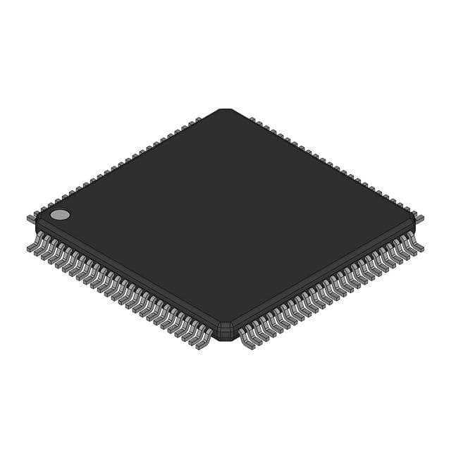
- Part No.:
- D13002F10V
- Manufacturer:
- Renesas
- Category:
- Microcontrollers
- Package:
- -
- Datasheet:
-
 D13002F10V.pdf
- Description:
- MCU H8/300H / H8/3002
- Quantity:
- Payment:

- Shipping:

Inventory:421
Please send an inquiry. Send us your inquiry, and we will respond immediately.
Product details
Overview
D13002F10V from Fairchild Semiconductor is an NPN triple-diffused planar silicon transistor designed for high-voltage horizontal deflection in color display systems, featuring VCBO = 1550 V, VCEO = 750 V, IC = 10 A (DC), PC = 60 W, and tF = 0.2 µs (max) for fast switching in CRT monitor output stages.
For engineers reviewing the D13002F10V datasheet, D13002F10V pinout, D13002F10V application, or D13002F10V equivalent, key selection criteria include high-voltage blocking capability, pulse current handling up to 20 A, thermal resistance of 2.08 °C/W, saturation voltage under 3 V at 6 A, and TO-3PF package compatibility with heatsink mounting in legacy display power circuits.
Technical Context
This transistor operates as a high-voltage switch in horizontal deflection yoke drive circuits, where rapid turn-off (tF ≤ 0.2 µs) and low storage time (tSTG ≤ 3 µs) minimize retrace distortion. It sustains repetitive 200 V collector pulses with 6 A load current and reverse base drive (–2.4 A) for controlled commutation.
Its rugged triple-diffused structure supports safe operating area (SOA) compliance up to 1000 V × 10 A in single-pulse mode, with junction temperature rated to 150 °C and storage range from –55 °C to +150 °C - critical for thermally demanding CRT flyback environments.
Key Specifications
| Parameter | Value and Actual Design Meaning |
|---|---|
| VCBO | 1550 V - Withstands 1.55 kV between collector and base, enabling direct use in 110–240 VAC-fed horizontal deflection circuits without external snubbing. |
| VCEO | 750 V - Sustains 750 V collector-emitter during flyback recovery, matching typical CRT line scan voltage peaks. |
| IC (DC) | 10 A - Supports continuous horizontal output current for 19–21 inch color monitors with standard yoke impedance. |
| tF | 0.2 µs (max) - Ensures sub-microsecond fall time to limit retrace time and reduce horizontal linearity error. |
| RθjC | 2.08 °C/W - Enables effective heat transfer to heatsink; allows 60 W dissipation with ≤125 °C case rise above ambient. |
| VCE(sat) | 3 V @ IC=6 A, IB=1.5 A - Limits conduction loss to <18 W during active scan, preserving efficiency in linearly driven yoke circuits. |
| hFE | 5–10 @ IC=6 A - Provides predictable base drive requirement (1.5 A) for stable switching in fixed-gain driver topologies. |
Pinout & Package
Supplied in TO-3PF metal can package with isolated tab, featuring integral mounting hole and standardized 15.5 mm × 26.5 mm footprint for mechanical compatibility with legacy CRT chassis heatsinks.
| Pin/Terminal | Circuit Role | Design Meaning |
|---|---|---|
| 1 (Base) | Control input | Receives forward base current (up to 1.5 A) and reverse base current (–2.4 A) to actively control turn-on/turn-off timing. |
| 2 (Collector) | High-voltage power node | Connects to flyback transformer primary and horizontal yoke; rated for 1550 V C-B and 750 V C-E breakdown. |
| 3 (Emitter) | Power return path | Serves as low-side reference for deflection current loop; tied to ground or damper diode cathode in standard configurations. |
Key Features
| Feature | Design Value |
|---|---|
| High-Voltage Blocking | VCBO = 1550 V enables direct integration into 20–25 kV flyback-derived horizontal supply rails without cascading devices. |
| Fast Switching | tF ≤ 0.2 µs and tSTG ≤ 3 µs support 15.734 kHz horizontal scanning with minimal trace distortion. |
| Rugged SOA | Forward bias SOA covers 750 V × 10 A (DC) and 1000 V × 6 A (pulse), ensuring reliability under transient overloads. |
| Thermal Robustness | Junction-to-case thermal resistance of 2.08 °C/W allows sustained 60 W operation with standard finned heatsinks in enclosed chassis. |
Applications
| Color CRT Monitor Horizontal Deflection | High-Voltage Flyback Driver |
|---|---|
Use Scenario: Driving horizontal deflection yoke in 19–21 inch color CRT monitors with 15.734 kHz line frequency and 50–60 µs retrace interval. IC Role / Device Role / Timing Role: Primary switching transistor in quasi-resonant horizontal output stage, conducting during trace and commutating during retrace. Use Value: Delivers precise timing control with tF ≤ 0.2 µs and tSTG ≤ 3 µs, minimizing horizontal linearity error and geometry distortion. | Use Scenario: Acting as main switch in flyback converter powering CRT EHT and filament supplies in analog display systems. IC Role / Device Role / Timing Role: High-voltage power switch synchronizing with horizontal sync signal to generate regulated high-voltage outputs. Use Value: Withstands 1550 V VCBO and handles 20 A pulsed collector current, supporting reliable energy transfer across wide input voltage ranges. |
| Legacy Display Repair Replacement | Industrial HV Pulse Generator |
Use Scenario: Drop-in replacement for obsolete horizontal output transistors (e.g., BU2520DX, 2SC5148) in service centers repairing aging CRT equipment. IC Role / Device Role / Timing Role: Direct-fit mechanical and electrical substitute maintaining original PCB layout and driver circuit compatibility. Use Value: TO-3PF package and identical pinout (B-C-E) enable zero-modification board-level replacement with verified VCEO/IC margin. | Use Scenario: Generating controlled high-voltage pulses (≤750 V, ≤10 A) in industrial test equipment, laser drivers, or plasma ignition modules. IC Role / Device Role / Timing Role: Fast-switching power switch triggered by TTL-compatible base drive in repetitive pulse applications. Use Value: Confirmed tF ≤ 0.2 µs and RθjC = 2.08 °C/W support 100 Hz–1 kHz pulse repetition with stable thermal performance. |
Equivalent & Alternatives
The following parts are listed as comparable options for similar high-voltage switching transistor applications.
| Alternative Part | Technical Difference | Application Difference | Selection Advice |
|---|---|---|---|
| BU2520DX | VCEO = 1500 V, IC = 10 A, tF = 0.3 µs, TO-3P package | Higher VCEO but slower switching; requires larger heatsink due to higher RθjC. | Preferred where absolute maximum VCEO margin is prioritized over retrace fidelity. |
| 2SC5148 | VCBO = 1500 V, IC = 8 A, tF = 0.15 µs, TO-3PF package | Lower IC rating and narrower SOA; not rated for 20 A pulse current. | Suitable only in lower-power CRT designs or where base drive is limited to ≤1.2 A. |
Compared with BU2520DX and 2SC5148, the D13002F10V offers optimal balance of 1550 V VCBO, 750 V VCEO, 20 A pulse capability, and 0.2 µs tF - making it the most suitable choice for modern CRT repair and high-fidelity horizontal deflection where both voltage headroom and switching speed are critical.
Availability
D13002F10V is available at Aetrix Electronics and suitable for CRT monitor repair, industrial high-voltage pulse generation, and legacy display system maintenance requiring stable component supply and long-term obsolescence mitigation.
Supply support for D13002F10V includes scheduled delivery planning, volume procurement assistance, BOM continuity management, traceable sourcing, and lifecycle availability coordination for OEM customers, industrial embedded developers, connected-device designers, and electronics production programs.
Manufacturer
Fairchild Semiconductor was a U.S.-based semiconductor company specializing in power discrete devices, analog ICs, and interface solutions before its acquisition by ON Semiconductor in 2016.
The D13002F10V belongs to Fairchild's high-voltage horizontal deflection transistor product line, engineered specifically for reliability and timing precision in analog CRT display output stages.
FAQ
What is the maximum collector-emitter voltage rating for D13002F10V?
The D13002F10V has a maximum collector-emitter voltage (VCEO) rating of 750 V at TC = 25 °C. This rating applies under DC conditions and defines the upper limit for safe operation in horizontal deflection circuits where flyback voltage peaks occur. Exceeding this voltage risks avalanche breakdown and permanent device failure. The D13002F10V must be used with appropriate snubber networks and voltage clamping when deployed in systems approaching this limit.
Does D13002F10V support pulse current operation beyond its DC rating?
Yes, the D13002F10V supports pulsed collector current up to 20 A (ICP), specified under pulse test conditions of 5 ms width and duty cycle < 10%. This capability enables robust performance during horizontal trace intervals in CRT applications where peak currents exceed the 10 A DC rating. Thermal design must account for RMS current and duty cycle to avoid junction overheating, especially given the device's 2.08 °C/W RθjC.
What is the pin configuration of D13002F10V and how is it mounted?
The D13002F10V uses a TO-3PF package with pinout Base–Collector–Emitter (1–2–3) when viewed from the front with leads down and tab facing outward. The metal case is electrically isolated from the collector, allowing direct heatsink mounting without insulating washers. Mounting torque must not exceed 1.0 N·m to prevent package deformation, and thermal compound should be applied evenly to ensure RθjC remains at 2.08 °C/W as specified.
Can D13002F10V replace BU2520DX in existing CRT designs?
Yes, the D13002F10V is a functional and mechanical replacement for BU2520DX in most CRT horizontal output stages. Both share TO-3PF packaging, B–C–E pinout, and 10 A DC collector current rating. However, the D13002F10V offers higher VCBO (1550 V vs. 1500 V) and faster tF (0.2 µs vs. 0.3 µs), improving retrace performance. Verify base drive capability matches the D13002F10V's 1.5 A requirement before substitution.
What thermal derating applies to D13002F10V above 25°C case temperature?
The D13002F10V's collector power dissipation (PC) must be linearly derated above 25 °C case temperature at 0.48 W/°C, based on its 2.08 °C/W RθjC and 150 °C maximum junction temperature. At TC = 100 °C, maximum allowable PC drops to approximately 36 W. This derating curve is defined in Figure 11 of the datasheet and must be applied in enclosed or high-ambient environments to prevent thermal runaway.
D13002F10V Specifications
- Product attributes
- Attribute value
- Manufacturer:
- Renesas
- Package/Case:
- -
- Series:
- H8® H8/300H
- Packaging:
- Bulk
- Product Status:
- Active
- Programmable:
- Not Verified
- Core Processor:
- H8/300H
- Core Size:
- 16-Bit
- Speed:
- 10MHz
- Connectivity:
- SCI
- Peripherals:
- -
- Number of I/O:
- -
- Program Memory Size:
- -
- Program Memory Type:
- ROMless
- EEPROM Size:
- -
- RAM Size:
- 512 x 8
- Voltage - Supply (Vcc/Vdd):
- 2.7V ~ 5.5V
- Data Converters:
- A/D 8x10b
- Oscillator Type:
- Internal
- Operating Temperature:
- -20°C ~ 75°C (TA)
- Grade:
- -
- Qualification:
- -
- Mounting Type:
- -
- Supplier Device Package:
D13002F10V FAQ
1.How can I place an order for D13002F10V through Aetrix?
Please submit a Request for Quotation (RFQ) for D13002F10V on Aetrix. Our sales agent will provide a competitive quotation and guide you through the order confirmation once you accept the terms.
2.Are the price and stock information for D13002F10V reliable?
The price and inventory of D13002F10V are updated periodically and may fluctuate due to market conditions. Stock and pricing data are typically refreshed every 24 hours. Quotation validity for D13002F10V is usually 5 days.
3.What payment methods are accepted for D13002F10V?
We accept Wire Transfer, PayPal, Credit Card, Western Union, MoneyGram, and Escrow for D13002F10V transactions.
Note: Certain payment methods may incur a processing fee.
4.How is shipping managed for D13002F10V?
D13002F10V orders can be shipped via leading logistics carriers, including DHL, UPS, FedEx, TNT, or Registered Mail.
Once your D13002F10V order is processed, you will receive an email with the shipment details and tracking number.
Note: Tracking information may take up to 24 hours to appear. Express delivery typically takes 3–5 business days.
5.How can I obtain technical support or documentation for D13002F10V?
For technical support, including D13002F10V datasheets, pinout diagrams, or application guidance, please contact our engineering support team. They can provide detailed documentation and assistance for your D13002F10V requirements.
6.How does Aetrix verify that D13002F10V is sourced from the original manufacturer or authorized distributors?
All D13002F10V products on Aetrix are procured from qualified distributors and authorized channels. Our dedicated quality assurance team conducts strict verification, including traceability checks and, if necessary, third-party testing. This ensures that D13002F10V meets industry standards.
7.What is the process for return or replacement of D13002F10V?
All D13002F10V units undergo pre-shipment inspection (PSI). If there is an issue with D13002F10V, returns or replacements are accepted under the following conditions:
1.Quantity discrepancies, incorrect items, or visible external defects (such as breakage or corrosion), acknowledged by Aetrix.
2.The issue is reported within 90 days of delivery.
3.The D13002F10V part is unused and in its original packaging.
Return procedure for D13002F10V:
1.Submit a request within 90 days.
2.Obtain a Return Material Authorization (RMA) from Aetrix.
D13002F10V Tags

-
ATTINY4-TSHR
Microchip Technology
-
ATTINY10-TSHR
Microchip Technology
-
ATTINY10-TS8R
Microchip Technology

-
ATTINY202-SSNR
Microchip Technology
-
ATTINY202-SSFR
Microchip Technology
-
ATTINY402-SSNR
Microchip Technology

-
PIC16F15213T-I/MF
Microchip Technology
-
PIC16F15213-E/MF
Microchip Technology

-
PIC10F200T-I/OT
Microchip Technology
-
ATTINY412-SSNR
Microchip Technology
-
PIC10F202T-I/OT
Microchip Technology

-
ATTINY404-SSNR
Microchip Technology
Tech Hub

TTL and CMOS logic families differ in thresholds, loading, output drive, power and timing. This engineering guide compares 74HC and 74HCT, calculates noise margins and checks 3.3 V/5 V compatibility.

A practical engineering guide to 3.3V and 5V logic compatibility, input thresholds, resistor dividers, translator ICs, MOSFET level shifting, I2C pull-ups, timing limits and power-sequencing risks.

The 74HC595 uses push-pull logic outputs, while the TPIC6B595 uses 50 V open-drain DMOS sinks for higher-power loads. This guide compares timing, current limits, 3.3 V interfacing, load wiring, thermal…

The 74HC595 converts serial data into eight stable parallel outputs. This guide covers pin functions, shift and storage timing, OE and MR behavior, drive-current limits, cascading, voltage compatibilit…

A technical comparison of level-sensitive latches and edge-triggered flip-flops, covering timing windows, setup and hold limits, master–slave operation, time borrowing, race-through, HDL inference and…

A D latch stores one bit while Enable controls when data can pass. This reference covers gate-level operation, truth tables, transparency, setup and hold timing, LE versus OE, common ICs and practical …

An SR latch stores one bit through cross-coupled feedback. This engineering reference covers NOR and NAND implementations, truth tables, forbidden-state recovery, gated operation, switch debouncing, fa…

Latch circuits retain one bit through feedback. This technical reference covers SR and D latches, truth tables, transparency, timing limits, latch-versus-flip-flop behavior, applications and common log…

An engineering guide to LED driver operation, constant-current and constant-voltage outputs, linear and switching topologies, dimming, IC selection, calculations, replacement compatibility, and fault c…

Operational amplifier guide covering op amp basics, feedback, ideal vs real op amps, common configurations, buffer circuits, offset, bias current, gain-bandwidth, slew rate, rail-to-rail limits and sel…


