
 My Inquiry
 My Account


Analog Devices Inc. DC112A-B
- Part No.:
- DC112A-B
- Manufacturer:
- Analog Devices Inc.
- Category:
- Sensor Evaluation Boards
- Package:
- Datasheet:
-
 DC112A-B.pdf
- Description:
- LT1328CMS8 - IR TRANSCEIVER - IR
- Quantity:
- Payment:

- Shipping:

Inventory:3,481
Please send an inquiry. Send us your inquiry, and we will respond immediately.
Product details
Overview
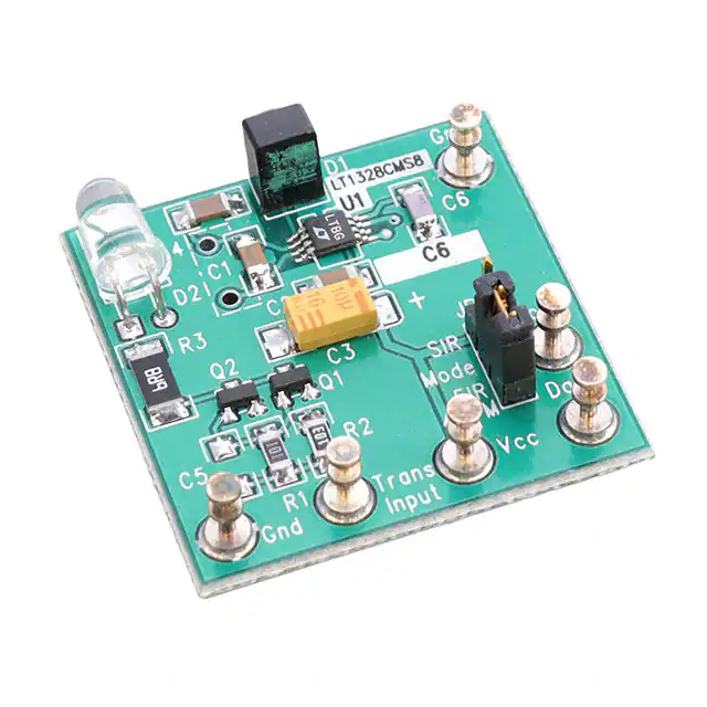
DC112A-B from Analog Devices (formerly Linear Technology) is an IrDA-compliant demonstration board implementing a complete infrared transmitter/receiver system based on the LT1328 photodiode receiver IC. It supports SIR (up to 115 kbaud), FIR (1.15 Mbaud), and 4PPM (4 Mbps) data links, features configurable MODE jumper for data-rate selection, TTL-level DATA output (Pin 5 of LT1328), and onboard HSDL-4220 LED transmitter with BPV22NF photodiode receiver.
For engineers reviewing the DC112A-B datasheet, DC112A-B pinout, DC112A-B application, or DC112A-B equivalent, this evaluation board enables rapid validation of IrDA physical-layer performance-including pulse fidelity, range testing at 1 cm and 1 m, interference rejection under ambient light, and modulation-specific timing compliance for serial infrared, fast infrared, and 4 MHz pulse-position modulation systems.
Technical Context
The DC112A-B implements dual-path signal conditioning: the LT1328 receiver uses a transimpedance preamp, high-pass servo filter (pole set by C4 = 330 pF for >200 kHz passband), and comparator with TTL output logic-where HIGH = no light, LOW = detected pulse. The MODE pin (LT1328 Pin 7) selects between SIR (MODE = VCC, adds C1 in parallel with C4) and FIR/4PPM (MODE = GND).
Transmitter functionality is discrete: Q1/Q2 2N7002 MOSFETs drive the HSDL-4220 LED via R3 (6.3 Ω), with input compatibility to 5 V TTL logic. Power is supplied via single 5 V rail; quiescent current draw is dominated by LT1328's 2 mA and LED bias during transmission.
Key Specifications
| Parameter | Value and Actual Design Meaning |
|---|---|
| Supported Protocols | IrDA-SIR (2.4–115 kbaud), IrDA-FIR (1.15 Mbaud), 4PPM (4 Mbps) |
| Receiver IC | LT1328CS8: SO-8 packaged photodiode receiver with integrated preamp, servo filter, and comparator |
| Data Output Logic | TTL-compatible: HIGH = no incident light; LOW = valid IR pulse detection |
| Filter Configuration | Selectable high-pass cutoff: ~200 kHz (FIR/4PPM) or lower (SIR) via MODE jumper and C1/C4 network |
| Photodiode | BPV22NF silicon PIN diode optimized for 850 nm IR, 1 ns rise time, 1 nA dark current |
| LED Transmitter | HSDL-4220 GaAs IR emitter, 850 nm peak, 20° half-angle, 100 mA pulsed drive capability |
| Power Supply | Single 5 V ±5%, capable of delivering ≥25 mA for full operation including LED pulses |
Availability
DC112A-B is available at Aetrix Electronics and suitable for IrDA protocol validation, optical link range testing, ambient light interference evaluation, and embedded infrared interface development requiring stable component supply and documented reference design implementation.
Supply support for DC112A-B includes scheduled delivery planning, volume procurement assistance, BOM continuity management, traceable sourcing, and lifecycle availability coordination for OEM customers, industrial embedded developers, connected-device designers, and electronics production programs.
Manufacturer
Analog Devices acquired Linear Technology in 2017; Linear originally designed and qualified the DC112A-B as part of its precision analog and interface demonstration platform family.
The DC112A-B belongs to Linear's legacy demonstration board product line, engineered specifically to accelerate prototyping and characterization of IrDA-compliant infrared data links using the LT1328 receiver and discrete LED driver architecture.
FAQ
What is the function of the MODE jumper on the DC112A-B?
The MODE jumper on the DC112A-B configures the LT1328's internal servo filter pole: when set to SIR, it connects Pin 7 (MODE) to VCC, enabling C1 (10 nF) in parallel with C4 (330 pF) to lower the high-pass cutoff for slower data rates; when set to FIR/4PPM, MODE is grounded, yielding a higher cutoff (~200 kHz) required for 1.15 Mbaud and 4 Mbps operation. This setting directly determines which IrDA modulation scheme the DC112A-B will correctly demodulate.
Can the DC112A-B operate with a 3.3 V supply instead of 5 V?
No - the DC112A-B is designed for 5 V operation only. The LT1328CS8 requires a minimum 4.5 V supply per its datasheet, and the HSDL-4220 LED driver circuit (Q1/Q2 + R3) is biased for 5 V TTL logic levels and 100 mA peak current. Using 3.3 V would result in insufficient LED drive, degraded signal-to-noise ratio at the photodiode, and failure to meet IrDA timing specifications. The DC112A-B does not include level-shifting or voltage regulation for alternate supplies.
How is the DATA output of the DC112A-B electrically defined?
The DATA output (E4 on the DC112A-B board, corresponding to Pin 5 of the LT1328CS8) provides a TTL-compatible digital signal: logic HIGH (≥2.4 V) indicates absence of detected IR light; logic LOW (≤0.8 V) indicates successful detection of a valid IR pulse. This active-low behavior matches IrDA physical layer expectations, and the output drives standard TTL loads without buffering. Rise/fall times are <20 ns, verified in Figures 3–5 of the DC112A-B demo manual.
Does the DC112A-B include ESD protection for the photodiode or LED inputs?
No explicit on-board ESD protection components (e.g., TVS diodes or polymer suppressors) are shown in the DC112A-B schematic or parts list. The BPV22NF photodiode has inherent junction capacitance and moderate ESD tolerance (HBM ±500 V), and the HSDL-4220 LED is rated for HBM ±2 kV, but the DC112A-B layout provides no additional transient suppression. Users handling the board must observe standard ESD precautions, especially when connecting external cables or probing the IN, DATA, or MODE pins.
What oscilloscope setup is recommended to verify DC112A-B operation per Figures 3–5?
To replicate the waveforms in Figures 3–5 of the DC112A-B demo manual, use a 100 MHz+ bandwidth oscilloscope with 10× passive probes. Connect the probe ground to E1 (GND) and the signal tip to E4 (DATA). Drive the IN pin (E6) with a TTL-compatible pulse generator set to the target IrDA mode (e.g., 115 kbaud NRZ for SIR). Trigger on the IN signal, and ensure coaxial termination (50 Ω) at the generator output to preserve edge integrity. Ambient lighting must be controlled to avoid saturation of the BPV22NF photodiode during testing.
DC112A-B Specifications
- Product attributes
- Attribute value
- Manufacturer:
- Analog Devices Inc.
- Series:
- -
- Packaging:
- Bulk
- Product Status:
- Obsolete
- Sensor Type:
- Light, Infrared (IR)
- Sensing Range:
- -
- Interface:
- -
- Sensitivity:
- -
- Voltage - Supply:
- -
- Embedded:
- -
- Contents:
- Board(s)
- Utilized IC / Part:
- LT1328
DC112A-B FAQ
1.How can I place an order for DC112A-B through Aetrix?
Please submit a Request for Quotation (RFQ) for DC112A-B on Aetrix. Our sales agent will provide a competitive quotation and guide you through the order confirmation once you accept the terms.
2.Are the price and stock information for DC112A-B reliable?
The price and inventory of DC112A-B are updated periodically and may fluctuate due to market conditions. Stock and pricing data are typically refreshed every 24 hours. Quotation validity for DC112A-B is usually 5 days.
3.What payment methods are accepted for DC112A-B?
We accept Wire Transfer, PayPal, Credit Card, Western Union, MoneyGram, and Escrow for DC112A-B transactions.
Note: Certain payment methods may incur a processing fee.
4.How is shipping managed for DC112A-B?
DC112A-B orders can be shipped via leading logistics carriers, including DHL, UPS, FedEx, TNT, or Registered Mail.
Once your DC112A-B order is processed, you will receive an email with the shipment details and tracking number.
Note: Tracking information may take up to 24 hours to appear. Express delivery typically takes 3–5 business days.
5.How can I obtain technical support or documentation for DC112A-B?
For technical support, including DC112A-B datasheets, pinout diagrams, or application guidance, please contact our engineering support team. They can provide detailed documentation and assistance for your DC112A-B requirements.
6.How does Aetrix verify that DC112A-B is sourced from the original manufacturer or authorized distributors?
All DC112A-B products on Aetrix are procured from qualified distributors and authorized channels. Our dedicated quality assurance team conducts strict verification, including traceability checks and, if necessary, third-party testing. This ensures that DC112A-B meets industry standards.
7.What is the process for return or replacement of DC112A-B?
All DC112A-B units undergo pre-shipment inspection (PSI). If there is an issue with DC112A-B, returns or replacements are accepted under the following conditions:
1.Quantity discrepancies, incorrect items, or visible external defects (such as breakage or corrosion), acknowledged by Aetrix.
2.The issue is reported within 90 days of delivery.
3.The DC112A-B part is unused and in its original packaging.
Return procedure for DC112A-B:
1.Submit a request within 90 days.
2.Obtain a Return Material Authorization (RMA) from Aetrix.
DC112A-B Tags
-
1782
Adafruit Industries LLC
-
SEN0142
DFRobot

-
2857
Adafruit Industries LLC
-
3316
Adafruit Industries LLC
-
2652
Adafruit Industries LLC
-
3317
Adafruit Industries LLC
-
163
Adafruit Industries LLC
-
SEN-09269
SparkFun Electronics
-
3709
Adafruit Industries LLC
-
1018
Adafruit Industries LLC
-
VL53L5CX-SATEL
STMicroelectronics
-
3387
Adafruit Industries LLC
Tech Hub

A practical engineering guide to 3.3V and 5V logic compatibility, input thresholds, resistor dividers, translator ICs, MOSFET level shifting, I2C pull-ups, timing limits and power-sequencing risks.

The 74HC595 uses push-pull logic outputs, while the TPIC6B595 uses 50 V open-drain DMOS sinks for higher-power loads. This guide compares timing, current limits, 3.3 V interfacing, load wiring, thermal…

The 74HC595 converts serial data into eight stable parallel outputs. This guide covers pin functions, shift and storage timing, OE and MR behavior, drive-current limits, cascading, voltage compatibilit…

A technical comparison of level-sensitive latches and edge-triggered flip-flops, covering timing windows, setup and hold limits, master–slave operation, time borrowing, race-through, HDL inference and…

A D latch stores one bit while Enable controls when data can pass. This reference covers gate-level operation, truth tables, transparency, setup and hold timing, LE versus OE, common ICs and practical …

An SR latch stores one bit through cross-coupled feedback. This engineering reference covers NOR and NAND implementations, truth tables, forbidden-state recovery, gated operation, switch debouncing, fa…

Latch circuits retain one bit through feedback. This technical reference covers SR and D latches, truth tables, transparency, timing limits, latch-versus-flip-flop behavior, applications and common log…

An engineering guide to LED driver operation, constant-current and constant-voltage outputs, linear and switching topologies, dimming, IC selection, calculations, replacement compatibility, and fault c…

Operational amplifier guide covering op amp basics, feedback, ideal vs real op amps, common configurations, buffer circuits, offset, bias current, gain-bandwidth, slew rate, rail-to-rail limits and sel…

Jumper cables guide covering safe connection order, red and black clamp placement, final ground connection, cable gauge, length, clamp quality, copper vs CCA cables, jump starter comparison and battery…


