
 My Inquiry
 My Account


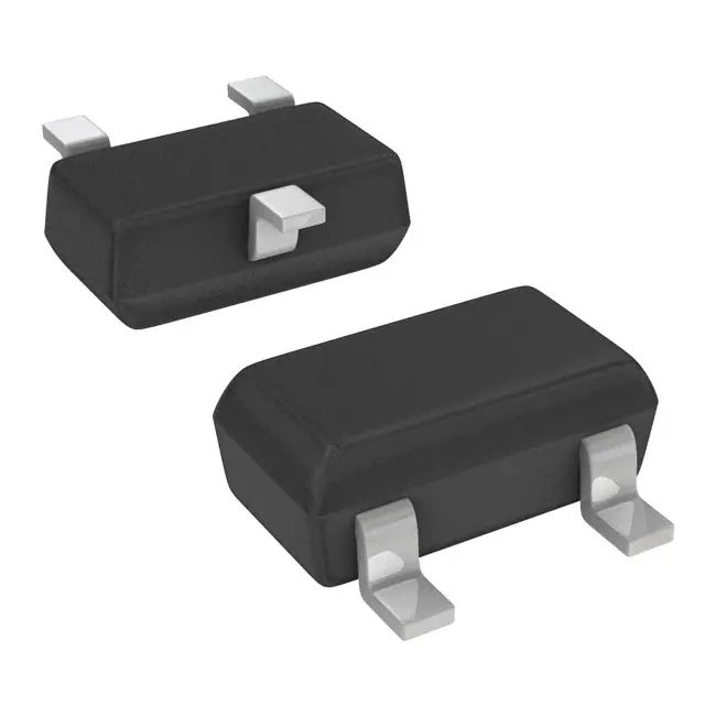
Diodes Incorporated DDTA125TKA-7-F
- Part No.:
- DDTA125TKA-7-F
- Manufacturer:
- Diodes Incorporated
- Category:
- Single, Pre-Biased Bipolar Transistors
- Package:
- TO-236-3, SC-59, SOT-23-3
- Datasheet:
-
 DDTA125TKA-7-F.pdf
- Description:
- TRANS PREBIAS PNP 50V SC59-3
- Quantity:
- Payment:

- Shipping:

Inventory:5,291
Please send an inquiry. Send us your inquiry, and we will respond immediately.
Product details
Overview
DDTA125TKA-7-F from Diodes Incorporated is a PNP pre-biased small-signal transistor with integrated 200 kΩ bias resistor (R1 only), SC-59 package, −50 V VCEO, −100 mA IC, and hFE of 100–600 at IC = −1 mA. It enables simplified high-side switching in compact consumer power management circuits.
For engineers reviewing the DDTA125TKA-7-F datasheet, DDTA125TKA-7-F pinout, DDTA125TKA-7-F application, or DDTA125TKA-7-F equivalent, key selection criteria include verified R1 tolerance (±30%), guaranteed VCE(sat) ≤ −0.3 V at IC/IB = −0.5 mA/−0.05 mA, thermal resistance (625 °C/W), and RoHS-compliant green molding compound compliance.
Technical Context
This device integrates a single base-biasing resistor (R1 = 200 kΩ ±30%) to eliminate external bias components, reducing PCB footprint and assembly cost in discrete switching nodes. Its epitaxial planar construction ensures stable hFE across temperature (−55°C to +150°C) and low leakage (ICBO, IEBO ≤ −0.5 μA).
The SC-59 package supports automated SMT placement with JEDEC-standard pad layout, moisture sensitivity level 1, and matte tin-plated copper leadframe. Pin 1 is emitter, Pin 2 is base (connected to R1), and Pin 3 is collector - enabling direct replacement of discrete BJT + resistor combinations without topology change.
Key Specifications
| Parameter | Value and Actual Design Meaning |
|---|---|
| VCEO | −50 V - Supports high-side switching in 24 V industrial logic interfaces without breakdown risk. |
| IC (max) | −100 mA - Rated for continuous load switching in LED drivers and sensor interface buffers. |
| R1 | 200 kΩ ±30% - Enables predictable base current limiting; eliminates need for external resistor selection and placement. |
| VCE(sat) | ≤ −0.3 V at IC/IB = −0.5 mA/−0.05 mA - Minimizes conduction loss in low-power active-low enable paths. |
| hFE | 100–600 at IC = −1 mA, VCE = −5 V - Ensures reliable saturation across process and temperature variation. |
| PD | 200 mW - Compatible with standard FR4 layouts using Diodes' recommended pad dimensions (DS30343 Rev. 7-2). |
Pinout & Package
Package: SC-59 surface-mount plastic package (JEDEC TO-236AB), 3-pin, moisture sensitivity level 1, UL 94V-0 rated, 0.008 g typical weight.
| Pin/Terminal | Circuit Role | Design Meaning |
|---|---|---|
| 1 (Emitter) | Current sink terminal | Connected directly to system ground or low-side return path; defines common reference for bias network. |
| 2 (Base) | Control input node | Internally tied to R1; accepts TTL/CMOS-compatible logic-high signal to activate PNP switch. |
| 3 (Collector) | Output current source | Drives load between VCC and collector; operates as high-side switch when emitter is grounded. |
Key Features
| Feature | Design Value |
|---|---|
| Integrated R1 bias resistor | 200 kΩ ±30% - Eliminates two external components and associated layout area in level-shifting or enable circuits. |
| Lead-free / RoHS-compliant | Matt tin over copper leadframe, no intentionally added lead - Meets EU WEEE and China RoHS requirements. |
| "Green" molding compound | Halogen-free, Sb2O3-free packaging (Date Code 0627 and newer) - Reduces environmental impact and corrosion risk. |
| Thermal performance | RθJA = 625 °C/W on FR4 - Enables operation up to +125°C ambient in unforced-air environments with proper copper pour. |
Applications
| LED Indicator Driver | Microcontroller GPIO Expander |
|---|---|
Use Scenario: Driving 20 mA red/green LEDs from 3.3 V MCU outputs with active-low logic compatibility. IC Role / Device Role / Timing Role: High-side PNP switch controlled by MCU GPIO; R1 sets base current for guaranteed saturation. Use Value: Eliminates external base resistor and reduces BOM count by one part per LED channel. |
Use Scenario: Adding active-low enable control to peripheral ICs (e.g., sensors, DACs) where MCU has limited open-drain pins. IC Role / Device Role / Timing Role: Level-translating enable switch that pulls VEN high when GPIO is low. Use Value: Provides clean, fast turn-on/turn-off (<100 ns propagation delay implied by fT = 250 MHz) without external pull-up. |
| Power Rail Sequencing | Industrial Sensor Interface |
Use Scenario: Enabling 5 V auxiliary rail only after main 12 V rail stabilizes, using comparator output as base drive. IC Role / Device Role / Timing Role: Controlled high-side switch in power-up sequencing path; leverages precise VCEO rating for isolation. Use Value: Prevents backfeed and ensures monotonic ramp-up via simple resistor-biased topology. |
Use Scenario: Isolating analog sensor outputs from noisy digital supply domains in factory automation modules. IC Role / Device Role / Timing Role: Signal-level translator and noise barrier; uses low ICBO (≤ −0.5 μA) to minimize offset injection. Use Value: Maintains <1 LSB error in 12-bit ADC systems by limiting leakage-induced voltage shift. |
Equivalent & Alternatives
The following parts are listed as comparable options for similar PNP pre-biased transistor applications.
| Alternative Part | Technical Difference | Application Difference | Selection Advice |
|---|---|---|---|
| DDTA125TCA-7-F | Same die, but SC-70 (SOT-323) package - 0.65 mm pitch, smaller footprint, higher RθJA (700 °C/W). | Preferred for ultra-dense portable designs where board space is constrained more than thermal margin. | Select when PCB real estate is critical and ambient temperature remains ≤ 85°C. |
| NSVDDTA125MXV6T1G | ON Semiconductor variant with identical R1 (200 kΩ), same SC-59 package, but tighter hFE min (160 vs. 100) and lower VCE(sat) (−0.25 V typ). | Better suited for battery-powered devices requiring lowest possible conduction loss at light loads. | Choose when optimizing for <1 μA standby current and sub-0.25 V saturation in energy-sensitive nodes. |
Compared with DDTA125TKA-7-F, the DDTA125TCA-7-F trades thermal headroom for size reduction, while the NSVDDTA125MXV6T1G improves saturation performance at the cost of broader manufacturer support and longer lead times.
Availability
DDTA125TKA-7-F is available at Aetrix Electronics and suitable for LED indicator driver design, microcontroller GPIO expansion, and industrial sensor interface applications requiring stable component supply, consistent R1 tolerance, and long-term manufacturing continuity.
Supply support for DDTA125TKA-7-F includes scheduled delivery planning, volume procurement assistance, BOM continuity management, traceable sourcing, and lifecycle availability coordination for OEM customers, industrial embedded developers, connected-device designers, and electronics production programs.
Manufacturer
Diodes Incorporated is a global manufacturer of discrete semiconductors and analog ICs, headquartered in Plano, Texas, with design centers across Asia and manufacturing in China, Taiwan, and the U.S.
This part belongs to the DDTA (R1-only) pre-biased transistor family, engineered specifically to replace discrete BJT + resistor combinations in cost- and space-constrained consumer and industrial control circuits.
FAQ
What is the maximum operating temperature for DDTA125TKA-7-F?
The device is rated for junction and storage temperatures from −55°C to +150°C. Its thermal resistance is 625 °C/W on standard FR4 PCBs; derating begins above +25°C ambient, with full power (200 mW) allowed only up to +75°C ambient per the datasheet's derating curve.
Is DDTA125TKA-7-F pin-compatible with NPN pre-biased types like DDTC125TKA-7-F?
No - DDTA125TKA-7-F is PNP with emitter-base-collector pinout (1-2-3), while DDTC125TKA-7-F is NPN with collector-base-emitter (1-2-3). Swapping them without circuit revision causes polarity inversion and functional failure.
Does the 200 kΩ R1 resistor connect between base and emitter or base and collector?
R1 connects internally between base and emitter (R1-only configuration), as confirmed by the schematic on page 2 of DS30343 Rev. 7-2. This provides fixed base current when emitter is grounded and collector is pulled high.
Can DDTA125TKA-7-F be used in linear amplifier configurations?
No - it is optimized for switching operation. The datasheet specifies parameters only under switching conditions (e.g., VCE(sat), hFE at IC = −1 mA), and no small-signal gain linearity, frequency response, or distortion data is provided for analog amplification use.
DDTA125TKA-7-F Specifications
- Product attributes
- Attribute value
- Manufacturer:
- Diodes Incorporated
- Series:
- -
- Package/Case:
- TO-236-3, SC-59, SOT-23-3
- Packaging:
- Tape & Reel (TR)
- Product Status:
- Obsolete
- Transistor Type:
- PNP - Pre-Biased
- Current - Collector (Ic) (Max):
- 100 mA
- Voltage - Collector Emitter Breakdown (Max):
- 50 V
- Resistor - Base (R1):
- 200 kOhms
- Resistor - Emitter Base (R2):
- -
- DC Current Gain (hFE) (Min) @ Ic, Vce:
- 100 @ 1mA, 5V
- Vce Saturation (Max) @ Ib, Ic:
- 300mV @ 50µA, 500µA
- Current - Collector Cutoff (Max):
- 500nA (ICBO)
- Frequency - Transition:
- 250 MHz
- Power - Max:
- 200 mW
- Grade:
- -
- Qualification:
- -
- Mounting Type:
- Surface Mount
- Supplier Device Package:
- SC-59-3
DDTA125TKA-7-F FAQ
1.How can I place an order for DDTA125TKA-7-F through Aetrix?
Please submit a Request for Quotation (RFQ) for DDTA125TKA-7-F on Aetrix. Our sales agent will provide a competitive quotation and guide you through the order confirmation once you accept the terms.
2.Are the price and stock information for DDTA125TKA-7-F reliable?
The price and inventory of DDTA125TKA-7-F are updated periodically and may fluctuate due to market conditions. Stock and pricing data are typically refreshed every 24 hours. Quotation validity for DDTA125TKA-7-F is usually 5 days.
3.What payment methods are accepted for DDTA125TKA-7-F?
We accept Wire Transfer, PayPal, Credit Card, Western Union, MoneyGram, and Escrow for DDTA125TKA-7-F transactions.
Note: Certain payment methods may incur a processing fee.
4.How is shipping managed for DDTA125TKA-7-F?
DDTA125TKA-7-F orders can be shipped via leading logistics carriers, including DHL, UPS, FedEx, TNT, or Registered Mail.
Once your DDTA125TKA-7-F order is processed, you will receive an email with the shipment details and tracking number.
Note: Tracking information may take up to 24 hours to appear. Express delivery typically takes 3–5 business days.
5.How can I obtain technical support or documentation for DDTA125TKA-7-F?
For technical support, including DDTA125TKA-7-F datasheets, pinout diagrams, or application guidance, please contact our engineering support team. They can provide detailed documentation and assistance for your DDTA125TKA-7-F requirements.
6.How does Aetrix verify that DDTA125TKA-7-F is sourced from the original manufacturer or authorized distributors?
All DDTA125TKA-7-F products on Aetrix are procured from qualified distributors and authorized channels. Our dedicated quality assurance team conducts strict verification, including traceability checks and, if necessary, third-party testing. This ensures that DDTA125TKA-7-F meets industry standards.
7.What is the process for return or replacement of DDTA125TKA-7-F?
All DDTA125TKA-7-F units undergo pre-shipment inspection (PSI). If there is an issue with DDTA125TKA-7-F, returns or replacements are accepted under the following conditions:
1.Quantity discrepancies, incorrect items, or visible external defects (such as breakage or corrosion), acknowledged by Aetrix.
2.The issue is reported within 90 days of delivery.
3.The DDTA125TKA-7-F part is unused and in its original packaging.
Return procedure for DDTA125TKA-7-F:
1.Submit a request within 90 days.
2.Obtain a Return Material Authorization (RMA) from Aetrix.
DDTA125TKA-7-F Tags
-
MUN5211T1G
onsemi
-
DTC043ZEBTL
Rohm Semiconductor
-
DTC114EKAT146
Rohm Semiconductor
-
DDTD113ZC-7-F
Diodes Incorporated
-
DRDNB16W-7
Diodes Incorporated
-
PDTC114ET,215
Nexperia USA Inc.
-
PDTC143ZT,215
Nexperia USA Inc.
-
PDTC143ET,215
Nexperia USA Inc.
-
PDTC143XT,215
Nexperia USA Inc.

-
MMUN2211LT1G
onsemi
-
PDTC144ET,215
Nexperia USA Inc.
-
PDTC124ET,215
Nexperia USA Inc.
Tech Hub

An engineering guide to LED driver operation, constant-current and constant-voltage outputs, linear and switching topologies, dimming, IC selection, calculations, replacement compatibility, and fault c…

Operational amplifier guide covering op amp basics, feedback, ideal vs real op amps, common configurations, buffer circuits, offset, bias current, gain-bandwidth, slew rate, rail-to-rail limits and sel…

Jumper cables guide covering safe connection order, red and black clamp placement, final ground connection, cable gauge, length, clamp quality, copper vs CCA cables, jump starter comparison and battery…

LDO regulator guide covering low dropout voltage, power dissipation, thermal design, PSRR, output noise, capacitor stability, adjustable LDO circuits, LDO vs buck converter and datasheet selection chec…

Conditional Access Module guide covering CAM meaning, CI/CI+ interface, smart card authorization, DVB security workflow, TV and set-top box compatibility, internal electronics, ESD protection, connecto…

Guide to electronic component obsolescence covering EOL risk, PCN/PDN notices, last-time buy planning, replacement options, form-fit-function validation, counterfeit risk and BOM lifecycle management.

18650 battery guide covering lithium-ion cell basics, 3.6V/3.7V voltage, 4.2V charging, mAh and Wh capacity, protected cells, chargers, BMS, series-parallel packs, holders, welding and sourcing checks.…

Hall effect sensor guide covering working principle, linear and digital sensors, Arduino circuits, current sensing, speed detection, automotive applications, A3144 examples, signal filtering and datash…

Product Change Notification guide for electronic components, covering PCN meaning, PCN vs PDN/EOL, common change types, risk levels, form-fit-function review, engineering validation, BOM control, LTB/L…

A practical guide to blend door actuators, covering HVAC function, symptoms, location, AC and heater issues, reset and calibration, replacement cost, electrical diagnosis, compatibility checks, and rep…


