
 My Inquiry
 My Account


Texas Instruments DF1704EG4
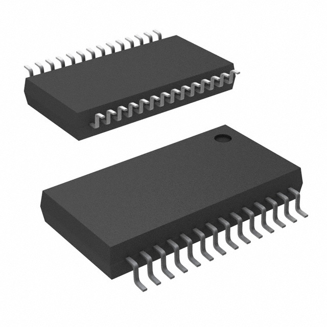
- Part No.:
- DF1704EG4
- Manufacturer:
- Texas Instruments
- Category:
- Audio Special Purpose
- Package:
- 28-SSOP (0.209", 5.30mm Width)
- Datasheet:
-
 DF1704EG4.pdf
- Description:
- IC INTERPOLATION FILTER 28SSOP
- Quantity:
- Payment:

- Shipping:

Inventory:2,379
Please send an inquiry. Send us your inquiry, and we will respond immediately.
Product details
Overview
DF1704EG4 from Texas Instruments is a stereo, 24-bit, 96kHz 8× oversampling digital interpolation filter IC designed for high-end audio systems. It provides programmable filter response (sharp/slow roll-off), digital de-emphasis, independent left/right attenuation, and supports I²S/standard/left-justified input formats with 16–24-bit word lengths. It serves as the companion digital filter to the PCM1704 DAC in premium CD players, DAC modules, and studio-grade audio converters.
For engineers reviewing the DF1704EG4 datasheet, DF1704EG4 pinout, DF1704EG4 application, or DF1704EG4 equivalent, key selection considerations include its 24-bit resolution, –115dB stopband attenuation, software/hardware configuration modes, SSOP-28 package compatibility, and precise 44.1/48/32kHz de-emphasis support - all critical for low-jitter, high-SNR audio signal chain design.
Technical Context
The DF1704EG4 implements an 8× oversampling FIR-based digital interpolation filter with two selectable frequency responses: sharp roll-off (–115dB stopband at 0.546fS, ±0.00005dB passband ripple) and slow roll-off (–100dB stopband at 0.748fS). Its internal architecture includes a 3-wire serial control interface (ML/MC/MD) for register programming in software mode and dedicated Schmitt-trigger input pins (I2S, IW0–IW1, OW0–OW1, SRO, DEM, SF0–SF1) for hardware mode configuration.
It operates on a single +5V supply and integrates an on-chip crystal oscillator (up to 24.576MHz), supporting system clock rates of 256fS, 384fS, 512fS, or 768fS. Audio output is right-justified, MSB-first, with fixed 8fS word clock (WCKO) and BCKO at 256fS (256/512fS system clocks) or 192fS (384/768fS system clocks).
Key Specifications
| Parameter | Value and Actual Design Meaning |
|---|---|
| Resolution | 24-bit - enables >144dB theoretical SNR in ideal conditions |
| Sampling Rate Support | 32kHz to 96kHz - covers CD (44.1kHz), DAT (48kHz), and high-res audio (96kHz) standards |
| Stopband Attenuation | –115dB at 0.546fS - suppresses imaging artifacts beyond audible band with high margin |
| Passband Ripple | ±0.00005dB - preserves amplitude linearity across full audio band (20Hz–20kHz @ 44.1kHz) |
| Oversampling Ratio | 8× - reduces out-of-band quantization noise, easing analog anti-aliasing filter requirements |
| Supply Voltage | +4.5V to +5.5V - compatible with standard 5V logic rails and tolerant of typical board-level variation |
| Operating Temperature | –25°C to +85°C - suitable for consumer and professional equipment enclosures without forced cooling |
Pinout & Package
DF1704EG4 is housed in a 28-pin SSOP (Shrink Small Outline Package) with 0.65mm pitch, optimized for compact high-fidelity audio PCB layouts. Pin 1 is marked by a dot or notch; pin numbering follows standard counter-clockwise orientation.
| Pin/Terminal | Circuit Role | Design Meaning |
|---|---|---|
| DIN (1) | Serial audio data input | MSB-first, two's complement data clocked on rising edge of BCKIN; accepts 16/20/24-bit words |
| BCKIN (2) | Input bit clock | Drives DIN sampling at 32fS/48fS/64fS; must be synchronized to LRCIN within ±6 bit periods |
| I2S (3), IW0 (4), IW1 (5) | Hardware input format/word length select | Set input data format (I2S/standard/left-justified) and bit length (16/20/24) when MODE = L |
| XTI (6), XTO (7) | Crystal oscillator interface | Supports external crystal (e.g., 24.576MHz for 48kHz) or external clock source up to 24.576MHz |
| VSS (8) | Digital ground reference | Must be connected to clean digital ground plane; separate from analog ground except at single-point tie |
| CLKO (9) | Buffered system clock output | Provides 256fS/384fS/512fS/768fS clock; frequency selectable via CKO pin or MODE3 register |
| MODE (10) | Configuration mode select | H = software mode (3-wire control); L = hardware mode (pin-strapped configuration) |
| MD/CKO (11), MC/LRIP (12), ML/RESV (13) | Software control interface / reserved | 3-wire serial port (data/clock/latch) in software mode; RESV pin unused in current revision |
| RST (14) | Asynchronous reset input | Active-low; forces outputs LOW and resets internal state for 1024 system clock cycles |
| MUTE (15), DEM (16), SF0 (17), SF1 (18) | Function enable/control inputs | Enable soft mute, digital de-emphasis, and select de-emphasis sampling rate (44.1/48/32kHz) |
| OW0 (19), OW1 (20) | Output word length select | Configure DOL/DOR output bit width: 16/18/20/24 bits, right-justified, MSB-first |
| SRO (27) | Filter roll-off select | L = sharp roll-off (–115dB stopband); H = slow roll-off (–100dB stopband, wider transition band) |
| LRCIN (28) | Left/right channel clock input | Word latch signal running at fS; polarity configurable via LRIP pin or MODE3 register |
| DOL (24), DOR (23) | Left/right serial audio outputs | Right-justified, MSB-first, two's complement; drive PCM1704 or similar 24-bit DACs directly |
| WCKO (25), BCKO (26) | Output word/bit clocks | WCKO = fixed 8fS; BCKO = 256fS (256/512fS) or 192fS (384/768fS) - synchronized to DOL/DOR edges |
Key Features
| Feature | Design Value |
|---|---|
| Programmable filter response | Sharp or slow roll-off selectable in hardware (SRO pin) or software (MODE3.SRO), enabling trade-off between alias rejection and phase linearity |
| Digital de-emphasis | On-chip 50µs/15µs time-constant de-emphasis for 32/44.1/48kHz sources with ±0.003dB error - eliminates need for external analog circuitry |
| Independent channel attenuation | 8-bit per-channel digital attenuators (–127.5dB to 0dB in 0.5dB steps) controlled via registers MODE0/MODE1 or hardware pins |
| Flexible audio interface | Supports I²S, standard (Sony), and left-justified input formats with 16/20/24-bit word lengths - interoperable with diverse DSPs, receivers, and transport layers |
| Single-supply +5V operation | Eliminates need for dual-rail supplies; 20–30mA IDD enables thermal management in dense audio PCBs without heatsinking |
Applications
| High-Fidelity CD Transport | Studio Reference DAC Module |
|---|---|
Use Scenario: Digital audio output stage of a premium CD player using S/PDIF receiver and discrete DAC architecture. IC Role / Device Role / Timing Role: Interpolation filter providing 8× oversampling and de-emphasis before feeding PCM1704 DACs; synchronizes to 44.1kHz LRCIN and generates WCKO/BCKO clocks. Use Value: Enables >110dB THD+N and <0.0005% distortion by eliminating imaging energy and preserving transient integrity through ultra-low-ripple filtering. | Use Scenario: Modular 24-bit/96kHz DAC board for mastering consoles and audio test equipment. IC Role / Device Role / Timing Role: Precision digital filter co-located with dual PCM1704 channels; configured via software mode for dynamic filter response switching during calibration. Use Value: Delivers –115dB stopband attenuation to prevent ultrasonic feedthrough into analog output stages, ensuring compliance with AES17 measurement standards. |
| USB Audio Interface Front-End | Professional Digital Mixing Console |
Use Scenario: Digital audio processing path in a USB-to-I²S adapter supporting high-res streaming (e.g., TIDAL MQA). IC Role / Device Role / Timing Role: Format converter and interpolator accepting 24-bit/96kHz USB audio stream; re-times and upsamples to match DAC-native clock domain. Use Value: Resolves jitter-sensitive timing mismatch between USB host and DAC by regenerating clean, low-phase-noise BCKO/WCKO derived from on-chip oscillator. | Use Scenario: Channel-specific digital audio conditioning in a 32-channel broadcast mixing console with per-channel digital trim. IC Role / Device Role / Timing Role: Per-channel interpolation and attenuation block; configured in hardware mode for deterministic latency and independent left/right gain control. Use Value: Provides 0.5dB-resolution digital attenuation without clipping or dither-induced noise floor rise, maintaining 114dB dynamic range across full gain range. |
Equivalent & Alternatives
The following parts are listed as comparable options for similar digital interpolation filter applications.
| Alternative Part | Technical Difference | Application Difference | Selection Advice |
|---|---|---|---|
| AK4128VN | 24-bit, 192kHz-capable, integrated sample rate converter; no on-chip oscillator; requires external clock | Supports asynchronous SRC for USB/SPDIF bridging; lacks hardware-mode pin-strapping | Choose AK4128VN when SRC functionality and higher fs support are required; DF1704EG4 preferred for fixed-rate, oscillator-integrated designs |
| CS8416-CQZ | 24-bit, 100kHz max; includes S/PDIF receiver; no programmable filter roll-off or de-emphasis | Integrated receiver simplifies input stage but removes flexibility in filter tuning and de-emphasis control | Choose CS8416-CQZ when S/PDIF demuxing is needed alongside interpolation; DF1704EG4 selected when maximum filter precision and configurability are prioritized |
Compared with AK4128VN and CS8416-CQZ, DF1704EG4 offers superior stopband rejection (–115dB vs. –105dB typical) and integrated oscillator-based clocking - making it optimal for fixed-sample-rate, low-jitter audio systems where external clock dependency must be minimized.
Availability
DF1704EG4 is available at Aetrix Electronics and suitable for high-fidelity CD transports, studio reference DAC modules, and USB audio interface front-ends requiring stable component supply, long-term obsolescence planning, and traceable sourcing for Class-A audio production.
Supply support for DF1704EG4 includes scheduled delivery planning, volume procurement assistance, BOM continuity management, traceable sourcing, and lifecycle availability coordination for OEM customers, industrial embedded developers, connected-device designers, and electronics production programs.
Manufacturer
Texas Instruments is a global semiconductor leader specializing in analog, embedded processing, and high-performance signal chain solutions.
The DF1704EG4 belongs to TI's premium audio digital filter product line, engineered specifically for ultra-low-distortion, high-SNR audio systems where precise digital filtering, flexible interface support, and deterministic timing are essential.
FAQ
What is the primary function of the DF1704EG4 in an audio signal chain?
The DF1704EG4 functions as a high-precision 8× oversampling digital interpolation filter that processes digital audio prior to conversion to analog. It performs sample rate conversion, image rejection, de-emphasis, and format alignment - specifically optimized to pair with the PCM1704 DAC. In every DF1704EG4 implementation, its role is to condition the digital signal for minimal jitter, ultra-low distortion, and accurate spectral reconstruction before the DAC stage.
Does the DF1704EG4 require an external crystal, or does it include an on-chip oscillator?
The DF1704EG4 includes an on-chip crystal oscillator supporting frequencies up to 24.576MHz, eliminating the need for external oscillators in most configurations. Pins XTI and XTO allow connection of a crystal (e.g., 24.576MHz for 48kHz systems) or an external clock source. The DF1704EG4 automatically detects and locks to the system clock multiplier (256fS, 384fS, etc.), making the DF1704EG4 self-synchronizing in oscillator-based designs.
Can the DF1704EG4 operate with sampling rates other than 44.1kHz and 48kHz?
Yes, the DF1704EG4 supports sampling rates from 32kHz to 96kHz, including 32kHz, 44.1kHz, 48kHz, and 96kHz. De-emphasis is explicitly supported only at 32kHz, 44.1kHz, and 48kHz (per SF0/SF1 pin settings or MODE3 register), but full interpolation filtering remains functional across the entire 32–96kHz range. For 96kHz operation, the DF1704EG4 requires an external 24.576MHz clock at XTI since the on-chip oscillator cannot exceed that frequency.
How does the DF1704EG4 handle digital attenuation, and what is its resolution?
The DF1704EG4 provides independent 8-bit digital attenuation for left and right channels, adjustable from –127.5dB to 0dB in 0.5dB increments. Attenuation is implemented via registers MODE0 (left) and MODE1 (right) in software mode, or via hardware pins in hardware mode. When ATC = 1 in MODE3, both channels share the same attenuation value. This precision allows fine-grained level matching in DF1704EG4-based multi-DAC or balanced-output systems without analog trimming.
Is the DF1704EG4 pin-compatible with other members of the DF17xx family, such as the DF1702 or DF1708?
No, the DF1704EG4 is not pin-compatible with DF1702 or DF1708. While all belong to TI's DF17xx digital filter family and share functional similarities, they differ in pin count, pin assignment, and feature set. The DF1704EG4 uses a 28-pin SSOP package with specific control pin allocations (e.g., SRO, DEM, SF0/SF1), whereas DF1702 is 24-pin and DF1708 is 32-pin with expanded functionality. Board layout and firmware for DF1704EG4 cannot be reused without redesign.
DF1704EG4 Specifications
- Product attributes
- Attribute value
- Manufacturer:
- Texas Instruments
- Series:
- SoundPlus™
- Package/Case:
- 28-SSOP (0.209", 5.30mm Width)
- Packaging:
- Tube
- Product Status:
- Discontinued at Digi-Key
- Function:
- Interpolation Filter
- Applications:
- Consumer Audio, Professional Audio
- Number of Channels:
- 2
- Interface:
- I2S
- Voltage - Supply:
- 4.5V ~ 5.5V
- Operating Temperature:
- -25°C ~ 85°C (TA)
- Specifications:
- 32kHz ~ 96kHz
- Mounting Type:
- Surface Mount
- Grade:
- -
DF1704EG4 FAQ
1.How can I place an order for DF1704EG4 through Aetrix?
Please submit a Request for Quotation (RFQ) for DF1704EG4 on Aetrix. Our sales agent will provide a competitive quotation and guide you through the order confirmation once you accept the terms.
2.Are the price and stock information for DF1704EG4 reliable?
The price and inventory of DF1704EG4 are updated periodically and may fluctuate due to market conditions. Stock and pricing data are typically refreshed every 24 hours. Quotation validity for DF1704EG4 is usually 5 days.
3.What payment methods are accepted for DF1704EG4?
We accept Wire Transfer, PayPal, Credit Card, Western Union, MoneyGram, and Escrow for DF1704EG4 transactions.
Note: Certain payment methods may incur a processing fee.
4.How is shipping managed for DF1704EG4?
DF1704EG4 orders can be shipped via leading logistics carriers, including DHL, UPS, FedEx, TNT, or Registered Mail.
Once your DF1704EG4 order is processed, you will receive an email with the shipment details and tracking number.
Note: Tracking information may take up to 24 hours to appear. Express delivery typically takes 3–5 business days.
5.How can I obtain technical support or documentation for DF1704EG4?
For technical support, including DF1704EG4 datasheets, pinout diagrams, or application guidance, please contact our engineering support team. They can provide detailed documentation and assistance for your DF1704EG4 requirements.
6.How does Aetrix verify that DF1704EG4 is sourced from the original manufacturer or authorized distributors?
All DF1704EG4 products on Aetrix are procured from qualified distributors and authorized channels. Our dedicated quality assurance team conducts strict verification, including traceability checks and, if necessary, third-party testing. This ensures that DF1704EG4 meets industry standards.
7.What is the process for return or replacement of DF1704EG4?
All DF1704EG4 units undergo pre-shipment inspection (PSI). If there is an issue with DF1704EG4, returns or replacements are accepted under the following conditions:
1.Quantity discrepancies, incorrect items, or visible external defects (such as breakage or corrosion), acknowledged by Aetrix.
2.The issue is reported within 90 days of delivery.
3.The DF1704EG4 part is unused and in its original packaging.
Return procedure for DF1704EG4:
1.Submit a request within 90 days.
2.Obtain a Return Material Authorization (RMA) from Aetrix.
DF1704EG4 Tags

-
SA571DR2G
onsemi

-
ADAU7002ACBZ-R7
Analog Devices Inc.

-
DRV135UA/2K5
Texas Instruments

-
DRV134UA/1K
Texas Instruments

-
DRV134PA
Texas Instruments
-
DRV134UA
Texas Instruments
-
DRV135UA
Texas Instruments
-
SA572DR2G
onsemi
-
PGA2311U/1K
Texas Instruments

-
SI8244BB-D-IS1R
Skyworks Solutions Inc.

-
CS8416K-CZZR
Cirrus Logic Inc.

-
SRC4392IPFBR
Texas Instruments
Tech Hub

A practical engineering guide to 3.3V and 5V logic compatibility, input thresholds, resistor dividers, translator ICs, MOSFET level shifting, I2C pull-ups, timing limits and power-sequencing risks.

The 74HC595 uses push-pull logic outputs, while the TPIC6B595 uses 50 V open-drain DMOS sinks for higher-power loads. This guide compares timing, current limits, 3.3 V interfacing, load wiring, thermal…

The 74HC595 converts serial data into eight stable parallel outputs. This guide covers pin functions, shift and storage timing, OE and MR behavior, drive-current limits, cascading, voltage compatibilit…

A technical comparison of level-sensitive latches and edge-triggered flip-flops, covering timing windows, setup and hold limits, master–slave operation, time borrowing, race-through, HDL inference and…

A D latch stores one bit while Enable controls when data can pass. This reference covers gate-level operation, truth tables, transparency, setup and hold timing, LE versus OE, common ICs and practical …

An SR latch stores one bit through cross-coupled feedback. This engineering reference covers NOR and NAND implementations, truth tables, forbidden-state recovery, gated operation, switch debouncing, fa…

Latch circuits retain one bit through feedback. This technical reference covers SR and D latches, truth tables, transparency, timing limits, latch-versus-flip-flop behavior, applications and common log…

An engineering guide to LED driver operation, constant-current and constant-voltage outputs, linear and switching topologies, dimming, IC selection, calculations, replacement compatibility, and fault c…

Operational amplifier guide covering op amp basics, feedback, ideal vs real op amps, common configurations, buffer circuits, offset, bias current, gain-bandwidth, slew rate, rail-to-rail limits and sel…

Jumper cables guide covering safe connection order, red and black clamp placement, final ground connection, cable gauge, length, clamp quality, copper vs CCA cables, jump starter comparison and battery…


