Send an Inquiry

To receive a quote for your project, please fill in the following information, and we’ll get back to you promptly.

Name*
Company*
Email Address*
Phone/WhatsApp
Part Number*
Quantity*
Message
Submit Inventory List

Please fill in the following information, and we’ll get back to you promptly.

Name*
Company*
Email Address*
Phone/WhatsApp
Upload My List
Message

Vishay Siliconix DG201BDY-E3

Part No.:
DG201BDY-E3
Manufacturer:
Vishay Siliconix
Category:
Analog Switches, Multiplexers, Demultiplexers
Package:
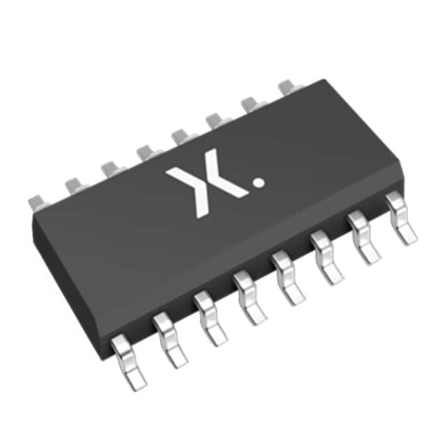
16-SOIC (0.154", 3.90mm Width)
Datasheet:
AetrixDG201BDY-E3.pdf
Description:
IC SWITCH SPST-NCX4 85OHM 16SOIC
Quantity:
Payment:
Payment
Shipping:
Shipping

Inventory:7,902

Please send an inquiry. Send us your inquiry, and we will respond immediately.

Part Number
Quantity*
Price
Name*
Company
Email*
Comments

Product details

Overview

DG201BDY-E3 from Vishay Siliconix is a quad single-pole single-throw (SPST) normally closed analog switch fabricated in silicon gate CMOS technology, rated for ±22 V analog signal range, 45 Ω on-resistance, and 120 ns turn-on time, used in precision sample-and-hold circuits and digitally programmable filter designs.

For engineers reviewing the DG201BDY-E3 datasheet, DG201BDY-E3 pinout, DG201BDY-E3 application, or DG201BDY-E3 equivalent, key selection criteria include bi-directional signal handling, low 1 pC charge injection, ±22 V dual-supply operation, 20 pA leakage, and TSSOP-16 package compatibility with industrial instrumentation and test equipment layouts.

Technical Context

The DG201BDY-E3 implements four independent SPST switches with normally closed logic behavior (ON at logic low), each featuring true bi-directional conduction and rail-to-rail analog signal switching up to ±22 V. Its epitaxial layer prevents latch-up, and improved charge injection compensation minimizes transients during switching.

It supports both dual-supply (±4.5 V to ±22 V) and single-supply (4.5 V to 25 V) operation, with TTL/CMOS-compatible digital inputs (0.8 V low, 2.4 V high) and guaranteed 30 mA continuous current per channel. Off-isolation exceeds 90 dB at 100 kHz, and crosstalk remains below –95 dB.

Key Specifications

ParameterValue and Actual Design Meaning
Analog Signal Range±15 V (dual supply); enables full-range signal routing without clipping in ±15 V systems
On-Resistance45 Ω typical (RDS(on)); ensures minimal voltage drop and signal attenuation in precision analog paths
Charge Injection1 pC typical; reduces acquisition error in sample-and-hold applications to sub-mV levels
Turn-On Time120 ns typical; supports sampling rates up to ~5 MHz in fast-switching data acquisition
Off-Leakage Current±20 pA max (IS(off), ID(off)); preserves signal integrity in high-impedance sensor interfaces
Supply Voltage Range±4.5 V to ±22 V (dual); accommodates legacy ±15 V and extended-range industrial supplies
Logic CompatibilityTTL/CMOS (0.8 V low / 2.4 V high); interfaces directly with microcontrollers and FPGAs without level shifters

Pinout & Package

Package: 16-pin TSSOP (JEDEC MO-153, MS-012 variant), 4.4 mm × 5.0 mm footprint, 0.65 mm pitch, 1.2 mm max height - optimized for space-constrained PCBs in portable instruments and automated test equipment.

Pin/TerminalCircuit RoleDesign Meaning
1, 2, 3, 4 (IN1–IN4)Digital control inputActive-low logic: low = ON (closed) for DG201BDY-E3; drives internal switch gate
5, 6, 12, 13 (S1–S4)Source terminalBi-directional analog path input/output; connects to signal source or load
7, 8, 11, 14 (D1–D4)Drain terminalBi-directional analog path input/output; completes switched path with corresponding Sx
9 (V−)Negative supply railBias reference for negative analog swing; must be connected for dual-supply operation
10 (GND)Digital groundReference for logic inputs; tied to system digital ground plane
15, 16 (V+)Positive supply railBias reference for positive analog swing; dual connection improves PSRR and noise immunity
NC (Pin 15 not used)No connectPin 15 is internally unconnected; must remain floating or grounded per layout guidelines

Key Features

FeatureDesign Value
Normally closed topologyEnsures fail-safe signal continuity during power loss or logic fault in critical monitoring paths
Rail-to-rail analog switchingSupports signals from V− to V+ without clamping or distortion, essential for ±15 V op-amp interfaces
Low glitch energy (1 pC)Minimizes voltage step errors in sample-and-hold amplifiers, enabling <5 mV sample-to-hold offset
Latch-up immunityEpitaxial substrate prevents destructive latch-up under transient overvoltage or ESD stress
Pb-free RoHS-compliant terminationE3 suffix denotes lead-free matte tin plating, compliant with Directive 2002/95/EC for global manufacturing

Applications

Industrial InstrumentationTest Equipment

Use Scenario: Multiplexing sensor inputs (thermocouples, strain gauges) into a shared ADC front-end in a modular data logger.

IC Role / Device Role / Timing Role: Quad SPST analog switch routing four differential sensor channels with minimal crosstalk and offset drift.

Use Value: 95 dB channel-to-channel isolation and <20 pA leakage preserve microvolt-level signal fidelity across temperature ranges.

Use Scenario: Configurable gain and filter breakpoint selection in automated benchtop signal analyzers.

IC Role / Device Role / Timing Role: Digitally controlled switch selecting capacitor banks in active low-pass filter topologies.

Use Value: 45 Ω RDS(on) and 120 ns tON enable stable cutoff frequency switching without settling artifacts.

Sample-and-Hold CircuitsCommunications Systems

Use Scenario: Precision acquisition stage in high-speed data converters for oscilloscope front-ends.

IC Role / Device Role / Timing Role: Normally closed switch isolating hold capacitor during acquisition phase; opens on command to freeze voltage.

Use Value: 1 pC charge injection limits aperture error to <1 LSB in 14-bit systems using 1 nF hold capacitors.

Use Scenario: Signal path routing and protection in RF transceiver baseband sections.

IC Role / Device Role / Timing Role: Analog multiplexer managing multiple IF signal sources before ADC or DAC stages.

Use Value: ±22 V rating handles transient surges common in telecom line cards; 90 dB off-isolation suppresses inter-channel interference.

Equivalent & Alternatives

The following parts are listed as comparable options for similar analog switch applications.

Alternative PartTechnical DifferenceApplication DifferenceSelection Advice
MAX4617ESE+Quad SPST NC, 35 Ω RDS(on), 100 ns tON, ±20 V rating, SOIC-16 packageLower on-resistance but narrower supply range; no TSSOP optionPreferred when lower on-resistance is critical and SOIC-16 footprint is acceptable
ADG1419BRUZQuad SPST NC, 2.6 Ω RDS(on), 125 ns tON, ±15 V rating, TSSOP-16, higher costSuperior on-resistance and THD, but limited to ±15 V; not suitable for ±22 V systemsSelect only if ±22 V operation is unnecessary and ultra-low on-resistance justifies premium cost

Compared with MAX4617ESE+ and ADG1419BRUZ, the DG201BDY-E3 uniquely balances ±22 V capability, 45 Ω on-resistance, and TSSOP-16 packaging-making it optimal for industrial systems requiring extended voltage range and board-space efficiency without premium pricing.

Availability

DG201BDY-E3 is available at Aetrix Electronics and suitable for industrial instrumentation, automated test equipment, and precision data acquisition systems requiring stable component supply, long-term lifecycle support, and RoHS-compliant sourcing.

Supply support for DG201BDY-E3 includes scheduled delivery planning, volume procurement assistance, BOM continuity management, traceable sourcing, and lifecycle availability coordination for OEM customers, industrial embedded developers, connected-device designers, and electronics production programs.

Manufacturer

Vishay Siliconix is a global semiconductor manufacturer specializing in discrete components and analog ICs, with leadership in MOSFETs, diodes, optoelectronics, and precision analog switches.

The DG201B series belongs to Vishay's high-performance analog switch product line, engineered for industrial-grade reliability, wide supply tolerance, and low-distortion signal routing in measurement and control systems.

FAQ

What is the maximum analog signal voltage supported by the DG201BDY-E3?

The DG201BDY-E3 supports analog signals from V− to V+, with absolute maximum ratings of ±22 V across the V+ to V− terminals. In dual-supply operation at ±15 V, it guarantees full ±15 V analog signal range without clipping or distortion, making DG201BDY-E3 suitable for legacy industrial systems using standard ±15 V rails.

Is the DG201BDY-E3 pin-compatible with the older DG201A series?

Yes, the DG201BDY-E3 is a direct functional and pin-compatible upgrade to the DG201A, retaining identical pinout, package dimensions, and logic behavior. DG201BDY-E3 improves on-resistance (45 Ω vs. 60 Ω), leakage (20 pA vs. 100 pA), and switching speed (120 ns vs. 175 ns), while maintaining backward compatibility in existing SOIC-16 and TSSOP-16 layouts.

Does the DG201BDY-E3 require separate ground connections for analog and digital domains?

No, the DG201BDY-E3 uses a single GND pin (Pin 10) for digital logic reference and does not isolate analog and digital grounds. System-level separation must be implemented externally via PCB layout-using split ground planes and star grounding near the device-to maintain low-noise performance, especially in mixed-signal applications where DG201BDY-E3 routes sensitive analog signals.

Can the DG201BDY-E3 operate from a single +12 V supply?

Yes, the DG201BDY-E3 supports single-supply operation from +4.5 V to +25 V. At +12 V, it delivers an analog signal range of 0 V to +12 V, with RDS(on) rising to 90 Ω typical and charge injection increasing to 4 pC. This mode is validated in the datasheet and appropriate for DG201BDY-E3 use in battery-powered portable instruments where dual supplies are impractical.

What is the thermal derating behavior of the DG201BDY-E3 above 75 °C?

Above 75 °C, the DG201BDY-E3 derates power dissipation at 12 mW/°C for TSSOP-16 packages. With a maximum rated power dissipation of 640 mW at 75 °C, its usable limit drops to ~520 mW at 85 °C and ~400 mW at 95 °C. This derating ensures safe junction temperature operation and must be factored into thermal design when DG201BDY-E3 switches high-current analog signals continuously.

DG201BDY-E3 Specifications

Product attributes
Attribute value
Manufacturer:
Vishay Siliconix
Series:
-
Packaging:
Tube
Product Status:
Active
Switch Circuit:
SPST - NC
Multiplexer/Demultiplexer Circuit:
1:1
Number of Circuits:
4
On-State Resistance (Max):
85Ohm
Channel-to-Channel Matching (ΔRon):
2Ohm
Voltage - Supply, Single (V+):
4.5V ~ 25V
Voltage - Supply, Dual (V±):
±4.5V ~ 22V
Switch Time (Ton, Toff) (Max):
300ns, 200ns
-3db Bandwidth:
-
Charge Injection:
1pC
Channel Capacitance (CS(off), CD(off)):
5pF, 5pF
Current - Leakage (IS(off)) (Max):
500pA
Crosstalk:
-95dB @ 100kHz
Operating Temperature:
-40°C ~ 85°C (TA)
Grade:
-
Qualification:
-
Mounting Type:
Surface Mount
Supplier Device Package:
16-SOIC

DG201BDY-E3 FAQ

1.How can I place an order for DG201BDY-E3 through Aetrix?

Please submit a Request for Quotation (RFQ) for DG201BDY-E3 on Aetrix. Our sales agent will provide a competitive quotation and guide you through the order confirmation once you accept the terms.

2.Are the price and stock information for DG201BDY-E3 reliable?

The price and inventory of DG201BDY-E3 are updated periodically and may fluctuate due to market conditions. Stock and pricing data are typically refreshed every 24 hours. Quotation validity for DG201BDY-E3 is usually 5 days.

3.What payment methods are accepted for DG201BDY-E3?

We accept Wire Transfer, PayPal, Credit Card, Western Union, MoneyGram, and Escrow for DG201BDY-E3 transactions.

Note: Certain payment methods may incur a processing fee.

4.How is shipping managed for DG201BDY-E3?

DG201BDY-E3 orders can be shipped via leading logistics carriers, including DHL, UPS, FedEx, TNT, or Registered Mail.

Once your DG201BDY-E3 order is processed, you will receive an email with the shipment details and tracking number.

Note: Tracking information may take up to 24 hours to appear. Express delivery typically takes 3–5 business days.

5.How can I obtain technical support or documentation for DG201BDY-E3?

For technical support, including DG201BDY-E3 datasheets, pinout diagrams, or application guidance, please contact our engineering support team. They can provide detailed documentation and assistance for your DG201BDY-E3 requirements.

6.How does Aetrix verify that DG201BDY-E3 is sourced from the original manufacturer or authorized distributors?

All DG201BDY-E3 products on Aetrix are procured from qualified distributors and authorized channels. Our dedicated quality assurance team conducts strict verification, including traceability checks and, if necessary, third-party testing. This ensures that DG201BDY-E3 meets industry standards.

7.What is the process for return or replacement of DG201BDY-E3?

All DG201BDY-E3 units undergo pre-shipment inspection (PSI). If there is an issue with DG201BDY-E3, returns or replacements are accepted under the following conditions:

1.Quantity discrepancies, incorrect items, or visible external defects (such as breakage or corrosion), acknowledged by Aetrix.

2.The issue is reported within 90 days of delivery.

3.The DG201BDY-E3 part is unused and in its original packaging.

Return procedure for DG201BDY-E3:

1.Submit a request within 90 days.

2.Obtain a Return Material Authorization (RMA) from Aetrix.

DG201BDY-E3 Tags

  • DG201BDY-E3
  • DG201BDY-E3 PDF
  • DG201BDY-E3 Datasheet
  • DG201BDY-E3 Specifications
  • DG201BDY-E3 Images
  • Vishay Siliconix
  • Vishay Siliconix DG201BDY-E3
  • Buy DG201BDY-E3
  • DG201BDY-E3 Price
  • DG201BDY-E3 Distributor
  • DG201BDY-E3 Supplier
  • DG201BDY-E3 Wholesale
Related Products
SN74LVC1G3157DBVR
SN74LVC1G3157DBVR

Texas Instruments

SN74LVC1G66DBVR
SN74LVC1G66DBVR

Texas Instruments

SN74LVC1G66DCKR
SN74LVC1G66DCKR

Texas Instruments

SN74LVC1G3157DSFR
SN74LVC1G3157DSFR

Texas Instruments

1P1G3157QDCKRQ1
1P1G3157QDCKRQ1

Texas Instruments

SN74LVC2G66DCUR
SN74LVC2G66DCUR

Texas Instruments

SN74LV4052APWR
SN74LV4052APWR

Texas Instruments

74HC4051D,653
74HC4051D,653

Nexperia USA Inc.

SN74LV4051APWR
SN74LV4051APWR

Texas Instruments

CD74HC4052PWR
CD74HC4052PWR

Texas Instruments

CD74HC4051PWR
CD74HC4051PWR

Texas Instruments

TS5A3166DBVR
TS5A3166DBVR

Texas Instruments

Tech Hub

Search

Search

PRODUCT

PRODUCT

PHONE

PHONE

USER

USER