
 My Inquiry
 My Account


STMicroelectronics DIP1524-01D3

- Part No.:
- DIP1524-01D3
- Manufacturer:
- STMicroelectronics
- Category:
- RF Multiplexers
- Package:
- 4-UFBGA, FCBGA
- Datasheet:
-
 DIP1524-01D3.pdf
- Description:
- RF DIPLX 1589.655MHZ/2.55GHZ BGA
- Quantity:
- Payment:

- Shipping:

Inventory:3,469
Please send an inquiry. Send us your inquiry, and we will respond immediately.
Product details
Overview
DIP1524-01D3 from STMicroelectronics is a GPS/GLONASS and 2.4 GHz RF diplexer designed to separate GPS-GLONASS received signals from RF received signals in the 2.4 GHz to 2.7 GHz band. The device uses STMicroelectronics IPD integrated passive device technology on a non-conductive glass substrate and is supplied in a 4-bump Flip-Chip package for compact RF front-end integration.
For engineers reviewing the DIP1524-01D3 datasheet, DIP1524-01D3 pinout, DIP1524-01D3 application, or DIP1524-01D3 equivalent, this RF diplexer is most relevant for multi-band front-end modules, mobile handsets, GPS/GLONASS receiver paths, WLAN / Bluetooth / LTE Band VII coexistence designs, and compact antenna-sharing circuits requiring low insertion loss, high attenuation between bands, and a very low-profile chip-scale package.
Technical Context
DIP1524-01D3 routes the WLAN / Bluetooth / LTE Band VII path through P1 to P3 over the 2400 MHz to 2700 MHz band, while the GPS/GLONASS receiver path is routed through P2 to P3 over 1573.42 MHz to 1605.89 MHz. The RF table lists P1-P3 insertion loss of 0.85 dB typical and 0.90 dB maximum in the 2.4 GHz band, with P2-P3 insertion loss of 0.60 dB typical and 0.65 dB maximum for GPS and 0.65 dB typical and 0.75 dB maximum for GLONASS.
The diplexer provides attenuation between the two RF paths, with 20 dB minimum attenuation from P1-P3 in the GPS/GLONASS band and 18 dB minimum attenuation from P2-P3 in the 2.4 GHz band. Maximum RF input power is 28 dBm on P1 and 25 dBm on P2, supporting integration into multi-band RF modules where WLAN/Bluetooth/LTE and satellite-navigation receive paths share a compact antenna-side passive network.
Key Specifications
| Parameter | Value and Actual Design Meaning |
|---|---|
| Device Type | GPS/GLONASS and 2.4 GHz RF diplexer using STMicroelectronics IPD technology on non-conductive glass substrate. |
| RF Function | Separates GPS/GLONASS received signals from WLAN, Bluetooth, and LTE Band VII RF received signals. |
| 2.4 GHz Path | P1-P3 path covers 2400 MHz to 2700 MHz for WLAN, Bluetooth, and LTE Band VII band routing. |
| GPS/GLONASS Path | P2-P3 path covers GPS at 1573.42 MHz to 1577.42 MHz and GLONASS at 1597.55 MHz to 1605.89 MHz. |
| Insertion Loss | P1-P3: 0.85 dB typical / 0.90 dB maximum in f1; P2-P3: 0.60 dB typical / 0.65 dB maximum for GPS and 0.65 dB typical / 0.75 dB maximum for GLONASS. |
| Band Attenuation | 20 dB minimum attenuation from P1-P3 in f2 and 18 dB minimum attenuation from P2-P3 in f1, helping isolate the two RF receive paths. |
| Return Loss | P1 return loss is 10 dB minimum in f1, P2 return loss is 20 dB minimum in f2, and P3 return loss is 9.5 dB minimum in f1 and f2. |
| Maximum Input Power | 28 dBm maximum on P1 and 25 dBm maximum on P2, supporting RF front-end module use under the specified port conditions. |
| ESD Ratings | 300 V HBM, 100 V machine model, and 500 V charged device model on all I/O pins. |
| Operating Temperature | -30°C to +85°C operating temperature range for mobile and compact RF module environments. |
| Package | Lead-free 4-bump Flip-Chip package with approximately 840 µm × 1360 µm body size and less than 630 µm thickness. |
| Ordering and Marking | Order code DIP1524-01D3, marking RT, 1.35 mg package weight, 5000-unit 7-inch tape-and-reel delivery. |
Pinout & Package
DIP1524-01D3 is supplied in a lead-free 4-bump Flip-Chip package on glass substrate, with a very low profile below 630 µm and a compact footprint suitable for dense RF front-end layouts. The package uses a 400 µm bump pitch and supports short RF routing from antenna, GPS/GLONASS, and 2.4 GHz paths, helping reduce parasitic effects and board area in mobile RF modules.
| Pin / Terminal | Circuit Role | Design Meaning |
|---|---|---|
| P1 | WLAN, Bluetooth, and LTE Band VII RF port. | Connects the 2400 MHz to 2700 MHz path to the shared antenna port, allowing the 2.4 GHz receive band to pass with low insertion loss while attenuating the GPS/GLONASS band. |
| P2 | GPS/GLONASS receiver RF port. | Connects the 1573.42 MHz to 1605.89 MHz satellite-navigation receive path to the shared antenna port, allowing GPS and GLONASS signals to pass while attenuating the 2.4 GHz band. |
| P3 | Common RF antenna port. | Connects to the shared receive antenna node, combining the separated 2.4 GHz and GPS/GLONASS RF paths through the diplexer structure. |
| GND | Ground bump for RF reference and isolation. | Provides the RF ground reference for the integrated passive network and supports the attenuation and return-loss behavior of the diplexer when connected to the local RF ground plane. |
Key Features
- GPS/GLONASS and 2.4 GHz RF diplexer for separating satellite-navigation and WLAN / Bluetooth / LTE Band VII receive paths.
- 2400 MHz to 2700 MHz f1 pass band and 1573.42 MHz to 1605.89 MHz GPS/GLONASS f2 pass band.
- Low insertion loss: up to 0.90 dB maximum on the 2.4 GHz path and up to 0.75 dB maximum on the GLONASS path.
- 20 dB minimum attenuation in the GPS/GLONASS band from P1-P3 and 18 dB minimum attenuation in the 2.4 GHz band from P2-P3.
- 28 dBm maximum input power on P1 and 25 dBm maximum input power on P2 for RF front-end module use.
- 4-bump lead-free Flip-Chip package using ST IPD technology on non-conductive glass substrate.
Applications
| Multi-Band RF Front-End Modules | GPS/GLONASS Receiver Paths |
|---|---|
|
Use Scenario: Mobile RF front ends combining 2.4 GHz WLAN / Bluetooth / LTE Band VII and satellite-navigation receive paths. Device Role: Integrated passive RF diplexer connected between band-specific RF paths and a shared antenna node. Use Value: The P1-P3 and P2-P3 pass bands separate RF traffic while reducing the need for a larger discrete passive filter network. |
Use Scenario: GPS and GLONASS receive circuits operating from 1573.42 MHz to 1605.89 MHz. Device Role: Low-loss GPS/GLONASS path from P2 to the common antenna port P3. Use Value: 0.65 dB maximum GPS insertion loss and 0.75 dB maximum GLONASS insertion loss help preserve weak satellite-navigation receive signals. |
| WLAN / Bluetooth Coexistence | Compact Smartphone and Tablet Layouts |
|
Use Scenario: 2.4 GHz RF receive paths for WLAN, Bluetooth, and LTE Band VII coexistence in multi-radio platforms. Device Role: RF diplexer path passing 2400 MHz to 2700 MHz from P1 to P3. Use Value: 0.90 dB maximum insertion loss and 18 dB minimum GPS-band isolation support shared-antenna receive designs. |
Use Scenario: Netbook, tablet, smartphone, and mobile phone RF boards with restricted component height and footprint. Device Role: Very low-profile 4-bump integrated passive RF component. Use Value: The sub-630 µm Flip-Chip package and IPD construction support dense RF routing near the antenna switch or front-end module. |
Equivalent & Alternatives
When evaluating DIP1524-01D3 equivalent devices, engineers should compare RF band split, insertion loss, attenuation between paths, input power rating, return loss, package pitch, antenna-port routing, and whether the design separates GPS/GLONASS from 2.4 GHz traffic or separates different WLAN frequency bands.
| Alternative Part | Technical Difference | Application Difference | Selection Advice |
|---|---|---|---|
| DIP2450-01D3 | STMicroelectronics IPD diplexer in a similar 4-bump WLCSP / Flip-Chip package, but designed for 2.4 GHz and 5 GHz WLAN bands rather than GPS/GLONASS plus 2.4 GHz separation. | Used for dual-band WLAN / Bluetooth front ends requiring 2.4 GHz and 5 GHz separation instead of satellite-navigation coexistence. | Select DIP1524-01D3 when the RF design must split GPS/GLONASS from 2.4 GHz paths; select DIP2450-01D3 only when the circuit requirement is 2.4 GHz / 5 GHz WLAN diplexing. |
Compared with DIP2450-01D3, DIP1524-01D3 is optimized for GPS/GLONASS and 2.4 GHz RF coexistence rather than dual-band WLAN routing. DIP1524-01D3 vs DIP2450-01D3 selection depends mainly on the required pass bands, shared antenna architecture, RF isolation target, and whether the system includes a satellite-navigation receive path.
Quality
DIP1524-01D3 should be sourced as original STMicroelectronics components through traceable and controlled supply channels. Quality verification procedures may include Flip-Chip package inspection, RT marking validation, reel and label verification, solderability and bump-condition review, RF insertion-loss screening, attenuation and return-loss verification, port-to-port continuity checks, and incoming inspection according to RF front-end module production requirements.
Availability
DIP1524-01D3 is available at Aetrix Electronics and suitable for GPS/GLONASS receiver front ends, 2.4 GHz RF coexistence modules, multi-band mobile RF designs, and compact antenna-sharing circuits requiring stable component supply and repeatable production support.
Supply support may include scheduled delivery planning, volume procurement support, BOM continuity assistance, traceable sourcing management, and long-term availability support for OEM manufacturers, RF module builders, smartphone hardware designers, tablet platform developers, and electronics production programs.
For production deployment, confirming the 4-bump Flip-Chip package, P1 / P2 / P3 RF port mapping, GPS/GLONASS and 2.4 GHz pass-band requirements, insertion-loss budget, attenuation target, environmental specifications, and sourcing continuity helps reduce procurement risk and improve manufacturing stability.
Manufacturer
STMicroelectronics supplies integrated passive devices, RF filters, baluns, diplexers, protection components, and semiconductor solutions for mobile, wireless, industrial, and embedded applications. DIP1524-01D3 belongs to ST's IPD RF component portfolio, using glass-substrate integrated passive technology to combine compact package size with RF filtering and band-separation performance.
FAQ
What is DIP1524-01D3 used for?
DIP1524-01D3 is used to separate GPS/GLONASS receive signals from WLAN, Bluetooth, and LTE Band VII signals in the 2.4 GHz to 2.7 GHz band. It is used in multi-band RF front-end modules, mobile phones, smartphones, tablets, netbooks, and antenna-sharing RF receive designs.
What frequency bands does DIP1524-01D3 support?
DIP1524-01D3 supports a 2400 MHz to 2700 MHz f1 path for WLAN, Bluetooth, and LTE Band VII through P1-P3, and a GPS/GLONASS f2 path from 1573.42 MHz to 1605.89 MHz through P2-P3.
Is DIP1524-01D3 an active RF IC?
No. DIP1524-01D3 is an integrated passive RF diplexer made with STMicroelectronics IPD technology on a non-conductive glass substrate. It does not require a supply voltage or logic control pins; its function is defined by the passive RF network between P1, P2, P3, and GND.
What package is used by DIP1524-01D3?
DIP1524-01D3 uses a lead-free 4-bump Flip-Chip package with a compact body around 840 µm × 1360 µm and thickness below 630 µm. The package is intended for dense RF module layouts requiring short antenna and band-path routing.
What should be considered in DIP1524-01D3 pinout design?
DIP1524-01D3 pinout design should keep P1, P2, and P3 RF traces short and impedance-controlled. P1 should route to the WLAN / Bluetooth / LTE Band VII path, P2 to the GPS/GLONASS receive path, P3 to the shared antenna node, and GND to a low-inductance RF ground connection.
What is a common DIP1524-01D3 alternative?
DIP2450-01D3 is a related STMicroelectronics IPD diplexer, but it is designed for 2.4 GHz and 5 GHz WLAN separation rather than GPS/GLONASS and 2.4 GHz separation. It should only be considered when the RF band plan matches a dual-band WLAN requirement.
DIP1524-01D3 Specifications
- Product attributes
- Attribute value
- Manufacturer:
- STMicroelectronics
- Series:
- -
- Package/Case:
- 4-UFBGA, FCBGA
- Packaging:
- Tape & Reel (TR)
- Product Status:
- Active
- Type:
- Diplexer
- Frequency Bands (Low / High):
- 1573.42MHz ~ 1605.89MHz / 2.4GHz ~ 2.7GHz
- Low Band Attenuation (min / max dB):
- 20.00dB / -
- High Band Attenuation (min / max dB):
- 18.00dB / -
- Return Loss (Low Band / High Band):
- 10.0dB / 20.0dB
- Grade:
- -
- Qualification:
- -
- Mounting Type:
- Surface Mount
DIP1524-01D3 FAQ
1.How can I place an order for DIP1524-01D3 through Aetrix?
Please submit a Request for Quotation (RFQ) for DIP1524-01D3 on Aetrix. Our sales agent will provide a competitive quotation and guide you through the order confirmation once you accept the terms.
2.Are the price and stock information for DIP1524-01D3 reliable?
The price and inventory of DIP1524-01D3 are updated periodically and may fluctuate due to market conditions. Stock and pricing data are typically refreshed every 24 hours. Quotation validity for DIP1524-01D3 is usually 5 days.
3.What payment methods are accepted for DIP1524-01D3?
We accept Wire Transfer, PayPal, Credit Card, Western Union, MoneyGram, and Escrow for DIP1524-01D3 transactions.
Note: Certain payment methods may incur a processing fee.
4.How is shipping managed for DIP1524-01D3?
DIP1524-01D3 orders can be shipped via leading logistics carriers, including DHL, UPS, FedEx, TNT, or Registered Mail.
Once your DIP1524-01D3 order is processed, you will receive an email with the shipment details and tracking number.
Note: Tracking information may take up to 24 hours to appear. Express delivery typically takes 3–5 business days.
5.How can I obtain technical support or documentation for DIP1524-01D3?
For technical support, including DIP1524-01D3 datasheets, pinout diagrams, or application guidance, please contact our engineering support team. They can provide detailed documentation and assistance for your DIP1524-01D3 requirements.
6.How does Aetrix verify that DIP1524-01D3 is sourced from the original manufacturer or authorized distributors?
All DIP1524-01D3 products on Aetrix are procured from qualified distributors and authorized channels. Our dedicated quality assurance team conducts strict verification, including traceability checks and, if necessary, third-party testing. This ensures that DIP1524-01D3 meets industry standards.
7.What is the process for return or replacement of DIP1524-01D3?
All DIP1524-01D3 units undergo pre-shipment inspection (PSI). If there is an issue with DIP1524-01D3, returns or replacements are accepted under the following conditions:
1.Quantity discrepancies, incorrect items, or visible external defects (such as breakage or corrosion), acknowledged by Aetrix.
2.The issue is reported within 90 days of delivery.
3.The DIP1524-01D3 part is unused and in its original packaging.
Return procedure for DIP1524-01D3:
1.Submit a request within 90 days.
2.Obtain a Return Material Authorization (RMA) from Aetrix.
DIP1524-01D3 Tags
-
DPX202700DT-4062A1
TDK Corporation

-
LDPQ-132-33+
Mini-Circuits
-
LDPW-162-242+
Mini-Circuits
-
DPX1608LL80R2455A
Pulse Electronics
-
DPX162690DT-8058A1
TDK Corporation
-
DPX105950DT-6112A2
TDK Corporation
-
LFD182G45DCJD247
Murata Electronics
-
DPX165950DT-8148A1
TDK Corporation
-
DPX165950DT-8048A1
TDK Corporation
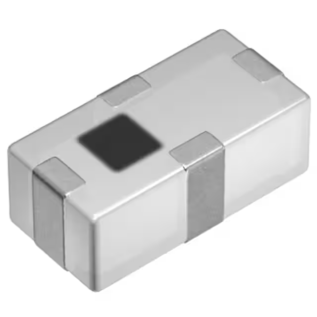
-
DPX165850DT-8032A1
TDK Corporation
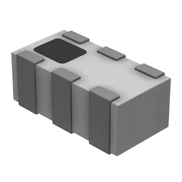
-
DPX165950DT-8026A1
TDK Corporation
-
B39162B9973P810
Qualcomm (RF front-end (RFFE) filters)
Tech Hub

A practical engineering guide to 3.3V and 5V logic compatibility, input thresholds, resistor dividers, translator ICs, MOSFET level shifting, I2C pull-ups, timing limits and power-sequencing risks.

The 74HC595 uses push-pull logic outputs, while the TPIC6B595 uses 50 V open-drain DMOS sinks for higher-power loads. This guide compares timing, current limits, 3.3 V interfacing, load wiring, thermal…

The 74HC595 converts serial data into eight stable parallel outputs. This guide covers pin functions, shift and storage timing, OE and MR behavior, drive-current limits, cascading, voltage compatibilit…

A technical comparison of level-sensitive latches and edge-triggered flip-flops, covering timing windows, setup and hold limits, master–slave operation, time borrowing, race-through, HDL inference and…

A D latch stores one bit while Enable controls when data can pass. This reference covers gate-level operation, truth tables, transparency, setup and hold timing, LE versus OE, common ICs and practical …

An SR latch stores one bit through cross-coupled feedback. This engineering reference covers NOR and NAND implementations, truth tables, forbidden-state recovery, gated operation, switch debouncing, fa…

Latch circuits retain one bit through feedback. This technical reference covers SR and D latches, truth tables, transparency, timing limits, latch-versus-flip-flop behavior, applications and common log…

An engineering guide to LED driver operation, constant-current and constant-voltage outputs, linear and switching topologies, dimming, IC selection, calculations, replacement compatibility, and fault c…

Operational amplifier guide covering op amp basics, feedback, ideal vs real op amps, common configurations, buffer circuits, offset, bias current, gain-bandwidth, slew rate, rail-to-rail limits and sel…

Jumper cables guide covering safe connection order, red and black clamp placement, final ground connection, cable gauge, length, clamp quality, copper vs CCA cables, jump starter comparison and battery…


