
 My Inquiry
 My Account


Texas Instruments DIT4096IPWR
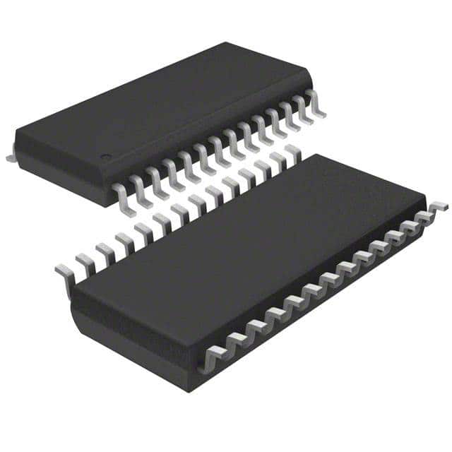
- Part No.:
- DIT4096IPWR
- Manufacturer:
- Texas Instruments
- Category:
- Audio Special Purpose
- Package:
- 28-TSSOP (0.173", 4.40mm Width)
- Datasheet:
-
 DIT4096IPWR.pdf
- Description:
- IC LINE DRIVER 28TSSOP
- Quantity:
- Payment:

- Shipping:

Inventory:1,063
Please send an inquiry. Send us your inquiry, and we will respond immediately.
Product details
Overview
DIT4096IPWR from Texas Instruments is a digital audio transmitter IC compliant with AES-3, IEC-60958, and EIAJ CP1201 standards, supporting sampling rates up to 96kHz, featuring on-chip differential line driver outputs (TX+, TX–), flexible serial audio interface (I²S/Left-/Right-justified), and dual-mode operation (software/hardware control) for integration into professional and consumer audio systems.
For engineers reviewing the DIT4096IPWR datasheet, DIT4096IPWR pinout, DIT4096IPWR application, or DIT4096IPWR equivalent, key selection considerations include AES-3 encoding capability, 96kHz real-time transmission, TSSOP-28 package compatibility, differential output drive strength (±30mA), and dual-control mode flexibility for microcontroller-based or standalone designs.
Technical Context
The DIT4096IPWR implements a full AES-3 encoder with Bi-Phase Mark modulation, multiplexing audio, channel status, user, and validity data into a standardized bitstream. It supports two distinct configuration modes: Software Mode uses a 4-wire serial control port (CS/CCLK/CDIN/CDOUT) to access 8-bit registers and 192-byte channel status buffers; Hardware Mode replaces register access with dedicated pins (FMT0/FMT1/CLK0/CLK1/M/S) for fixed-function setup without firmware.
Its audio serial port operates in Master or Slave mode, accepting 16–24-bit linear PCM in I²S, Left-Justified, or Right-Justified formats, synchronized to SYNC (frame rate = fS) and SCLK (up to 12.5MHz). The integrated differential line driver delivers compliant output levels (VOH = VDD – 0.4V, VOL = 0.4V) with ±30mA drive capability, suitable for transformer-coupled twisted-pair or optical transmission paths.
Key Specifications
| Parameter | Value and Actual Design Meaning |
|---|---|
| AES-3 Compliance | Fully complies with AES-3, IEC-60958, and EIAJ CP1201 standards for professional/consumer digital audio interconnect. |
| Max Sampling Rate | 96kHz - enables high-resolution audio transmission including DVD-Audio and studio-grade recording workflows. |
| Master Clock Input | Supports 256fS, 384fS, or 512fS (e.g., 24.576MHz at 96kHz) - ensures precise timing alignment with external audio clocks. |
| Differential Output Drive | ±30mA into 110Ω load - meets AES-3 electrical requirements for balanced cable transmission up to 10m. |
| Digital I/O Supply Range | VIO = +2.7V to +5.5V - allows direct interfacing with 3.3V or 5V logic domains without level shifters. |
| Core Supply Voltage | VDD = +4.5V to +5.5V - compatible with standard 5V system rails and tolerant of supply ripple. |
| Operating Temperature | –40°C to +85°C - qualified for industrial and broadcast equipment environments. |
| Dynamic Current Draw | 22mA at 96kHz (VDD = +5V) - enables thermal design for continuous high-sample-rate operation in compact enclosures. |
Pinout & Package
TSSOP-28 package (PW suffix), 4.4mm × 9.7mm body, 0.65mm pitch, exposed pad not present. Pin 1 marked by beveled corner; pin count verified per TI SBOS225B datasheet Figure 1 and Table.
| Pin/Terminal | Circuit Role | Design Meaning |
|---|---|---|
| 17, 18 | TX–, TX+ | Differential AES-3 encoded output pair - drives transformer-coupled or optically isolated transmission lines per AES-3 spec. |
| 11, 12, 13 | SCLK, SYNC, SDATA | 3-wire audio serial port interface - accepts I²S/Left-/Right-justified PCM data up to 24-bit/96kHz. |
| 2, 3, 4, 5 | CDOUT, CCLK, CDIN, CS | 4-wire serial control port - enables register read/write and channel status buffer access in Software Mode. |
| 6, 15, 19, 8, 7 | MCLK, RST, VDD, DGND, VIO | Core timing, reset, power, and ground - MCLK must be stable 256fS/384fS/512fS; RST low ≥500ns initiates hardware reset. |
| 25, 27, 26, 28 | BLS, U, V, MODE | Block start sync, user/validity data inputs, and mode select - MODE = 0 enables Software Mode; MODE = 1 enables Hardware Mode. |
Key Features
| Feature | Design Value |
|---|---|
| Dual Control Architecture | Software Mode (register-based via serial port) and Hardware Mode (pin-strapped) - eliminates MCU dependency in cost-sensitive or legacy designs. |
| On-Chip AES-3 Encoder | Performs full frame formatting, channel status/user/validity multiplexing, and Bi-Phase Mark encoding - removes need for external encoding logic. |
| Flexible Audio Format Support | I²S, Left-Justified, Right-Justified (16/18/20/24-bit) - interoperates with TI C5000/C6000 DSPs, Cirrus Logic codecs, and AKM ADCs. |
| Differential Line Driver | Integrated 110Ω-output impedance driver with ±30mA capability - meets AES-3 voltage swing (2–7V p-p) without external amplifiers. |
| Channel Status Management | 192-byte buffer (Software Mode) or dedicated pins (CSS/COPY/L/AUDIO/EMPH in Hardware Mode) - enables real-time metadata updates for copy protection and format signaling. |
| Low-Power Operation | 2μA power-down current (VDD = +5V) - supports energy-efficient standby in battery-backed broadcast monitors or portable recorders. |
Applications
| Digital Mixing Consoles | Digital Audio Workstations |
|---|---|
Use Scenario: Routing multi-channel PCM streams from FPGA-based mixer engines to AES-3 distribution backplanes. IC Role / Device Role / Timing Role: Digital audio transmitter converting parallel audio bus data into serialized, standards-compliant AES-3 bitstream with embedded channel status. Use Value: Enables deterministic latency (<1 frame) and jitter-free transmission across 32-channel analog-to-digital conversion chains using single TSSOP-28 device per stereo pair. | Use Scenario: Connecting high-fidelity audio interfaces (e.g., RME Fireface) to monitoring systems requiring AES-3 input synchronization. IC Role / Device Role / Timing Role: Standards-compliant transmitter ensuring bit-accurate delivery of 24-bit/96kHz PCM with validated channel status flags for sample rate and word length. Use Value: Guarantees interoperability with Pro Tools HDX, Nuendo, and Pyramix systems via native AES-3 handshake and CRC generation in Professional Mode. |
| Broadcast Studio Equipment | A/V Receivers |
Use Scenario: Embedding audio from SDI-embedded sources into AES-3 distribution networks for OB van routing matrices. IC Role / Device Role / Timing Role: AES-3 encoder with CRC generation and transformer-coupled differential outputs - maintains SMPTE 259M timing integrity during format conversion. Use Value: Delivers EIAJ CP1201 compliance required for NHK and BBC broadcast certification, including pre-emphasis flagging and generation status bits. | Use Scenario: Accepting SPDIF coaxial input from Blu-ray players and retransmitting as AES-3 to external DACs or powered speakers. IC Role / Device Role / Timing Role: Digital audio transmitter supporting consumer-mode channel status (PRO=0, COPY=1) and mono/stereo auto-detection via BLS signal. Use Value: Enables seamless passthrough of Dolby TrueHD and DTS-HD MA bitstreams while maintaining lip-sync accuracy through fixed-latency pipeline. |
Equivalent & Alternatives
The following parts are listed as comparable options for similar digital audio transmitter applications.
| Alternative Part | Technical Difference | Application Difference | Selection Advice |
|---|---|---|---|
| AK4117VN | Supports 192kHz max sampling rate; includes integrated PLL for clock recovery; requires external line driver. | Targeted at high-end DACs needing ultra-low-jitter clock regeneration; lacks on-chip differential driver. | Select AK4117VN when system-level jitter budget demands <100fs RMS and external transformer coupling is acceptable. |
| CS8416-CQZ | Includes S/PDIF receiver + AES-3 transmitter; supports 100kHz sampling; no hardware mode; 28-QSOP package. | Designed for bidirectional digital audio routing (receiver + transmitter); higher pin count limits PCB space efficiency. | Choose CS8416-CQZ only if dual-role functionality (receive + transmit) is required and board area permits larger QSOP footprint. |
Compared with AK4117VN and CS8416-CQZ, the DIT4096IPWR provides unique value in cost-constrained, single-function AES-3 transmission applications where integrated differential drive, dual-control mode flexibility, and 96kHz support reduce BOM count and firmware complexity - especially in mixing consoles and broadcast gear where transformer isolation is standard.
Availability
DIT4096IPWR is available at Aetrix Electronics and suitable for digital mixing consoles, broadcast studio equipment, and A/V receivers requiring stable component supply, long-term lifecycle assurance, and traceable sourcing for production programs.
Supply support for DIT4096IPWR includes scheduled delivery planning, volume procurement assistance, BOM continuity management, traceable sourcing, and lifecycle availability coordination for OEM customers, industrial embedded developers, connected-device designers, and electronics production programs.
Manufacturer
Texas Instruments is a global semiconductor leader specializing in analog, embedded processing, and digital signal technologies, with over 50 years of innovation in precision analog ICs and audio solutions.
The DIT4096IPWR belongs to TI's professional audio interface product line, engineered specifically for robust, standards-compliant digital audio transmission in broadcast, studio, and high-fidelity consumer equipment where AES-3 interoperability and reliability are critical.
FAQ
What is the maximum sampling frequency supported by the DIT4096IPWR?
The DIT4096IPWR supports a maximum sampling frequency of 96kHz, as confirmed in the General Description and Electrical Characteristics sections of the TI SBOS225B datasheet. This enables high-resolution audio transmission for applications such as DVD-Audio playback, digital audio workstations, and broadcast-grade recording systems. The device maintains full AES-3 compliance and accurate channel status encoding at this rate, with master clock requirements scaling to 24.576MHz (512×fS).
Does the DIT4096IPWR include an integrated line driver?
Yes, the DIT4096IPWR includes an on-chip differential line driver with outputs TX+ (pin 18) and TX– (pin 17). As specified in the Electrical Characteristics table, it delivers ±30mA drive capability into a 110Ω load, meeting AES-3 electrical requirements for transformer-coupled twisted-pair cabling. This eliminates the need for external driver circuitry in most professional and consumer implementations of the DIT4096IPWR.
Can the DIT4096IPWR operate without a microcontroller?
Yes, the DIT4096IPWR supports Hardware Mode (MODE = 1) with dedicated configuration pins (FMT0/FMT1/CLK0/CLK1/M/S), enabling full functionality without any microcontroller or firmware. In this mode, audio format, master clock rate, and master/slave operation are set via hardwired logic levels - making the DIT4096IPWR suitable for fixed-function audio gear like legacy A/V receivers or broadcast encoders where MCU resources are unavailable or undesirable.
What audio data formats does the DIT4096IPWR support?
The DIT4096IPWR supports I²S, Left-Justified, and Right-Justified audio data formats at word lengths of 16, 18, 20, or 24 bits. In Software Mode, format selection is programmable via Control Register 03H; in Hardware Mode, FMT0/FMT1 pins select among four predefined variants (e.g., 24-bit I²S or 16-bit Right-Justified). All formats are validated for 96kHz operation and maintain strict timing alignment per the SYNC and SCLK specifications in the DIT4096IPWR datasheet.
How is channel status data handled in Hardware Mode for the DIT4096IPWR?
In Hardware Mode, channel status data for the DIT4096IPWR is input either through dedicated pins (CSS = 0: COPY, L, AUDIO, EMPH) or serially via the C input (CSS = 1). When CSS = 0, these pins directly map to specific AES-3 channel status bits (e.g., PRO, COPY, pre-emphasis); when CSS = 1, all 192 bits are clocked serially on SYNC edges. Both methods are fully documented in Tables VI and Figure 5 of the DIT4096IPWR datasheet and require no software intervention.
DIT4096IPWR Specifications
- Product attributes
- Attribute value
- Manufacturer:
- Texas Instruments
- Series:
- -
- Package/Case:
- 28-TSSOP (0.173", 4.40mm Width)
- Packaging:
- Tape & Reel (TR)
- Product Status:
- Active
- Function:
- Line Driver
- Applications:
- Pre-Amplifier, Professional Audio
- Number of Channels:
- 1
- Interface:
- SPI
- Voltage - Supply:
- 4.5V ~ 5.5V
- Operating Temperature:
- -40°C ~ 85°C (TA)
- Specifications:
- Differential Output
- Mounting Type:
- Surface Mount
- Grade:
- -
DIT4096IPWR FAQ
1.How can I place an order for DIT4096IPWR through Aetrix?
Please submit a Request for Quotation (RFQ) for DIT4096IPWR on Aetrix. Our sales agent will provide a competitive quotation and guide you through the order confirmation once you accept the terms.
2.Are the price and stock information for DIT4096IPWR reliable?
The price and inventory of DIT4096IPWR are updated periodically and may fluctuate due to market conditions. Stock and pricing data are typically refreshed every 24 hours. Quotation validity for DIT4096IPWR is usually 5 days.
3.What payment methods are accepted for DIT4096IPWR?
We accept Wire Transfer, PayPal, Credit Card, Western Union, MoneyGram, and Escrow for DIT4096IPWR transactions.
Note: Certain payment methods may incur a processing fee.
4.How is shipping managed for DIT4096IPWR?
DIT4096IPWR orders can be shipped via leading logistics carriers, including DHL, UPS, FedEx, TNT, or Registered Mail.
Once your DIT4096IPWR order is processed, you will receive an email with the shipment details and tracking number.
Note: Tracking information may take up to 24 hours to appear. Express delivery typically takes 3–5 business days.
5.How can I obtain technical support or documentation for DIT4096IPWR?
For technical support, including DIT4096IPWR datasheets, pinout diagrams, or application guidance, please contact our engineering support team. They can provide detailed documentation and assistance for your DIT4096IPWR requirements.
6.How does Aetrix verify that DIT4096IPWR is sourced from the original manufacturer or authorized distributors?
All DIT4096IPWR products on Aetrix are procured from qualified distributors and authorized channels. Our dedicated quality assurance team conducts strict verification, including traceability checks and, if necessary, third-party testing. This ensures that DIT4096IPWR meets industry standards.
7.What is the process for return or replacement of DIT4096IPWR?
All DIT4096IPWR units undergo pre-shipment inspection (PSI). If there is an issue with DIT4096IPWR, returns or replacements are accepted under the following conditions:
1.Quantity discrepancies, incorrect items, or visible external defects (such as breakage or corrosion), acknowledged by Aetrix.
2.The issue is reported within 90 days of delivery.
3.The DIT4096IPWR part is unused and in its original packaging.
Return procedure for DIT4096IPWR:
1.Submit a request within 90 days.
2.Obtain a Return Material Authorization (RMA) from Aetrix.
DIT4096IPWR Tags

-
SA571DR2G
onsemi

-
ADAU7002ACBZ-R7
Analog Devices Inc.

-
DRV135UA/2K5
Texas Instruments

-
DRV134UA/1K
Texas Instruments

-
DRV134PA
Texas Instruments
-
DRV134UA
Texas Instruments
-
DRV135UA
Texas Instruments
-
SA572DR2G
onsemi
-
PGA2311U/1K
Texas Instruments

-
SI8244BB-D-IS1R
Skyworks Solutions Inc.

-
CS8416K-CZZR
Cirrus Logic Inc.

-
SRC4392IPFBR
Texas Instruments
Tech Hub

A practical engineering guide to 3.3V and 5V logic compatibility, input thresholds, resistor dividers, translator ICs, MOSFET level shifting, I2C pull-ups, timing limits and power-sequencing risks.

The 74HC595 uses push-pull logic outputs, while the TPIC6B595 uses 50 V open-drain DMOS sinks for higher-power loads. This guide compares timing, current limits, 3.3 V interfacing, load wiring, thermal…

The 74HC595 converts serial data into eight stable parallel outputs. This guide covers pin functions, shift and storage timing, OE and MR behavior, drive-current limits, cascading, voltage compatibilit…

A technical comparison of level-sensitive latches and edge-triggered flip-flops, covering timing windows, setup and hold limits, master–slave operation, time borrowing, race-through, HDL inference and…

A D latch stores one bit while Enable controls when data can pass. This reference covers gate-level operation, truth tables, transparency, setup and hold timing, LE versus OE, common ICs and practical …

An SR latch stores one bit through cross-coupled feedback. This engineering reference covers NOR and NAND implementations, truth tables, forbidden-state recovery, gated operation, switch debouncing, fa…

Latch circuits retain one bit through feedback. This technical reference covers SR and D latches, truth tables, transparency, timing limits, latch-versus-flip-flop behavior, applications and common log…

An engineering guide to LED driver operation, constant-current and constant-voltage outputs, linear and switching topologies, dimming, IC selection, calculations, replacement compatibility, and fault c…

Operational amplifier guide covering op amp basics, feedback, ideal vs real op amps, common configurations, buffer circuits, offset, bias current, gain-bandwidth, slew rate, rail-to-rail limits and sel…

Jumper cables guide covering safe connection order, red and black clamp placement, final ground connection, cable gauge, length, clamp quality, copper vs CCA cables, jump starter comparison and battery…


