
 My Inquiry
 My Account


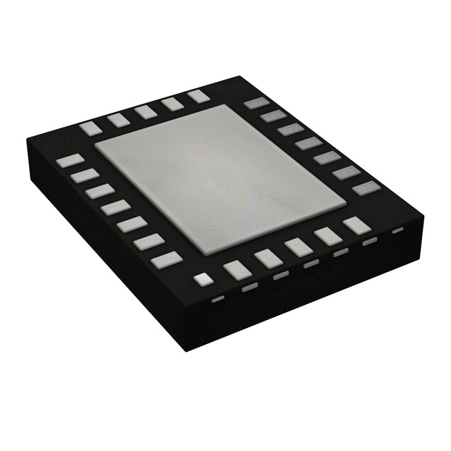
Texas Instruments DP83825IRMQR
- Part No.:
- DP83825IRMQR
- Manufacturer:
- Texas Instruments
- Category:
- Drivers, Receivers, Transceivers
- Package:
- 24-WFQFN Exposed Pad
- Datasheet:
-
 DP83825IRMQR.pdf
- Description:
- IC TXRX FULL/HALF 1/1 24WQFN
- Quantity:
- Payment:

- Shipping:

Inventory:4,510
Please send an inquiry. Send us your inquiry, and we will respond immediately.
Product details
Overview
DP83825IRMQR from Texas Instruments is a single-port 10/100BASE-TX and 10BASE-Te Ethernet Physical Layer transceiver in a 3mm × 3mm WQFN-24 package, supporting RMII MAC interface (leader/follower mode), integrated MDI/MAC termination resistors, and cable reach up to 150 meters over CAT5e. It operates from a single 3.3V supply with I/O voltage flexibility (1.8V or 3.3V) and delivers ultra-low power consumption (<127 mW in optimized mode).
For engineers reviewing the DP83825IRMQR datasheet, DP83825IRMQR pinout, DP83825IRMQR application, or DP83825IRMQR equivalent, key selection criteria include RMII timing compliance (20 ns clock period), EEE IEEE 802.3az support for legacy MACs, Wake-on-LAN capability, integrated cable diagnostics, and thermal performance (RθJA = 53.5°C/W) in space-constrained industrial edge nodes.
Technical Context
The DP83825IRMQR implements mixed-signal equalization and data recovery to sustain robust 100BASE-TX operation over 150 m CAT5e cable. Its RMII interface supports both leader (50 MHz output) and follower (25 MHz input) clocking modes, with automatic VDDIO/AVDD configuration enabling seamless 1.8V or 3.3V I/O interfacing without strap changes.
It integrates Auto-MDIX resolution per IEEE 802.3 Clause 40.8.2, independent of Auto-Negotiation, and provides three hardware-configurable low-power states-Active Sleep (11 mA), Deep Power Down (3.5 mA), and IEEE Power Down (4 mA)-alongside Energy Efficient Ethernet with LPI entry/exit timing (Ts = 210 µs, Tw_sys_tx = 36 µs).
Key Specifications
| Parameter | Value and Actual Design Meaning |
|---|---|
| Media Standards | IEEE 802.3 100BASE-TX and 10BASE-Te compliant; supports full-duplex operation on twisted-pair media |
| MAC Interface | RMII with configurable leader/follower mode; 20 ns clock period, 35–65% duty cycle, 4 ns setup/2 ns hold timing |
| Power Consumption | <127 mW typical in power-optimized mode; 15.5 mA AVDD current in 100BASE-TX EEE mode |
| Cable Reach | Up to 150 meters over CAT5e cable using voltage-mode line driver and adaptive equalization |
| Operating Temperature | –40°C to +85°C ambient; qualified for industrial environments with RθJB = 2.3°C/W board-level thermal resistance |
| ESD Robustness | ±5 kV HBM on MDI pins (TD±, RD±); ±1.5 kV HBM on all other pins per ANSI/ESDA/JEDEC JS-001 |
| Supply Voltages | Single 3.3V analog supply (AVDD); flexible I/O supply (VDDIO = 1.8V or 3.3V) with auto-detection |
Pinout & Package
DP83825IRMQR is housed in a thermally enhanced 3.00 mm × 3.00 mm WQFN-24 package with exposed thermal pad (DAP = GND). The 24-pin layout supports compact PCB routing and efficient heat dissipation via bottom-side thermal vias.
| Pin/Terminal | Circuit Role | Design Meaning |
|---|---|---|
| TX_EN (Pin 1) | RMII Transmit Enable | Active-high signal synchronized to TX_CLK rising edge; indicates valid TX_D[1:0] data presence |
| 50MHzOut/LED2 (Pin 2) | RMII Clock Output / LED Driver | Default 50 MHz output in leader mode; configurable as GPIO or LED2 indicator |
| INTR/PWRDN (Pin 3) | Interrupt / Power-Down Control | Open-drain output with 9.5 kΩ internal pull-up; active-low assertion triggers power-down or signals interrupt |
| LED0 (Pin 4) | Link/Activity Indicator | 3.3V-tolerant LED driver independent of VDDIO; blinks on TX/RX activity, stays ON during link-up |
| RST_N (Pin 5) | Active-Low Reset Input | Minimum 25 µs pulse resets all registers and rescans strap pins; 3.3V-tolerant regardless of VDDIO level |
| VDDA3V3 (Pin 6) | Analog Supply | 3.3V input for analog PHY blocks; requires local 0.1 µF + 10 µF decoupling per TI layout guidelines |
| RD_M / RD_P (Pins 7, 8) | Differential Receive Inputs | Auto-configured for 10BASE-Te or 100BASE-TX signaling; accept transformer-coupled MDI signals |
| TD_M / TD_P (Pins 10, 11) | Differential Transmit Outputs | Voltage-mode line drivers with programmable amplitude; connect directly to transformer center taps |
| XI/50MHzIn (Pin 13) | Reference Clock Input | Accepts 25 MHz ±50 ppm crystal (leader) or 50 MHz ±50 ppm CMOS oscillator (follower) |
| RBIAS (Pin 14) | Bias Resistor Terminal | Requires external 6.49 kΩ ±1% resistor to GND for internal bias current generation |
| MDIO / MDC (Pins 15, 16) | SMI Management Interface | MDIO bidirectional with 10 kΩ internal pull-up; MDC supports up to 24 MHz clock for register access |
| RX_D0 / RX_D1 (Pins 18, 17) | RMII Receive Data | Valid symbols presented synchronous to reference clock when CRS_DV is asserted |
| VDDIO (Pin 19) | I/O Supply Voltage | Configurable 1.8V or 3.3V rail; powers RMII, SMI, and LED pins; auto-detected by internal logic |
| CRS_DV (Pin 20) | Carrier Sense / Receive Valid | Combined RMII carrier detect and receive data valid signal; asserted high during packet reception |
| RX_ER (Pin 22) | Receive Error Flag | Asserted high synchronously to reference clock edge when error symbol detected; optional for RMII MAC |
| TX_D0 / TX_D1 (Pins 23, 24) | RMII Transmit Data | 2-bit parallel data from MAC, sampled on rising edge of reference clock in leader/follower mode |
Key Features
| Feature | Design Value |
|---|---|
| Integrated MDI & MAC Termination Resistors | Eliminates 12 external 49.9 Ω resistors, reducing BOM count and PCB area in RMII-based designs |
| Programmable Energy Saving Modes | Four distinct low-power states-including EEE IEEE 802.3az, Active Sleep, and Deep Power Down-with sub-5 mA total current draw in deepest state |
| On-Chip Cable Diagnostics | Real-time open/short detection and length estimation without external test equipment; supports field maintenance and remote troubleshooting |
| Wake-on-LAN (WoL) Support | Enables system wake from deep sleep upon receipt of magic packet or pattern match; uses dedicated hardware filtering independent of host CPU |
| Auto-MDIX Resolution | Hardware-accelerated polarity correction eliminates need for crossover cables or manual port configuration in unmanaged deployments |
| RMII Back-to-Back Repeater Mode | Operates as unmanaged repeater without register programming-ideal for simple hub-like applications with minimal firmware overhead |
Applications
| IP Camera Systems | Industrial HMIs |
|---|---|
Use Scenario: Compact, fanless IP cameras deployed in building automation require reliable 100 Mbps connectivity with minimal power draw and thermal footprint. IC Role / Device Role / Timing Role: DP83825IRMQR serves as the physical layer interface between SoC's RMII controller and RJ-45 magnetics, handling signal conditioning, auto-negotiation, and EEE-compliant idle management. Use Value: 150 m cable reach enables flexible camera placement; <127 mW power enables passive PoE compatibility; integrated terminations reduce component count by ≥12 parts. |
Use Scenario: Human-machine interface panels in factory automation demand robust Ethernet connectivity across wide temperature ranges and noisy EMI environments. IC Role / Device Role / Timing Role: DP83825IRMQR acts as the hardened PHY layer, providing Auto-MDIX, cable diagnostics, and –40°C to +85°C operation for deterministic link establishment. Use Value: ±5 kV MDI ESD rating ensures reliability in industrial settings; built-in self-test (BIST) enables runtime health monitoring; RMII timing compliance guarantees interoperability with ARM Cortex-A/M-based display controllers. |
| Electronic Point-of-Sale Terminals | Motor Drive Controllers |
Use Scenario: Compact, cost-sensitive POS terminals require fast Ethernet boot, low standby power, and LED status feedback without external components. IC Role / Device Role / Timing Role: DP83825IRMQR functions as the complete PHY solution-providing LED0/LED2 drivers, WoL wake capability, and 25 ms power-up-to-FLP timing for rapid network initialization. Use Value: 3.3V-tolerant LED outputs eliminate level-shifting; 1500 ms FLP burst time ensures compatibility with legacy switches; 1.8V I/O support enables direct connection to low-voltage application processors. |
Use Scenario: Distributed motor control nodes in servo drives use Ethernet for real-time command updates and fault reporting under high EMI conditions. IC Role / Device Role / Timing Role: DP83825IRMQR provides deterministic latency (105 ns Tx, 325 ns Rx at 100 Mbps) and jitter-controlled 50 MHz RMII clock output for synchronized motion control loops. Use Value: 450 ps long-term jitter meets industrial Ethernet timing budgets; thermal resistance (RθJB = 2.3°C/W) enables conduction-cooled mounting on metal enclosures; cable diagnostics aid in field wiring validation. |
Equivalent & Alternatives
The following parts are listed as comparable options for similar Ethernet PHY applications.
| Alternative Part | Technical Difference | Application Difference | Selection Advice |
|---|---|---|---|
| DP83822HFRMQR | Supports RGMII and fiber interfaces; wider temperature range (–40°C to +105°C); larger 5 mm × 5 mm VQFN-32 package | Required for RGMII-based SoCs or extended-temperature motor drives; not pin-compatible with DP83825IRMQR | Select DP83822HFRMQR only when RGMII interface or >85°C operation is mandatory; layout redesign needed due to different pin count and size. |
| LAN8720AI-CP | QFN-24, 3.3V-only I/O (no 1.8V support); lacks EEE for legacy MACs and active sleep mode; higher typical power (160 mW) | Suitable for cost-sensitive consumer-grade devices where EEE and ultra-low standby are non-critical | Choose LAN8720AI-CP for simpler, lower-cost designs without advanced power management; verify RMII timing margins as tsetup is 5 ns vs. DP83825IRMQR's 4 ns. |
Compared with DP83825IRMQR, DP83822HFRMQR adds RGMII and extended temperature but increases board area and cost, while LAN8720AI-CP reduces feature set and power efficiency to meet budget constraints-making DP83825IRMQR the optimal balance of size, power, and industrial functionality.
Availability
DP83825IRMQR is available at Aetrix Electronics and suitable for IP camera systems, industrial HMIs, and electronic point-of-sale terminals requiring stable component supply, long-term industrial lifecycle support, and guaranteed traceable sourcing.
Supply support for DP83825IRMQR includes scheduled delivery planning, volume procurement assistance, BOM continuity management, traceable sourcing, and lifecycle availability coordination for OEM customers, industrial embedded developers, connected-device designers, and electronics production programs.
Manufacturer
Texas Instruments is a global semiconductor company specializing in analog, embedded processing, and connectivity solutions, with leadership in industrial, automotive, and communications infrastructure markets.
The DP83825IRMQR belongs to TI's low-power Ethernet PHY product line, engineered specifically for space-constrained, thermally demanding industrial edge nodes that require robust 10/100 Mbps connectivity with minimal power and component count.
FAQ
What is the maximum cable length supported by the DP83825IRMQR?
The DP83825IRMQR supports up to 150 meters of CAT5e twisted-pair cable for both 100BASE-TX and 10BASE-Te operation. This reach is achieved through adaptive equalization and voltage-mode line driving, validated per IEEE 802.3 specifications. Performance remains stable across the full –40°C to +85°C operating temperature range, making DP83825IRMQR suitable for long-drop industrial Ethernet deployments.
Does the DP83825IRMQR support both 1.8V and 3.3V I/O interfaces simultaneously?
No-the DP83825IRMQR supports either 1.8V or 3.3V I/O operation, selected automatically based on the voltage applied to the VDDIO pin. When VDDIO = 1.8V, RMII, SMI, and LED pins operate at 1.8V logic levels; when VDDIO = 3.3V, they operate at 3.3V. The device does not support mixed-voltage I/O domains, and the 3.3V-tolerant LED0/RST_N pins remain at 3.3V regardless of VDDIO setting.
How does the DP83825IRMQR implement Energy Efficient Ethernet for legacy MACs?
The DP83825IRMQR supports EEE IEEE 802.3az for legacy MACs lacking native LPI signaling by enabling "EEE for legacy MAC" mode via register configuration (EEECFG3 bits 0 and 3 cleared). In this mode, the PHY autonomously enters Low Power Idle during traffic gaps, using internal timers rather than waiting for MAC-initiated LPI requests-ensuring power savings without MAC firmware changes.
Can the DP83825IRMQR operate as an unmanaged repeater without software configuration?
Yes-the DP83825IRMQR supports RMII back-to-back repeater mode in unmanaged operation. When configured via strap pins (RST_N and LED0 held low during power-up), it functions as a hardware repeater without register writes or host processor involvement. This mode is ideal for simple Ethernet hubs or daisy-chained node expansion where minimal firmware overhead is required.
What thermal design considerations apply to the DP83825IRMQR in high-density layouts?
The DP83825IRMQR features a thermal pad (DAP = GND) and low junction-to-board resistance (RθJB = 2.3°C/W). For reliable operation at full load in enclosed industrial enclosures, TI recommends ≥6 thermal vias (0.3 mm diameter) under the DAP connected to a solid internal ground plane. Board-level thermal simulation should target ≤85°C case temperature, especially when operating continuously at 100BASE-TX with EEE disabled.
DP83825IRMQR Specifications
- Product attributes
- Attribute value
- Manufacturer:
- Texas Instruments
- Series:
- -
- Package/Case:
- 24-WFQFN Exposed Pad
- Packaging:
- Tape & Reel (TR)
- Product Status:
- Active
- Type:
- Transceiver
- Protocol:
- Ethernet, IEEE 802.3
- Number of Drivers/Receivers:
- 1/1
- Duplex:
- Full, Half
- Receiver Hysteresis:
- -
- Data Rate:
- 10Mbps, 100Mbps
- Voltage - Supply:
- 1.62V ~ 1.98V, 3V ~ 3.6V
- Operating Temperature:
- -40°C ~ 85°C (TA)
- Grade:
- -
- Qualification:
- -
- Mounting Type:
- Surface Mount
- Supplier Device Package:
- 24-WQFN (3x3)
DP83825IRMQR FAQ
1.How can I place an order for DP83825IRMQR through Aetrix?
Please submit a Request for Quotation (RFQ) for DP83825IRMQR on Aetrix. Our sales agent will provide a competitive quotation and guide you through the order confirmation once you accept the terms.
2.Are the price and stock information for DP83825IRMQR reliable?
The price and inventory of DP83825IRMQR are updated periodically and may fluctuate due to market conditions. Stock and pricing data are typically refreshed every 24 hours. Quotation validity for DP83825IRMQR is usually 5 days.
3.What payment methods are accepted for DP83825IRMQR?
We accept Wire Transfer, PayPal, Credit Card, Western Union, MoneyGram, and Escrow for DP83825IRMQR transactions.
Note: Certain payment methods may incur a processing fee.
4.How is shipping managed for DP83825IRMQR?
DP83825IRMQR orders can be shipped via leading logistics carriers, including DHL, UPS, FedEx, TNT, or Registered Mail.
Once your DP83825IRMQR order is processed, you will receive an email with the shipment details and tracking number.
Note: Tracking information may take up to 24 hours to appear. Express delivery typically takes 3–5 business days.
5.How can I obtain technical support or documentation for DP83825IRMQR?
For technical support, including DP83825IRMQR datasheets, pinout diagrams, or application guidance, please contact our engineering support team. They can provide detailed documentation and assistance for your DP83825IRMQR requirements.
6.How does Aetrix verify that DP83825IRMQR is sourced from the original manufacturer or authorized distributors?
All DP83825IRMQR products on Aetrix are procured from qualified distributors and authorized channels. Our dedicated quality assurance team conducts strict verification, including traceability checks and, if necessary, third-party testing. This ensures that DP83825IRMQR meets industry standards.
7.What is the process for return or replacement of DP83825IRMQR?
All DP83825IRMQR units undergo pre-shipment inspection (PSI). If there is an issue with DP83825IRMQR, returns or replacements are accepted under the following conditions:
1.Quantity discrepancies, incorrect items, or visible external defects (such as breakage or corrosion), acknowledged by Aetrix.
2.The issue is reported within 90 days of delivery.
3.The DP83825IRMQR part is unused and in its original packaging.
Return procedure for DP83825IRMQR:
1.Submit a request within 90 days.
2.Obtain a Return Material Authorization (RMA) from Aetrix.
DP83825IRMQR Tags

-
ATA6561-GAQW-N
Microchip Technology

-
ATA6561-GBQW-N
Microchip Technology

-
AM26LS32ACDR
Texas Instruments

-
SP485CN-L/TR
MaxLinear, Inc.
-
SP485EN-L/TR
MaxLinear, Inc.
-
SP485EEN-L/TR
MaxLinear, Inc.
-
SP485ECN-L/TR
MaxLinear, Inc.
-
THVD1400DR
Texas Instruments
-
AM26C31IDR
Texas Instruments

-
TLIN1021ADRQ1
Texas Instruments
-
MAX232IDR
Texas Instruments
-
AM26C32IDR
Texas Instruments
Tech Hub

A practical engineering guide to 3.3V and 5V logic compatibility, input thresholds, resistor dividers, translator ICs, MOSFET level shifting, I2C pull-ups, timing limits and power-sequencing risks.

The 74HC595 uses push-pull logic outputs, while the TPIC6B595 uses 50 V open-drain DMOS sinks for higher-power loads. This guide compares timing, current limits, 3.3 V interfacing, load wiring, thermal…

The 74HC595 converts serial data into eight stable parallel outputs. This guide covers pin functions, shift and storage timing, OE and MR behavior, drive-current limits, cascading, voltage compatibilit…

A technical comparison of level-sensitive latches and edge-triggered flip-flops, covering timing windows, setup and hold limits, master–slave operation, time borrowing, race-through, HDL inference and…

A D latch stores one bit while Enable controls when data can pass. This reference covers gate-level operation, truth tables, transparency, setup and hold timing, LE versus OE, common ICs and practical …

An SR latch stores one bit through cross-coupled feedback. This engineering reference covers NOR and NAND implementations, truth tables, forbidden-state recovery, gated operation, switch debouncing, fa…

Latch circuits retain one bit through feedback. This technical reference covers SR and D latches, truth tables, transparency, timing limits, latch-versus-flip-flop behavior, applications and common log…

An engineering guide to LED driver operation, constant-current and constant-voltage outputs, linear and switching topologies, dimming, IC selection, calculations, replacement compatibility, and fault c…

Operational amplifier guide covering op amp basics, feedback, ideal vs real op amps, common configurations, buffer circuits, offset, bias current, gain-bandwidth, slew rate, rail-to-rail limits and sel…

Jumper cables guide covering safe connection order, red and black clamp placement, final ground connection, cable gauge, length, clamp quality, copper vs CCA cables, jump starter comparison and battery…


