
 My Inquiry
 My Account


Texas Instruments DRV2625YFFT
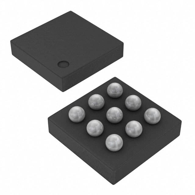
- Part No.:
- DRV2625YFFT
- Manufacturer:
- Texas Instruments
- Category:
- Motor Drivers, Controllers
- Package:
- 9-UFBGA, DSBGA
- Datasheet:
-
 DRV2625YFFT.pdf
- Description:
- IC MOTOR DRIVER 2.7V-5.5V 9DSBGA
- Quantity:
- Payment:

- Shipping:

Inventory:4,567
Please send an inquiry. Send us your inquiry, and we will respond immediately.
Product details
Overview
DRV2625YFFT from Texas Instruments is an ultra-low-power closed-loop haptic driver supporting both LRA and ERM actuators, featuring automatic resonance tracking (±1 Hz resolution), 1.55 µA standby current at 3.6 V, I²C-controlled playback engine, and integrated Immersion TouchSense® 2200 waveform library - deployed in mobile touch feedback and wearable device alerts.
For engineers reviewing the DRV2625YFFT datasheet, DRV2625YFFT pinout, DRV2625YFFT application, or DRV2625YFFT equivalent, key selection criteria include closed-loop LRA frequency range (45–300 Hz), 9-pin DSBGA package (1.498 mm × 1.361 mm), shutdown current <180 nA, real-time playback (RTP) mode latency <1 ms, and resistance-based actuator diagnostics.
Technical Context
The DRV2625YFFT implements a proprietary smart-loop architecture with real-time back-EMF detection for automatic resonance tracking and level calibration. It supports dual-mode operation: closed-loop for precise LRA control (with auto-braking and overdrive) and configurable open-loop (sine/square waveforms, OL_LRA_PERIOD programmable).
Its I²C interface (400 kHz compliant) controls a 1 kB internal RAM waveform sequencer and integrates a 1.8 V regulator (REG pin), NRST-triggered shutdown, and TRIG/INTZ multi-function pin for hardware triggering or interrupt reporting - all operating from 2.7 V to 5.5 V supply with thermal protection and short-circuit detection.
Key Specifications
| Parameter | Value and Actual Design Meaning |
|---|---|
| Supply Voltage Range | 2.7 V to 5.5 V - enables direct integration with single-cell Li-ion or Li-poly battery systems without external regulation. |
| Standby Current | 1.55 µA at 3.6 V - extends battery life in always-on wearable devices by minimizing quiescent draw during idle periods. |
| Shutdown Current | 105–180 nA - achieves near-zero power consumption when NRST is pulled low, critical for long-term storage or deep-sleep modes. |
| LRA Frequency Range | 45 Hz to 300 Hz - covers full tactile spectrum from subtle notifications to strong alert feedback across consumer LRAs. |
| I²C Clock Speed | 400 kHz - supports fast register configuration and real-time waveform updates without CPU overhead bottlenecks. |
| Startup Latency | <1 ms from trigger to output - ensures immediate tactile response aligned with UI events in mobile and HMI applications. |
| Output Impedance (Standby) | 15 kΩ - prevents unintended actuator excitation and leakage current during inactive states. |
| Load Impedance Range | 8 Ω nominal - matches standard ERM motors and low-Z LRA coils without external impedance matching networks. |
Pinout & Package
DRV2625YFFT uses a 9-pin DSBGA package (1.498 mm × 1.361 mm, 0.4 mm pitch) optimized for space-constrained portable designs. The package features bottom-side solder balls and requires controlled thermal relief on PCB pads per TI SLOS879C layout guidelines.
| Pin/Terminal | Circuit Role | Design Meaning |
|---|---|---|
| VDD | Power supply input | Primary 2.7–5.5 V rail; requires 0.1 µF decoupling capacitor close to pin for stable operation. |
| GND | Ground reference | Common return path for power, analog, and digital domains; must be low-impedance and thermally connected to PCB ground plane. |
| REG | 1.8 V regulator output | Provides regulated 1.8 V for external logic or level-shifting; requires 0.1 µF capacitor and supports up to 10 mA load. |
| OUT+ | Positive differential haptic output | Drives one side of LRA/ERM load; paired with OUT− to deliver bipolar drive voltage up to VDD. |
| OUT− | Negative differential haptic output | Completes differential drive path; enables zero-crossing control and reduces EMI vs single-ended drivers. |
| SDA | I²C data bidirectional line | Open-drain interface compatible with 1.8 V logic; supports standard/fast-mode I²C up to 400 kHz. |
| SCL | I²C clock input | Drives synchronous communication; internal pull-up not provided - external 2.2–10 kΩ pull-up required. |
| TRIG/INTZ | Multi-function trigger/interrupt pin | Configurable as pulse-trigger input (active-high), enable signal, or open-drain interrupt output reporting fault/status. |
| NRST | Hardware reset/shutdown control | Pulling low forces full shutdown (180 nA); floating or tied to VDD enables normal operation with auto-standby transition. |
Key Features
| Feature | Design Value |
|---|---|
| Automatic Resonance Tracking | Locks onto LRA resonant frequency within half-cycle using real-time back-EMF sensing - eliminates manual tuning and maintains peak efficiency across temperature and aging. |
| Built-in TouchSense® 2200 Library | Includes 128 pre-validated waveforms with loopable sequencing - reduces firmware development time and ensures consistent tactile quality across product variants. |
| Resistance-Based Actuator Diagnostics | Detects open-circuit, short-circuit, and measures actual coil impedance (DIAG_Z_RESULT) - enables factory calibration and field-failure logging without external test equipment. |
| SimpleDrive One-Wire Scheme | Accepts single-pulse triggers to play stored effects - simplifies host MCU GPIO usage and removes need for continuous I²C polling or waveform streaming. |
| Drive Compensation Over Battery Discharge | Adjusts output amplitude dynamically as VDD drops from 5.5 V to 2.7 V - maintains consistent haptic intensity without host-level gain correction. |
| Off-Resonance Driving with Auto-Braking | Delivers controlled non-resonant waveforms (e.g., square/sine) while applying closed-loop braking - supports hybrid haptic designs where resonance is undesirable or unavailable. |
Applications
| Mobile Touch Feedback | Fitness Band Alerts |
|---|---|
|
Use Scenario: Simultaneous button press confirmation and system navigation feedback in smartphones and tablets. IC Role / Device Role / Timing Role: Closed-loop LRA driver executing TouchSense® waveforms with sub-1-ms startup latency and automatic resonance tracking. Use Value: Delivers crisp, repeatable tactile response independent of LRA unit-to-unit variation or battery voltage drift - improving perceived UI responsiveness and user satisfaction. |
Use Scenario: Silent vibration alerts for call, message, and workout milestone notifications in compact wearables. IC Role / Device Role / Timing Role: Ultra-low-power haptic controller operating in standby (1.55 µA) between alerts, triggered via TRIG/INTZ pulse. Use Value: Extends 7-day battery life in fitness bands by minimizing active and idle current - enabling all-day haptics without compromising form factor. |
| Remote Control Confirmation | HMI Button Simulation |
|
Use Scenario: Tactile feedback for volume, channel, and menu navigation on IR/RF remotes and wireless mice. IC Role / Device Role / Timing Role: ERM driver using SimpleDrive one-wire triggering and automatic overdrive/braking for clean click sensation. Use Value: Eliminates need for host MCU to generate complex waveforms - reduces firmware complexity and ensures consistent mechanical feel across remote SKUs. |
Use Scenario: Physical button replacement in industrial control panels and automotive infotainment interfaces. IC Role / Device Role / Timing Role: Dual-mode driver supporting both LRA (for soft press) and ERM (for sharp click) with programmable waveform shape selection. Use Value: Enables customizable haptic profiles (sine vs square LRA drive) to match ergonomic requirements and audible noise constraints in enclosed enclosures. |
Equivalent & Alternatives
The following parts are listed as comparable options for similar haptic driver applications.
| Alternative Part | Technical Difference | Application Difference | Selection Advice |
|---|---|---|---|
| DRV2605LRTVT | Higher 2.5 mA quiescent current; no REG pin; lacks automatic resonance reporting and TouchSense® license. | Targeted at cost-sensitive ERM-only designs without closed-loop LRA support or advanced diagnostics. | Select when LRA resonance tracking and ultra-low standby power are not required, and BOM cost is prioritized over feature set. |
| MAX20303EWL+T | Integrated PMIC + haptic driver; 3.5 µA standby; no built-in waveform library; supports only ERM. | Used in space-constrained IoT sensors requiring power management co-location, not pure haptic optimization. | Choose when combining haptics with buck/boost regulation and fuel gauging is needed - not for high-fidelity LRA systems. |
Compared with DRV2625YFFT, DRV2605LRTVT offers lower integration and higher power draw but simpler register mapping, while MAX20303EWL+T trades haptic precision for multi-rail power management - making DRV2625YFFT the optimal choice for battery-powered LRA applications demanding consistency, low power, and licensed waveform content.
Availability
DRV2625YFFT is available at Aetrix Electronics and suitable for mobile phones, wearable fitness bands, and human-machine interface devices requiring stable component supply, long-term lifecycle support, and guaranteed traceability.
Supply support for DRV2625YFFT includes scheduled delivery planning, volume procurement assistance, BOM continuity management, traceable sourcing, and lifecycle availability coordination for OEM customers, industrial embedded developers, connected-device designers, and electronics production programs.
Manufacturer
Texas Instruments is a global semiconductor leader specializing in analog, embedded processing, and connectivity technologies, with decades of expertise in precision power and signal chain solutions.
The DRV2625YFFT belongs to TI's haptic driver product line, engineered specifically for ultra-low-power, closed-loop tactile feedback in battery-operated portable electronics - emphasizing power efficiency, actuator adaptability, and seamless integration with resource-constrained MCUs.
FAQ
What is the primary function of the DRV2625YFFT in a haptic system?
The DRV2625YFFT serves as a closed-loop haptic driver that autonomously manages LRA and ERM actuator performance through real-time back-EMF monitoring, automatic resonance tracking, overdrive, and braking. Unlike open-loop drivers, it relieves the host MCU from waveform timing and amplitude compensation - ensuring consistent tactile output across varying battery voltage, temperature, and actuator tolerances. The DRV2625YFFT executes this using its integrated TouchSense® 2200 library and 1 kB waveform sequencer.
How does the DRV2625YFFT achieve ultra-low-power operation?
The DRV2625YFFT achieves ultra-low-power operation via multiple hardware-enforced states: shutdown mode draws only 105–180 nA when NRST is pulled low; standby mode consumes just 1.55 µA at 3.6 V with automatic transition after inactivity; and intelligent power preservation adjusts drive strength dynamically as VDD declines from 5.5 V to 2.7 V. These features collectively extend battery life in wearables and mobile devices without sacrificing haptic fidelity - a capability confirmed in TI's SLOS879C characterization data.
Can the DRV2625YFFT drive both LRA and ERM actuators interchangeably?
Yes, the DRV2625YFFT supports both LRA and ERM actuators via software-configurable LRA_ERM bit. In LRA mode, it activates closed-loop resonance tracking, waveform shape selection (sine/square), and real-time frequency reporting. In ERM mode, it applies automatic overdrive and braking based on acceleration feedback - eliminating need for custom waveforms per motor. The DRV2625YFFT validates actuator presence and impedance before initialization, ensuring safe operation regardless of type.
What role does the REG pin serve on the DRV2625YFFT?
The REG pin on the DRV2625YFFT outputs a regulated 1.8 V supply derived from VDD, capable of sourcing up to 10 mA. It is intended to power external 1.8 V logic, level shifters, or sensor interfaces - reducing need for a separate LDO in compact designs. A 0.1 µF ceramic capacitor is mandatory at the REG pin per TI SLOS879C layout guidance to ensure stability and transient response. This feature simplifies power architecture in space-constrained applications like earbuds and smartwatches where the DRV2625YFFT is commonly deployed.
Does the DRV2625YFFT require external components for basic operation?
Yes, the DRV2625YFFT requires two mandatory external capacitors: a 0.1 µF ceramic capacitor on VDD (close to the pin) and another 0.1 µF on REG for regulator stability. No external resistors or inductors are needed for core haptic operation. The I²C interface requires external pull-up resistors (2.2–10 kΩ) on SDA/SCL. All other functions - including diagnostics, resonance tracking, and waveform playback - are fully self-contained within the DRV2625YFFT die and its internal ROM/RAM resources.
DRV2625YFFT Specifications
- Product attributes
- Attribute value
- Manufacturer:
- Texas Instruments
- Series:
- -
- Package/Case:
- 9-UFBGA, DSBGA
- Packaging:
- Tape & Reel (TR)
- Product Status:
- Active
- Motor Type - Stepper:
- -
- Motor Type - AC, DC:
- ERM, LRA
- Function:
- Driver - Fully Integrated, Control and Power Stage
- Output Configuration:
- Half Bridge (2)
- Interface:
- I2C
- Technology:
- Power MOSFET
- Step Resolution:
- -
- Applications:
- Haptic Feedback
- Current - Output:
- -
- Voltage - Supply:
- 2.7V ~ 5.5V
- Voltage - Load:
- 2.7V ~ 5.5V
- Operating Temperature:
- -40°C ~ 150°C (TJ)
- Grade:
- -
- Qualification:
- -
- Mounting Type:
- Surface Mount
- Supplier Device Package:
- 9-DSBGA
DRV2625YFFT FAQ
1.How can I place an order for DRV2625YFFT through Aetrix?
Please submit a Request for Quotation (RFQ) for DRV2625YFFT on Aetrix. Our sales agent will provide a competitive quotation and guide you through the order confirmation once you accept the terms.
2.Are the price and stock information for DRV2625YFFT reliable?
The price and inventory of DRV2625YFFT are updated periodically and may fluctuate due to market conditions. Stock and pricing data are typically refreshed every 24 hours. Quotation validity for DRV2625YFFT is usually 5 days.
3.What payment methods are accepted for DRV2625YFFT?
We accept Wire Transfer, PayPal, Credit Card, Western Union, MoneyGram, and Escrow for DRV2625YFFT transactions.
Note: Certain payment methods may incur a processing fee.
4.How is shipping managed for DRV2625YFFT?
DRV2625YFFT orders can be shipped via leading logistics carriers, including DHL, UPS, FedEx, TNT, or Registered Mail.
Once your DRV2625YFFT order is processed, you will receive an email with the shipment details and tracking number.
Note: Tracking information may take up to 24 hours to appear. Express delivery typically takes 3–5 business days.
5.How can I obtain technical support or documentation for DRV2625YFFT?
For technical support, including DRV2625YFFT datasheets, pinout diagrams, or application guidance, please contact our engineering support team. They can provide detailed documentation and assistance for your DRV2625YFFT requirements.
6.How does Aetrix verify that DRV2625YFFT is sourced from the original manufacturer or authorized distributors?
All DRV2625YFFT products on Aetrix are procured from qualified distributors and authorized channels. Our dedicated quality assurance team conducts strict verification, including traceability checks and, if necessary, third-party testing. This ensures that DRV2625YFFT meets industry standards.
7.What is the process for return or replacement of DRV2625YFFT?
All DRV2625YFFT units undergo pre-shipment inspection (PSI). If there is an issue with DRV2625YFFT, returns or replacements are accepted under the following conditions:
1.Quantity discrepancies, incorrect items, or visible external defects (such as breakage or corrosion), acknowledged by Aetrix.
2.The issue is reported within 90 days of delivery.
3.The DRV2625YFFT part is unused and in its original packaging.
Return procedure for DRV2625YFFT:
1.Submit a request within 90 days.
2.Obtain a Return Material Authorization (RMA) from Aetrix.
DRV2625YFFT Tags

-
DRV2603RUNR
Texas Instruments

-
DRV8837CDSGR
Texas Instruments

-
DRV8837DSGR
Texas Instruments
-
DRV8838DSGR
Texas Instruments

-
DRV8839DSSR
Texas Instruments

-
EMC2301-1-ACZL-TR
Microchip Technology
-
DRV8231ADSGR
Texas Instruments

-
EMC2302-2-AIZL-TR
Microchip Technology

-
DRV8800PWPR
Texas Instruments
-
DRV8835DSSR
Texas Instruments

-
EMC2303-1-KP-TR
Microchip Technology

-
DRV8876PWPR
Texas Instruments
Tech Hub

A practical engineering guide to 3.3V and 5V logic compatibility, input thresholds, resistor dividers, translator ICs, MOSFET level shifting, I2C pull-ups, timing limits and power-sequencing risks.

The 74HC595 uses push-pull logic outputs, while the TPIC6B595 uses 50 V open-drain DMOS sinks for higher-power loads. This guide compares timing, current limits, 3.3 V interfacing, load wiring, thermal…

The 74HC595 converts serial data into eight stable parallel outputs. This guide covers pin functions, shift and storage timing, OE and MR behavior, drive-current limits, cascading, voltage compatibilit…

A technical comparison of level-sensitive latches and edge-triggered flip-flops, covering timing windows, setup and hold limits, master–slave operation, time borrowing, race-through, HDL inference and…

A D latch stores one bit while Enable controls when data can pass. This reference covers gate-level operation, truth tables, transparency, setup and hold timing, LE versus OE, common ICs and practical …

An SR latch stores one bit through cross-coupled feedback. This engineering reference covers NOR and NAND implementations, truth tables, forbidden-state recovery, gated operation, switch debouncing, fa…

Latch circuits retain one bit through feedback. This technical reference covers SR and D latches, truth tables, transparency, timing limits, latch-versus-flip-flop behavior, applications and common log…

An engineering guide to LED driver operation, constant-current and constant-voltage outputs, linear and switching topologies, dimming, IC selection, calculations, replacement compatibility, and fault c…

Operational amplifier guide covering op amp basics, feedback, ideal vs real op amps, common configurations, buffer circuits, offset, bias current, gain-bandwidth, slew rate, rail-to-rail limits and sel…

Jumper cables guide covering safe connection order, red and black clamp placement, final ground connection, cable gauge, length, clamp quality, copper vs CCA cables, jump starter comparison and battery…


