
 My Inquiry
 My Account


Texas Instruments DRV8881PRHRR
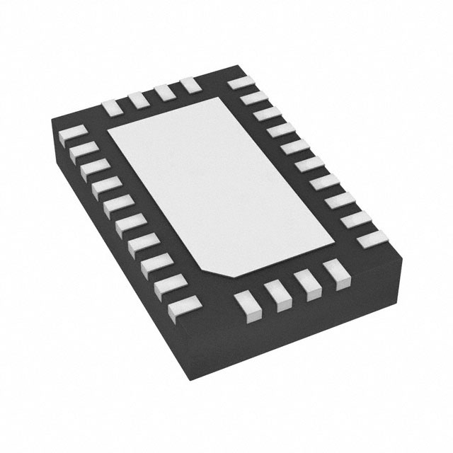
- Part No.:
- DRV8881PRHRR
- Manufacturer:
- Texas Instruments
- Category:
- Motor Drivers, Controllers
- Package:
- 28-WFQFN Exposed Pad
- Datasheet:
-
 DRV8881PRHRR.pdf
- Description:
- IC MTR DRV BIPOLAR 6.5-45V 28QFN
- Quantity:
- Payment:

- Shipping:

Inventory:2,476
Please send an inquiry. Send us your inquiry, and we will respond immediately.
Product details
Overview
DRV8881PRHRR from Texas Instruments is a 28-pin WQFN-packaged dual H-bridge motor driver IC for bipolar stepper and brushed-DC motors, operating from 6.5 V to 45 V, delivering up to 2.5-A peak/1.4-A rms per bridge, with PWM control interface, parallel mode support, and integrated 3.3-V/10-mA LDO regulator - used in video security cameras and multi-function printers.
For engineers reviewing the DRV8881PRHRR datasheet, DRV8881PRHRR pinout, DRV8881PRHRR application, or DRV8881PRHRR equivalent, this page delivers verified electrical specs (RDS(ON) = 330 mΩ HS / 300 mΩ LS at 24 V, 25°C), decay mode configuration (fast/mixed/slow), adaptive blanking time, torque DAC scaling (25–100%), and fault reporting via open-drain nFAULT.
Technical Context
The DRV8881PRHRR implements two independent NMOS H-bridge output stages with integrated current-sense amplifiers, fixed-off-time PWM chopping (10/20/30 µs selectable via TOFF pin), and tri-level decay mode control (ADECAY/BDECAY) for precise winding current regulation. It supports parallel mode (via PARA pin) to combine both bridges for 2.8-A rms output.
Its control architecture uses PWM inputs (AIN1/AIN2/BIN1/BIN2) with internal pulldowns, enabling direct microcontroller interfacing without external logic. Smart tune is excluded - this is the DRV8881P variant, not DRV8881E - and instead offers configurable off-time and torque DAC (TRQ0/TRQ1) for dynamic current scaling without analog reference adjustment.
Key Specifications
| Parameter | Value and Actual Design Meaning |
|---|---|
| Supply Voltage Range | 6.5 V to 45 V - supports wide industrial DC bus voltages including 12 V, 24 V, and 36 V systems without external regulators. |
| Peak Output Current | 2.5 A per H-bridge - sets overcurrent protection trip level (IOCP), limiting transient surge capability during startup or stall. |
| RMS Output Current | 1.4 A per H-bridge (2.8 A in parallel mode) - thermal limit at TA = 25°C with proper PCB ground plane; derates with ambient temperature and layout. |
| High-Side RDS(ON) | 330 mΩ at 24 V, 25°C - determines conduction loss and heating under full-load DC conditions; increases to 440 mΩ at 125°C. |
| Low-Side RDS(ON) | 300 mΩ at 24 V, 25°C - contributes to total bridge on-resistance and impacts efficiency in slow-decay or brake modes. |
| Internal LDO Output | 3.3 V ±0.3 V, 10 mA - powers external logic or sensors; requires 0.47-µF ceramic bypass capacitor on V3P3 to GND. |
| Sleep Current | 28 µA at 24 V, 25°C - enables ultra-low-power standby in battery-backed or energy-sensitive motion systems. |
Pinout & Package
DRV8881PRHRR is housed in a 28-pin WQFN package (5.50 mm × 3.50 mm) with exposed thermal pad (connected to GND). The package supports high-power dissipation via PCB copper area under the pad and is RoHS-compliant.
| Pin/Terminal | Circuit Role | Design Meaning |
|---|---|---|
| AOUT1 / AOUT2 | H-bridge A motor outputs | Drive one winding of a bipolar stepper or terminal of a brushed-DC motor; rated for ±0.7 V beyond VM. |
| BOUT1 / BOUT2 | H-bridge B motor outputs | Drive second winding or second motor; identical voltage/current ratings as A-side outputs. |
| AIN1 / AIN2 / BIN1 / BIN2 | PWM control inputs | Direct logic-level inputs (VIH = 1.6 V min) with internal pulldowns; define forward/reverse/brake/coast states per bridge. |
| AISEN / BISEN | Current sense inputs | Accept voltage drop across external sense resistors; full-scale trip is 500 mV (at TRQ=100%, VREF=3.3 V). |
| AVREF / BVREF | Analog current reference inputs | Set full-scale chopping current; 0.3–3.3 V range defines peak current threshold with torque DAC scaling. |
| TOFF | Off-time select | Tri-level input: Hi-Z = 10 µs, low = 20 µs, high = 30 µs - directly configures PWM chopping period. |
| ADECAY / BDECAY | Decay mode control | Tri-level pins selecting fast/mixed/slow decay per bridge; critical for torque smoothness and back-EMF handling. |
| PARA | Parallel mode enable | Logic high connects both H-bridges in parallel to double current capacity (2.8 A rms) for single-motor high-torque drive. |
| nFAULT | Fault indicator | Open-drain output pulled low on UVLO, OCP, TSD, or CPUV; requires external pullup to V3P3 or VM. |
| nSLEEP | Power-down control | Active-high input; drives device into 28-µA sleep state; wake-up time is 1.5 ms to operational output. |
| TRQ0 / TRQ1 | Torque DAC select | 2-bit digital input scaling full-scale current to 100%/75%/50%/25% - enables dynamic power reduction without reconfiguring VREF. |
| V3P3 | Internal LDO output | Stable 3.3-V supply; max 10-mA load; must be bypassed with 0.47-µF ceramic cap to GND for regulation integrity. |
| VM / GND / Thermal Pad | Power and ground | Two VM pins and multiple GND pins (including thermal pad) minimize IR drop and improve thermal transfer to PCB. |
Key Features
| Feature | Design Value |
|---|---|
| Parallel Mode Operation | Enables dual H-bridges to drive a single motor coil jointly, doubling rms current capability to 2.8 A while retaining single-PWM control simplicity. |
| Configurable PWM Off-Time | 10/20/30 µs selection via TOFF pin allows optimization of current ripple vs. efficiency trade-offs across motor inductance and speed ranges. |
| Torque DAC Scaling | Hardware-based 2-bit current scaling (25–100%) eliminates need to dynamically adjust AVREF/BVREF voltage, reducing MCU GPIO and DAC resource usage. |
| Adaptive Blanking Time | Automatically shortens minimum drive pulse width at low currents to prevent waveform distortion and maintain accurate current regulation down to microstep levels. |
| Integrated 3.3-V LDO Regulator | Eliminates need for external 3.3-V rail; powers microcontroller I/O, position sensors, or logic; includes dedicated bypass capacitor requirement for stability. |
| Comprehensive Protection Suite | Includes VM undervoltage lockout (6.4 V trip), charge pump UVLO, overcurrent detection (2.5-A threshold), thermal shutdown (150°C), and fault reporting via nFAULT. |
Applications
| Video Security Cameras | Multi-Function Printers |
|---|---|
|
Use Scenario: Precise pan/tilt motion control in IP dome cameras requiring quiet, jitter-free stepping at variable speeds. IC Role / Device Role / Timing Role: Dual H-bridge driver for 2-phase bipolar stepper motor; PWM-controlled microstepping with mixed decay minimizes audible noise. Use Value: Adaptive blanking time preserves current accuracy at low microstep currents; parallel mode supports high-torque lens focus actuators. |
Use Scenario: Paper feed, scanner carriage, and duplex module actuation in office MFPs with duty-cycled motion profiles. IC Role / Device Role / Timing Role: Dual brushed-DC motor driver for paper transport and scanning head; uses brake/coast states for rapid stop/start. Use Value: 2.5-A peak rating handles paper jam surges; torque DAC reduces current during idle to cut system power by >40%. |
| Factory Automation | Stage Lighting Equipment |
|
Use Scenario: Indexing tables and small-axis positioning in PLC-controlled assembly cells with 24-V DC power infrastructure. IC Role / Device Role / Timing Role: Stepper driver interfaced to industrial PLC outputs; nFAULT tied to safety controller for real-time fault logging. Use Value: 45-V max supply accommodates brownout-prone factory lines; robust OCP retry prevents nuisance shutdowns during load transients. |
Use Scenario: Gobo rotation, color wheel actuation, and focus adjustment in intelligent moving-head fixtures with thermal constraints. IC Role / Device Role / Timing Role: Dual H-bridge powering precision stepper motors; parallel mode used for high-inertia gobo wheels. Use Value: 28-µA sleep current extends fixture standby life; thermal shutdown (150°C) with 35°C hysteresis prevents thermal cycling damage. |
Equivalent & Alternatives
The following parts are listed as comparable options for similar dual H-bridge motor driver applications.
| Alternative Part | Technical Difference | Application Difference | Selection Advice |
|---|---|---|---|
| DRV8880PWPR | Same 28-pin HTSSOP package; identical 2.5-A peak rating but lacks parallel mode and torque DAC; uses PH/EN interface only. | Best suited for cost-sensitive stepper-only designs where PWM control and current scaling are unnecessary. | Select DRV8880PWPR only if PH/EN interface suffices and parallel operation is not required - no pin compatibility with DRV8881PRHRR. |
| MP6532GQZ | Monolithic dual H-bridge with 3-A peak rating, 4.5–35-V range, and integrated current sensing; no LDO or torque DAC; QFN-24 package. | Targets compact, high-current brushed-DC applications (e.g., portable tools); lacks stepper-specific features like decay tuning. | Choose MP6532GQZ when board space is constrained and 3-A peak is mandatory - but expect redesign for pinout, decoupling, and control logic. |
Compared with DRV8881PRHRR, DRV8880PWPR omits parallel mode and torque DAC - limiting flexibility in high-torque or dynamic-load scenarios - while MP6532GQZ trades integrated LDO and decay configurability for higher peak current and smaller footprint, demanding full schematic and layout revision.
Availability
DRV8881PRHRR is available at Aetrix Electronics and suitable for video security cameras, multi-function printers, and factory automation systems requiring stable component supply, long-term lifecycle assurance, and automotive-grade reliability validation.
Supply support for DRV8881PRHRR includes scheduled delivery planning, volume procurement assistance, BOM continuity management, traceable sourcing, and lifecycle availability coordination for OEM customers, industrial embedded developers, connected-device designers, and electronics production programs.
Manufacturer
Texas Instruments is a global semiconductor leader specializing in analog, embedded processing, and power management ICs, with decades of motor control IP and industrial-grade qualification expertise.
The DRV8881 product line delivers highly integrated, thermally robust motor drivers for precision motion control in harsh environments - designed specifically for stepper and brushed-DC applications in automation, imaging, and professional equipment.
FAQ
What is the maximum continuous RMS current per bridge for DRV8881PRHRR?
The DRV8881PRHRR supports 1.4-A rms current per H-bridge at TA = 25°C with adequate PCB copper area for thermal dissipation. In parallel mode (PARA = high), it delivers 2.8-A rms to a single motor winding. Actual achievable rms current depends on ambient temperature, supply voltage, and heatsinking - e.g., at 85°C ambient, derating to ~1.0 A rms per bridge is typical. DRV8881PRHRR's thermal metrics (RθJB = 8.0°C/W) confirm its suitability for compact, high-power-density layouts.
Does DRV8881PRHRR support Smart Tune auto-decay adjustment?
No, DRV8881PRHRR does not support Smart Tune - that feature is exclusive to the DRV8881E variant (PH/EN interface). DRV8881PRHRR is the DRV8881P version, which uses fixed PWM control with user-configurable decay modes (fast/mixed/slow) set via ADECAY and BDECAY pins. Smart Tune requires the ATE pin and PH/EN logic; DRV8881PRHRR substitutes PARA, AIN1/AIN2, and BIN1/BIN2 for PWM-based operation. This distinction is clearly documented in TI's SLVSD19A datasheet.
How is current regulation configured on DRV8881PRHRR?
Current regulation on DRV8881PRHRR uses fixed-off-time PWM chopping, where the trip threshold is set by AVREF/BVREF voltage, sense resistor value, and torque DAC (TRQ0/TRQ1). Full-scale trip voltage at AISEN/BISEN is 500 mV (TRQ=100%), scaling linearly to 125 mV (TRQ=25%). TOFF selects off-time (10/20/30 µs), and ADECAY/BDECAY choose decay mode. Unlike current-mode controllers, DRV8881PRHRR does not require external op-amps or DACs - all regulation is internal and digitally configurable.
What protection features are integrated into DRV8881PRHRR?
DRV8881PRHRR integrates VM undervoltage lockout (6.4 V trip), charge pump undervoltage detection, overcurrent protection (2.5-A threshold with 2-µs deglitch), thermal shutdown (150°C junction), and fault reporting via open-drain nFAULT. It also includes automatic OCP retry (0.5–2 ms delay) and adaptive blanking time to prevent false trips during transient current spikes. These protections operate independently of MCU firmware, ensuring fail-safe behavior even during software hangs - a key requirement for industrial motion systems using DRV8881PRHRR.
Can DRV8881PRHRR drive a single high-current brushed-DC motor?
Yes, DRV8881PRHRR can drive a single high-current brushed-DC motor using parallel mode: tie PARA high, connect AOUT1/AOUT2 and BOUT1/BOUT2 together to the motor terminals, and drive both bridges synchronously with shared AIN1/AIN2 and BIN1/BIN2 signals. This yields 2.8-A rms (vs. 1.4-A rms per bridge), with matched RDS(ON) and thermal sharing. Note that parallel mode requires identical external components (sense resistors, decoupling) on both sides and disables independent bridge control - confirmed in Section 7.3.1.2 of the DRV8881 datasheet for DRV8881PRHRR.
DRV8881PRHRR Specifications
- Product attributes
- Attribute value
- Manufacturer:
- Texas Instruments
- Series:
- -
- Package/Case:
- 28-WFQFN Exposed Pad
- Packaging:
- Tape & Reel (TR)
- Product Status:
- Active
- Motor Type - Stepper:
- Bipolar
- Motor Type - AC, DC:
- Brushed DC
- Function:
- Driver - Fully Integrated, Control and Power Stage
- Output Configuration:
- Half Bridge (4)
- Interface:
- Parallel
- Technology:
- Power MOSFET
- Step Resolution:
- -
- Applications:
- General Purpose
- Current - Output:
- 1.4A
- Voltage - Supply:
- 6.5V ~ 45V
- Voltage - Load:
- 6.5V ~ 45V
- Operating Temperature:
- -40°C ~ 150°C (TJ)
- Grade:
- -
- Qualification:
- -
- Mounting Type:
- Surface Mount
- Supplier Device Package:
- 28-WQFN (5.5x3.5)
DRV8881PRHRR FAQ
1.How can I place an order for DRV8881PRHRR through Aetrix?
Please submit a Request for Quotation (RFQ) for DRV8881PRHRR on Aetrix. Our sales agent will provide a competitive quotation and guide you through the order confirmation once you accept the terms.
2.Are the price and stock information for DRV8881PRHRR reliable?
The price and inventory of DRV8881PRHRR are updated periodically and may fluctuate due to market conditions. Stock and pricing data are typically refreshed every 24 hours. Quotation validity for DRV8881PRHRR is usually 5 days.
3.What payment methods are accepted for DRV8881PRHRR?
We accept Wire Transfer, PayPal, Credit Card, Western Union, MoneyGram, and Escrow for DRV8881PRHRR transactions.
Note: Certain payment methods may incur a processing fee.
4.How is shipping managed for DRV8881PRHRR?
DRV8881PRHRR orders can be shipped via leading logistics carriers, including DHL, UPS, FedEx, TNT, or Registered Mail.
Once your DRV8881PRHRR order is processed, you will receive an email with the shipment details and tracking number.
Note: Tracking information may take up to 24 hours to appear. Express delivery typically takes 3–5 business days.
5.How can I obtain technical support or documentation for DRV8881PRHRR?
For technical support, including DRV8881PRHRR datasheets, pinout diagrams, or application guidance, please contact our engineering support team. They can provide detailed documentation and assistance for your DRV8881PRHRR requirements.
6.How does Aetrix verify that DRV8881PRHRR is sourced from the original manufacturer or authorized distributors?
All DRV8881PRHRR products on Aetrix are procured from qualified distributors and authorized channels. Our dedicated quality assurance team conducts strict verification, including traceability checks and, if necessary, third-party testing. This ensures that DRV8881PRHRR meets industry standards.
7.What is the process for return or replacement of DRV8881PRHRR?
All DRV8881PRHRR units undergo pre-shipment inspection (PSI). If there is an issue with DRV8881PRHRR, returns or replacements are accepted under the following conditions:
1.Quantity discrepancies, incorrect items, or visible external defects (such as breakage or corrosion), acknowledged by Aetrix.
2.The issue is reported within 90 days of delivery.
3.The DRV8881PRHRR part is unused and in its original packaging.
Return procedure for DRV8881PRHRR:
1.Submit a request within 90 days.
2.Obtain a Return Material Authorization (RMA) from Aetrix.
DRV8881PRHRR Tags

-
DRV2603RUNR
Texas Instruments

-
DRV8837CDSGR
Texas Instruments

-
DRV8837DSGR
Texas Instruments
-
DRV8838DSGR
Texas Instruments

-
DRV8839DSSR
Texas Instruments

-
EMC2301-1-ACZL-TR
Microchip Technology
-
DRV8231ADSGR
Texas Instruments

-
EMC2302-2-AIZL-TR
Microchip Technology

-
DRV8800PWPR
Texas Instruments
-
DRV8835DSSR
Texas Instruments

-
EMC2303-1-KP-TR
Microchip Technology

-
DRV8876PWPR
Texas Instruments
Tech Hub

A practical engineering guide to 3.3V and 5V logic compatibility, input thresholds, resistor dividers, translator ICs, MOSFET level shifting, I2C pull-ups, timing limits and power-sequencing risks.

The 74HC595 uses push-pull logic outputs, while the TPIC6B595 uses 50 V open-drain DMOS sinks for higher-power loads. This guide compares timing, current limits, 3.3 V interfacing, load wiring, thermal…

The 74HC595 converts serial data into eight stable parallel outputs. This guide covers pin functions, shift and storage timing, OE and MR behavior, drive-current limits, cascading, voltage compatibilit…

A technical comparison of level-sensitive latches and edge-triggered flip-flops, covering timing windows, setup and hold limits, master–slave operation, time borrowing, race-through, HDL inference and…

A D latch stores one bit while Enable controls when data can pass. This reference covers gate-level operation, truth tables, transparency, setup and hold timing, LE versus OE, common ICs and practical …

An SR latch stores one bit through cross-coupled feedback. This engineering reference covers NOR and NAND implementations, truth tables, forbidden-state recovery, gated operation, switch debouncing, fa…

Latch circuits retain one bit through feedback. This technical reference covers SR and D latches, truth tables, transparency, timing limits, latch-versus-flip-flop behavior, applications and common log…

An engineering guide to LED driver operation, constant-current and constant-voltage outputs, linear and switching topologies, dimming, IC selection, calculations, replacement compatibility, and fault c…

Operational amplifier guide covering op amp basics, feedback, ideal vs real op amps, common configurations, buffer circuits, offset, bias current, gain-bandwidth, slew rate, rail-to-rail limits and sel…

Jumper cables guide covering safe connection order, red and black clamp placement, final ground connection, cable gauge, length, clamp quality, copper vs CCA cables, jump starter comparison and battery…


