
 My Inquiry
 My Account


Analog Devices Inc./Maxim Integrated DS1110S-500/T&R
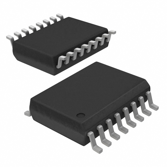
- Part No.:
- DS1110S-500/T&R
- Manufacturer:
- Analog Devices Inc./Maxim Integrated
- Category:
- Delay Lines
- Package:
- 16-SOIC (0.295", 7.50mm Width)
- Datasheet:
-
 DS1110S-500/T&R.pdf
- Description:
- IC DELAY LINE 10TAP 500NS 16SOIC
- Quantity:
- Payment:

- Shipping:

Inventory:1,341
Please send an inquiry. Send us your inquiry, and we will respond immediately.
Product details
Overview
DS1110S-500/T&R from Maxim Integrated is a 10-tap silicon delay line IC delivering precisely spaced 50ns increments across 10 outputs, with total delay of 500ns at 5V and +25°C, ±5% or ±2ns tolerance, TTL/CMOS-compatible, and designed for leading- and trailing-edge timing alignment in high-speed digital synchronization circuits.
For engineers reviewing the DS1110S-500/T&R datasheet, DS1110S-500/T&R pinout, DS1110S-500/T&R application, or DS1110S-500/T&R equivalent, this page provides verified package mapping (16-pin SO), tap-specific delay accuracy, temperature/voltage stability data, load-driving capability (10 × 74LS), and confirmed drop-in replacement status versus DS1010.
Technical Context
The DS1110S-500/T&R implements an all-silicon, low-power CMOS delay architecture with fixed, monotonic tap spacing-each tap advances delay by exactly 50ns, and all taps track unidirectionally with temperature or supply voltage changes. It operates over -40°C to +85°C with 4.75V–5.25V supply range.
Delay measurement is referenced to 1.5V crossing points on input and output edges (tPLH/tPHL), supporting both rising- and falling-edge precision. Input pulse width must be ≥10% of Tap 10 delay (≥50ns), and minimum period is 2×pulse width or 20ns-whichever is greater.
Key Specifications
| Parameter | Value and Actual Design Meaning |
|---|---|
| Total delay (Tap 10) | 500ns nominal at +25°C, 5.0V - defines maximum system timing offset for signal alignment |
| Delay per tap | 50ns fixed increment - enables precise sub-cycle phase stepping in clock/data recovery |
| Delay tolerance | ±5% or ±2ns (whichever greater) at +25°C, 5V - sets worst-case skew budget across all 10 outputs |
| Operating temperature | -40°C to +85°C - supports industrial-grade deployment without derating |
| Supply voltage | 4.75V to 5.25V - compatible with standard 5V logic rails and tolerates typical board-level ripple |
| Output drive strength | 12mA sink / -1mA source at VOL=0.5V / VOH=2.3V - drives up to ten 74LS loads per tap |
| Input capacitance | 5–10pF typical - minimizes loading on upstream drivers and preserves signal integrity |
Pinout & Package
DS1110S-500/T&R is packaged in a 16-pin SO (300-mil) surface-mount package with exposed pad not present; pin 1 is marked via notch or dot, and pin 16 is VCC. The package is vapor-phase, IR, and wave solderable per IPC/JEDEC J-STD-020A.
| Pin | Circuit Role | Design Meaning |
|---|---|---|
| 1 | VCC | 5.0V power supply input - requires local 0.1µF ceramic decoupling to GND |
| 2 | N.C. | No internal connection - must remain unconnected; no pull-up/down required |
| 3 | N.C. | No internal connection - must remain unconnected; no pull-up/down required |
| 4 | TAP1 | First delayed output - delivers 50ns delay; same edge polarity as input |
| 5 | TAP2 | Second delayed output - delivers 100ns delay; monotonic tracking with all other taps |
| 6 | TAP3 | Third delayed output - delivers 150ns delay; validated for 10 × 74LS fanout |
| 7 | TAP4 | Fourth delayed output - delivers 200ns delay; matches rising/falling edge accuracy |
| 8 | TAP5 | Fifth delayed output - delivers 250ns delay; stable over full -40°C to +85°C range |
| 9 | TAP6 | Sixth delayed output - delivers 300ns delay; unaffected by adjacent signal switching |
| 10 | TAP7 | Seventh delayed output - delivers 350ns delay; maintains ±5% tolerance across voltage |
| 11 | TAP8 | Eighth delayed output - delivers 400ns delay; verified in 500kHz–40MHz test conditions |
| 12 | TAP9 | Ninth delayed output - delivers 450ns delay; identical rise/fall delay matching |
| 13 | TAP10 | Tenth delayed output - delivers 500ns delay; primary reference point for timing calibration |
| 14 | GND | Ground reference - must connect to low-impedance system ground plane |
| 15 | N.C. | No internal connection - must remain unconnected; no pull-up/down required |
| 16 | IN | Single-ended logic input - accepts TTL/CMOS levels; 5–10pF input capacitance |
Key Features
| Feature | Design Value |
|---|---|
| 10-tap equal-spacing architecture | Guarantees deterministic 50ns step resolution across full 500ns range-enables predictable phase-shift synthesis |
| Leading- and trailing-edge matched delay | Ensures zero duty-cycle distortion across all taps-critical for clock forwarding and data eye alignment |
| Drop-in replacement for DS1010 | Same pinout, voltage, and timing behavior-allows legacy design upgrade without PCB revision |
| 10 × 74LS load drive per tap | Eliminates need for external buffer stages in moderate-fanout applications like ATE trigger distribution |
| Industrial temperature operation (-40°C to +85°C) | Validated performance across full range-no derating needed for embedded medical or comms equipment |
Applications
| Communications Equipment | Automated Test Equipment |
|---|---|
|
Use Scenario: Aligning transmit/receive data paths in serial backplane interfaces to compensate for trace-length mismatch. IC Role / Device Role / Timing Role: Precision tap-based delay element synchronizing parallel DDR strobes with data lanes. Use Value: Enables 500ns max skew correction with 50ns granularity-meeting JEDEC setup/hold windows without FPGA logic overhead. |
Use Scenario: Generating calibrated trigger delays for multi-channel oscilloscope or logic analyzer capture windows. IC Role / Device Role / Timing Role: Fixed-delay reference generator distributing time-shifted enable signals to channel front-ends. Use Value: Provides monotonic, temperature-stable delays-eliminating software-calibration drift in production test fixtures. |
| Medical Imaging Systems | PC Peripheral Devices |
|
Use Scenario: Synchronizing ultrasound transducer firing pulses across phased-array elements to steer acoustic beams. IC Role / Device Role / Timing Role: Deterministic delay node in analog beamforming control path. Use Value: Delivers ±2ns absolute delay accuracy at +25°C-supporting sub-micron spatial resolution in real-time imaging. |
Use Scenario: Compensating propagation delay between USB controller and hub PHY to meet USB 2.0 timing budgets. IC Role / Device Role / Timing Role: Interposer delay block adjusting data-valid-to-strobe alignment. Use Value: Achieves 50ns fine-tuning without requiring layout re-spin-accelerating peripheral compliance validation. |
Equivalent & Alternatives
The following parts are listed as comparable options for similar fixed-tap delay line applications.
| Alternative Part | Technical Difference | Application Difference | Selection Advice |
|---|---|---|---|
| DS1110E-500 | 14-pin TSSOP package; identical electrical specs, same 500ns delay and ±5%/±2ns tolerance | Higher board density; requires different footprint and reflow profile vs. SO | Select DS1110E-500 when space-constrained layouts or finer-pitch assembly processes are used |
| MAX9600 | 8-tap, 125ns max delay, ±3% accuracy, 3.3V-only supply; no 500ns option or 10-tap configuration | Limited to lower-speed applications; incompatible with 5V systems or >125ns requirements | Consider MAX9600 only for 3.3V designs needing <125ns delay and fewer taps |
Compared with DS1110E-500, DS1110S-500/T&R offers identical timing performance in a larger, more robust 16-pin SO package suited for manual prototyping and thermal cycling reliability; compared with MAX9600, DS1110S-500/T&R provides 4× longer delay range, 25% more taps, and 5V compatibility-making it the sole fit for industrial 500ns alignment tasks.
Availability
DS1110S-500/T&R is available at Aetrix Electronics and suitable for communications infrastructure, automated test equipment, and medical imaging systems requiring stable component supply, long-term lifecycle support, and guaranteed traceable sourcing.
Supply support for DS1110S-500/T&R includes scheduled delivery planning, volume procurement assistance, BOM continuity management, traceable sourcing, and lifecycle availability coordination for OEM customers, industrial embedded developers, connected-device designers, and electronics production programs.
Manufacturer
Maxim Integrated (now part of Analog Devices) is a U.S.-based semiconductor company specializing in precision analog, mixed-signal, and high-reliability timing solutions for industrial, medical, and communications markets.
The DS1110 series belongs to Maxim's fixed-tap silicon delay line product line, engineered specifically for deterministic, edge-aligned digital timing correction in systems where programmable delay ICs introduce jitter or complexity.
FAQ
What is the exact delay value at Tap 10 for DS1110S-500/T&R under nominal conditions?
The DS1110S-500/T&R delivers a nominal 500ns delay at Tap 10 when operated at +25°C and VCC = 5.0V. This value is specified in Table 1 of the datasheet and confirmed across all production lots. The DS1110S-500/T&R maintains this delay with ±5% or ±2ns tolerance-whichever is greater-under those conditions, and its monotonic tracking ensures all intermediate taps scale proportionally.
Does DS1110S-500/T&R support both rising- and falling-edge delay matching?
Yes, DS1110S-500/T&R is explicitly designed for equal precision on both edges: tPLH (rising) and tPHL (falling) delays are matched within specification across all 10 taps. The datasheet confirms this in the Features section ("Leading- and Trailing-Edge Accuracy") and AC Electrical Characteristics table, where both parameters share identical min/typ/max values under the same test conditions.
Can DS1110S-500/T&R drive standard TTL loads directly?
Yes, DS1110S-500/T&R can drive up to ten 74LS-type loads per tap without external buffering. Its IOL = 12mA (min) and IOH = -1mA (min) at VCC = 4.75V ensure sufficient current delivery for TTL-compatible thresholds. This capability is stated in the General Description and verified in the DC Electrical Characteristics table-making DS1110S-500/T&R suitable for direct interfacing in legacy logic systems.
Is DS1110S-500/T&R pin-compatible with the older DS1010 delay line?
Yes, DS1110S-500/T&R is documented as an improved, drop-in replacement for DS1010 in the Features and Detailed Description sections. Both share identical 16-pin SO pinout, supply voltage, logic thresholds, and functional behavior-requiring no PCB changes. The DS1110S-500/T&R improves upon DS1010 with tighter delay tolerance (±5% vs. older ±10%) and enhanced edge-matching performance.
What is the maximum operating frequency supported by DS1110S-500/T&R?
DS1110S-500/T&R does not specify a maximum clock frequency but defines minimum input period and pulse width constraints: period ≥ 2×tWI or 20ns (whichever greater), and tWI ≥ 10% of Tap 10 delay (i.e., ≥50ns). Thus, the practical upper limit is ~10MHz for reliable timing fidelity. This is derived from the AC Electrical Characteristics table and Figure 2 timing diagram-not from a rated "frequency" spec.
DS1110S-500/T&R Specifications
- Product attributes
- Attribute value
- Manufacturer:
- Analog Devices Inc./Maxim Integrated
- Series:
- -
- Package/Case:
- 16-SOIC (0.295", 7.50mm Width)
- Packaging:
- Tape & Reel (TR)
- Product Status:
- Obsolete
- Number of Taps/Steps:
- 10
- Function:
- Nonprogrammable
- Delay to 1st Tap:
- 50ns
- Tap Increment:
- 50 ns
- Available Total Delays:
- 500ns
- Number of Independent Delays:
- 1
- Voltage - Supply:
- 4.75V ~ 5.25V
- Operating Temperature:
- -40°C ~ 85°C
- Grade:
- -
- Qualification:
- -
- Mounting Type:
- Surface Mount
- Supplier Device Package:
- 16-SOIC
DS1110S-500/T&R FAQ
1.How can I place an order for DS1110S-500/T&R through Aetrix?
Please submit a Request for Quotation (RFQ) for DS1110S-500/T&R on Aetrix. Our sales agent will provide a competitive quotation and guide you through the order confirmation once you accept the terms.
2.Are the price and stock information for DS1110S-500/T&R reliable?
The price and inventory of DS1110S-500/T&R are updated periodically and may fluctuate due to market conditions. Stock and pricing data are typically refreshed every 24 hours. Quotation validity for DS1110S-500/T&R is usually 5 days.
3.What payment methods are accepted for DS1110S-500/T&R?
We accept Wire Transfer, PayPal, Credit Card, Western Union, MoneyGram, and Escrow for DS1110S-500/T&R transactions.
Note: Certain payment methods may incur a processing fee.
4.How is shipping managed for DS1110S-500/T&R?
DS1110S-500/T&R orders can be shipped via leading logistics carriers, including DHL, UPS, FedEx, TNT, or Registered Mail.
Once your DS1110S-500/T&R order is processed, you will receive an email with the shipment details and tracking number.
Note: Tracking information may take up to 24 hours to appear. Express delivery typically takes 3–5 business days.
5.How can I obtain technical support or documentation for DS1110S-500/T&R?
For technical support, including DS1110S-500/T&R datasheets, pinout diagrams, or application guidance, please contact our engineering support team. They can provide detailed documentation and assistance for your DS1110S-500/T&R requirements.
6.How does Aetrix verify that DS1110S-500/T&R is sourced from the original manufacturer or authorized distributors?
All DS1110S-500/T&R products on Aetrix are procured from qualified distributors and authorized channels. Our dedicated quality assurance team conducts strict verification, including traceability checks and, if necessary, third-party testing. This ensures that DS1110S-500/T&R meets industry standards.
7.What is the process for return or replacement of DS1110S-500/T&R?
All DS1110S-500/T&R units undergo pre-shipment inspection (PSI). If there is an issue with DS1110S-500/T&R, returns or replacements are accepted under the following conditions:
1.Quantity discrepancies, incorrect items, or visible external defects (such as breakage or corrosion), acknowledged by Aetrix.
2.The issue is reported within 90 days of delivery.
3.The DS1110S-500/T&R part is unused and in its original packaging.
Return procedure for DS1110S-500/T&R:
1.Submit a request within 90 days.
2.Obtain a Return Material Authorization (RMA) from Aetrix.
DS1110S-500/T&R Tags
-
LTC6994CS6-1#TRMPBF
Analog Devices Inc.
-
LTC6994CDCB-1#TRMPBF
Analog Devices Inc.
-
LTC6994IS6-1#TRMPBF
Analog Devices Inc.
-
LTC6994IS6-1#TRPBF
Analog Devices Inc.
-
LTC6994IDCB-1#TRMPBF
Analog Devices Inc.
-
LTC6994IS6-2#TRMPBF
Analog Devices Inc.
-
LTC6994HS6-1#TRPBF
Analog Devices Inc.
-
LTC6994HS6-1#TRMPBF
Analog Devices Inc.
-
LTC6994HS6-2#TRMPBF
Analog Devices Inc.
-
LTC6994HDCB-2#TRMPBF
Analog Devices Inc.
-
LTC6994HDCB-1#TRMPBF
Analog Devices Inc.
-
DS1124U-25+T
Analog Devices Inc./Maxim Integrated
Tech Hub

A practical engineering guide to 3.3V and 5V logic compatibility, input thresholds, resistor dividers, translator ICs, MOSFET level shifting, I2C pull-ups, timing limits and power-sequencing risks.

The 74HC595 uses push-pull logic outputs, while the TPIC6B595 uses 50 V open-drain DMOS sinks for higher-power loads. This guide compares timing, current limits, 3.3 V interfacing, load wiring, thermal…

The 74HC595 converts serial data into eight stable parallel outputs. This guide covers pin functions, shift and storage timing, OE and MR behavior, drive-current limits, cascading, voltage compatibilit…

A technical comparison of level-sensitive latches and edge-triggered flip-flops, covering timing windows, setup and hold limits, master–slave operation, time borrowing, race-through, HDL inference and…

A D latch stores one bit while Enable controls when data can pass. This reference covers gate-level operation, truth tables, transparency, setup and hold timing, LE versus OE, common ICs and practical …

An SR latch stores one bit through cross-coupled feedback. This engineering reference covers NOR and NAND implementations, truth tables, forbidden-state recovery, gated operation, switch debouncing, fa…

Latch circuits retain one bit through feedback. This technical reference covers SR and D latches, truth tables, transparency, timing limits, latch-versus-flip-flop behavior, applications and common log…

An engineering guide to LED driver operation, constant-current and constant-voltage outputs, linear and switching topologies, dimming, IC selection, calculations, replacement compatibility, and fault c…

Operational amplifier guide covering op amp basics, feedback, ideal vs real op amps, common configurations, buffer circuits, offset, bias current, gain-bandwidth, slew rate, rail-to-rail limits and sel…

Jumper cables guide covering safe connection order, red and black clamp placement, final ground connection, cable gauge, length, clamp quality, copper vs CCA cables, jump starter comparison and battery…


