
 My Inquiry
 My Account


Analog Devices Inc./Maxim Integrated DS1254YB2-100
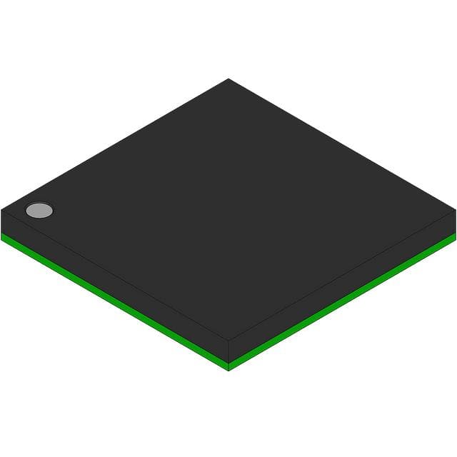
- Part No.:
- DS1254YB2-100
- Manufacturer:
- Analog Devices Inc./Maxim Integrated
- Category:
- Memory
- Package:
- 168-BBGA
- Datasheet:
-
 DS1254YB2-100.pdf
- Description:
- 2M X 8 NV SRAM, PHANTOM CLOCK
- Quantity:
- Payment:

- Shipping:

Inventory:2,333
Please send an inquiry. Send us your inquiry, and we will respond immediately.
Product details
Overview
DS1254YB2-100 from Maxim Integrated is a fully nonvolatile 2M × 8 static RAM with integrated real-time clock (RTC), +5V operation, 100ns read cycle time, and surface-mountable 40mm BGA package. It combines memory and timekeeping in a single module for telecom switches, RAID systems, and routers where data retention and accurate timestamping are critical during power loss.
For engineers reviewing the DS1254YB2-100 datasheet, DS1254YB2-100 pinout, DS1254YB2-100 application, or DS1254YB2-100 equivalent, key selection considerations include VCC = 5.0V ±10% operation, phantom clock pattern recognition protocol, battery-backed RTC register access via DQ0, BW open-drain battery warning output, and DS3800 battery cap interface requirements.
Technical Context
The DS1254YB2-100 integrates SRAM and RTC on a single die with a self-contained lithium energy source and dedicated circuitry to monitor VCC for power-fail conditions. When VCC drops below VPF (4.25V min), it automatically switches to battery power and disables memory access while preserving clock registers and stored data.
Timekeeping is implemented via a "phantom clock" accessed through a 64-bit serial pattern recognition sequence (C5, 3A, A3, 5C repeated) executed on DQ0 using CE/OE/WE control. The RTC maintains hundredths-of-seconds to years with auto leap-year compensation and supports both 12-hour (AM/PM) and 24-hour modes.
Key Specifications
| Parameter | Value and Actual Design Meaning |
|---|---|
| Memory Organization | 2M words × 8 bits (16MB total); enables direct byte-accessible storage without external refresh logic. |
| Supply Voltage | +5.0V ±10%; compatible with legacy 5V system rails and eliminates need for level-shifting in mixed-voltage designs. |
| Read Cycle Time | 100ns; supports high-speed CPU or FPGA interface timing without wait states in 5V systems. |
| Data Retention | ≥10 years with oscillator enabled; guaranteed operation from attached DS3800 battery cap under specified temperature and load conditions. |
| RTC Accuracy | Auto leap-year compensation up to year 2100; eliminates firmware date-handling overhead in embedded time-critical applications. |
| Battery Warning | BW open-drain output asserts when DS3800 voltage falls below ~2.6V; provides system-level alert for battery replacement planning. |
| Power-Fail Threshold | VPF = 4.25V to 4.50V; triggers seamless switchover to battery before SRAM write protection activates. |
Pinout & Package
DS1254YB2-100 uses a 40mm BGA package with 168 balls arranged on a 50-mil grid; corner balls omitted to accommodate mechanical and electrical interface for DS3800 battery cap attachment. Package dimensions: 40.13mm × 40.13mm × 6.10mm (max height with cap).
| Pin/Terminal | Circuit Role | Design Meaning |
|---|---|---|
| VCC | Main power supply input | Accepts +5.0V ±10%; powers SRAM core, RTC, and control logic; monitored continuously for power-fail detection. |
| GND | Ground reference | Multiple dedicated ground balls provide low-impedance return paths for memory I/O and RTC circuitry. |
| A0–A20 | Address inputs | 21-bit address bus selects one of 2M locations; A19/A20 have reduced capacitance (5–10pF) for timing margin. |
| DQ0–DQ7 | Data I/O lines | 8-bit bidirectional bus; DQ0 carries serial phantom clock data during pattern recognition and register access. |
| CE, OE, WE | Memory control signals | Chip enable, output enable, write enable; jointly manage SRAM access and initiate phantom clock protocol sequencing. |
| BW | Battery warning output | Open-drain signal asserted low when DS3800 battery voltage drops below ~2.6V; requires external pull-up. |
| BAT | Battery cap interface | Direct connection point for DS3800 battery capacitor; enables automatic battery monitoring and switchover. |
Key Features
| Feature | Design Value |
|---|---|
| Phantom clock protocol | 64-bit pattern recognition (C5, 3A, A3, 5C ×2) prevents accidental RTC access; false-trigger probability <1 in 10¹⁹. |
| Automatic data protection | Hardware-enforced write blocking during power fail; no firmware intervention required to preserve integrity. |
| Unlimited write-cycle endurance | SRAM cells retain full specification performance across infinite write cycles-no wear-out mechanism. |
| Dedicated battery monitoring | 24-hour periodic DS3800 voltage test with tBPU = 1s BW assertion delay; enables predictive maintenance. |
| Transparent RTC operation | Watch function runs independently of memory access; no timing penalty or arbitration needed during normal reads/writes. |
Applications
| Telecom Switches | RAID Systems |
|---|---|
Use Scenario: Maintaining call routing tables and session state during AC power interruption in carrier-grade switching hardware. IC Role / Device Role / Timing Role: Nonvolatile SRAM stores active configuration; phantom clock timestamps fault logs and session start times with millisecond resolution. Use Value: Enables zero-downtime failover by preserving volatile state and precise event timing without external backup controllers. | Use Scenario: Caching write operations and storing parity metadata in enterprise storage arrays with dual-controller redundancy. IC Role / Device Role / Timing Role: Acts as battery-backed write cache; RTC provides synchronized timestamps across mirrored controllers for consistent log replay. Use Value: Eliminates need for supercapacitor-based backup modules while ensuring atomicity and temporal ordering of cached writes. |
| Routers | Industrial Data Loggers |
Use Scenario: Storing routing table updates, ACL rules, and SNMP counters during brownouts in edge networking equipment. IC Role / Device Role / Timing Role: NV SRAM retains dynamic forwarding information; phantom clock tracks uptime, reboot events, and policy activation times. Use Value: Provides deterministic recovery with full state restoration and auditable time-stamped change history post-power restoration. | Use Scenario: Recording sensor readings and alarm events in remote environmental monitoring units powered by intermittent solar/battery sources. IC Role / Device Role / Timing Role: Serves as persistent data buffer with integrated time stamping; BW output triggers field-replaceable battery alerts. Use Value: Reduces BOM count by merging memory and RTC functions, while enabling long-term unattended operation with calendar-aware logging. |
Equivalent & Alternatives
The following parts are listed as comparable options for similar nonvolatile SRAM with RTC applications.
| Alternative Part | Technical Difference | Application Difference | Selection Advice |
|---|---|---|---|
| DS1254WB2-150 | +3.3V operation, 150ns read cycle, same 40mm BGA package and phantom clock architecture. | Targeted at low-power 3.3V systems; incompatible with 5V-only buses without level translation. | Select when system rail is 3.3V and timing budget allows 150ns access; identical pinout and protocol but different voltage domain. |
| STK15C88 | 2M × 8 NV SRAM with RTC, +5V operation, but uses parallel RTC register interface (no phantom clock pattern recognition). | Requires dedicated RTC control pins (SCLK, SDATA); lacks integrated battery monitoring and BW output. | Choose when simpler RTC register mapping is preferred over serial pattern protocol; verify DS3800 compatibility and absence of automatic battery test. |
Compared with DS1254WB2-150, DS1254YB2-100 delivers faster 100ns access at 5V but consumes more active current; versus STK15C88, it offers superior system integration via phantom clock and built-in battery health monitoring, reducing firmware complexity and external component count.
Availability
DS1254YB2-100 is available at Aetrix Electronics and suitable for telecom switches, RAID systems, and industrial routers requiring stable component supply, long-life data retention, and integrated timekeeping without external RTC or backup controllers.
Supply support for DS1254YB2-100 includes scheduled delivery planning, volume procurement assistance, BOM continuity management, traceable sourcing, and lifecycle availability coordination for OEM customers, industrial embedded developers, connected-device designers, and electronics production programs.
Manufacturer
Maxim Integrated (now part of Analog Devices) designs precision analog, mixed-signal, and digital ICs for industrial, communications, computing, and consumer applications.
The DS1254YB2-100 belongs to Maxim's nonvolatile memory product line, engineered to eliminate external battery backup circuitry and simplify time-critical data logging in infrastructure equipment.
FAQ
What is the operating voltage range for DS1254YB2-100?
The DS1254YB2-100 operates at +5.0V ±10%, with absolute maximum ratings from -0.3V to +6.0V on any pin relative to ground. Its VPF (write protection voltage) is specified from 4.25V to 4.50V, ensuring reliable power-fail detection and battery switchover. This 5V compatibility makes DS1254YB2-100 suitable for legacy industrial and telecom systems without level-shifting circuitry.
How does the phantom clock in DS1254YB2-100 differ from standard RTC interfaces?
The phantom clock in DS1254YB2-100 uses a 64-bit serial pattern recognition protocol (C5, 3A, A3, 5C repeated) executed on DQ0 using CE/OE/WE signals-no dedicated RTC pins required. Unlike parallel-register RTCs, this method prevents accidental access with a false-trigger probability under 1 in 10¹⁹. Once recognized, the next 64 cycles read/write eight 8-bit registers containing hundredths-of-seconds to year data, all managed within DS1254YB2-100's unified memory map.
What battery is required for DS1254YB2-100 data retention?
The DS1254YB2-100 requires the DS3800 lithium battery capacitor for data retention and RTC operation during power loss. It monitors the DS3800 voltage daily and asserts the open-drain BW output when voltage falls below ~2.6V. The DS3800 is a one-time-use, mechanically keyed component designed specifically for DS1254YB2-100; substitution with generic capacitors voids the 10-year retention guarantee and disables battery health reporting.
Does DS1254YB2-100 support both 12-hour and 24-hour time formats?
Yes, DS1254YB2-100 supports both formats via bit 7 of the hours register: logic high selects 12-hour mode with AM/PM indication (bit 5), while logic low selects 24-hour mode (0–23 hours). The RTC automatically adjusts day-of-month for months with fewer than 31 days and includes leap-year compensation valid through year 2100-no host processor intervention is needed to maintain calendar accuracy in DS1254YB2-100.
What is the significance of the 'B2' suffix in DS1254YB2-100?
The 'B2' suffix in DS1254YB2-100 denotes the second revision of the 40mm BGA package variant rated for +5V operation and 100ns timing. It reflects mechanical and electrical refinements including optimized ball layout for DS3800 cap attachment, improved thermal dissipation, and updated AC timing parameters (e.g., tAW minimum increased to 10ns per revision history). This distinguishes it from earlier DS1254YB-100 units and ensures compatibility with current production land patterns and assembly processes.
DS1254YB2-100 Specifications
- Product attributes
- Attribute value
- Manufacturer:
- Analog Devices Inc./Maxim Integrated
- Series:
- -
- Package/Case:
- 168-BBGA
- Packaging:
- Bulk
- Product Status:
- Active
- Programmable:
- Not Verified
- Memory Type:
- Non-Volatile
- Memory Format:
- NVSRAM
- Technology:
- NVSRAM (Non-Volatile SRAM)
- Memory Size:
- 16Mbit
- Memory Organization:
- 2M x 8
- Memory Interface:
- Parallel
- Clock Frequency:
- -
- Write Cycle Time - Word, Page:
- 100ns
- Access Time:
- 100 ns
- Voltage - Supply:
- 3V ~ 3.7V
- Operating Temperature:
- 0°C ~ 70°C (TA)
- Grade:
- -
- Qualification:
- -
- Mounting Type:
- Surface Mount
- Supplier Device Package:
- 168-BGA (16x16)
DS1254YB2-100 FAQ
1.How can I place an order for DS1254YB2-100 through Aetrix?
Please submit a Request for Quotation (RFQ) for DS1254YB2-100 on Aetrix. Our sales agent will provide a competitive quotation and guide you through the order confirmation once you accept the terms.
2.Are the price and stock information for DS1254YB2-100 reliable?
The price and inventory of DS1254YB2-100 are updated periodically and may fluctuate due to market conditions. Stock and pricing data are typically refreshed every 24 hours. Quotation validity for DS1254YB2-100 is usually 5 days.
3.What payment methods are accepted for DS1254YB2-100?
We accept Wire Transfer, PayPal, Credit Card, Western Union, MoneyGram, and Escrow for DS1254YB2-100 transactions.
Note: Certain payment methods may incur a processing fee.
4.How is shipping managed for DS1254YB2-100?
DS1254YB2-100 orders can be shipped via leading logistics carriers, including DHL, UPS, FedEx, TNT, or Registered Mail.
Once your DS1254YB2-100 order is processed, you will receive an email with the shipment details and tracking number.
Note: Tracking information may take up to 24 hours to appear. Express delivery typically takes 3–5 business days.
5.How can I obtain technical support or documentation for DS1254YB2-100?
For technical support, including DS1254YB2-100 datasheets, pinout diagrams, or application guidance, please contact our engineering support team. They can provide detailed documentation and assistance for your DS1254YB2-100 requirements.
6.How does Aetrix verify that DS1254YB2-100 is sourced from the original manufacturer or authorized distributors?
All DS1254YB2-100 products on Aetrix are procured from qualified distributors and authorized channels. Our dedicated quality assurance team conducts strict verification, including traceability checks and, if necessary, third-party testing. This ensures that DS1254YB2-100 meets industry standards.
7.What is the process for return or replacement of DS1254YB2-100?
All DS1254YB2-100 units undergo pre-shipment inspection (PSI). If there is an issue with DS1254YB2-100, returns or replacements are accepted under the following conditions:
1.Quantity discrepancies, incorrect items, or visible external defects (such as breakage or corrosion), acknowledged by Aetrix.
2.The issue is reported within 90 days of delivery.
3.The DS1254YB2-100 part is unused and in its original packaging.
Return procedure for DS1254YB2-100:
1.Submit a request within 90 days.
2.Obtain a Return Material Authorization (RMA) from Aetrix.
DS1254YB2-100 Tags

-
M24C02-WMN6TP
STMicroelectronics

-
AT24C02C-XHM-T
Microchip Technology

-
AT21CS01-STUM10-T
Microchip Technology

-
AT24C02C-SSHM-T
Microchip Technology

-
24LC01BT-I/OT
Microchip Technology

-
M24C02-FMC6TG
STMicroelectronics
-
AT24CS02-SSHM-T
Microchip Technology

-
93LC46BT-I/OT
Microchip Technology
-
AT24C04C-SSHM-T
Microchip Technology

-
24LC01BT-I/SN
Microchip Technology
-
24AA02UIDT-I/OT
Microchip Technology

-
AT24C08C-STUM-T
Microchip Technology
Tech Hub
Schmitt triggers use separate rising and falling thresholds to stabilize slow or noisy signals. This guide covers hysteresis, 74HC14 and 74HCT14 selection, comparator calculations, RC oscillators and p…

Counterfeit components can hide behind convincing markings and passing basic function tests. This engineering reference covers source traceability, external inspection, X-ray, XRF, electrical testing, …

A practical engineering and sourcing framework covering lifecycle verification, lifetime-buy calculations, replacement qualification, supplier checks and counterfeit-risk controls.

TTL and CMOS logic families differ in thresholds, loading, output drive, power and timing. This engineering guide compares 74HC and 74HCT, calculates noise margins and checks 3.3 V/5 V compatibility.

A practical engineering guide to 3.3V and 5V logic compatibility, input thresholds, resistor dividers, translator ICs, MOSFET level shifting, I2C pull-ups, timing limits and power-sequencing risks.

The 74HC595 uses push-pull logic outputs, while the TPIC6B595 uses 50 V open-drain DMOS sinks for higher-power loads. This guide compares timing, current limits, 3.3 V interfacing, load wiring, thermal…

The 74HC595 converts serial data into eight stable parallel outputs. This guide covers pin functions, shift and storage timing, OE and MR behavior, drive-current limits, cascading, voltage compatibilit…

A technical comparison of level-sensitive latches and edge-triggered flip-flops, covering timing windows, setup and hold limits, master–slave operation, time borrowing, race-through, HDL inference and…

A D latch stores one bit while Enable controls when data can pass. This reference covers gate-level operation, truth tables, transparency, setup and hold timing, LE versus OE, common ICs and practical …

An SR latch stores one bit through cross-coupled feedback. This engineering reference covers NOR and NAND implementations, truth tables, forbidden-state recovery, gated operation, switch debouncing, fa…


