
 My Inquiry
 My Account


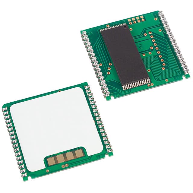
Analog Devices Inc./Maxim Integrated DS1350ABP-70+
- Part No.:
- DS1350ABP-70+
- Manufacturer:
- Analog Devices Inc./Maxim Integrated
- Category:
- Memory
- Package:
- 34-PowerCap™ Module
- Datasheet:
-
 DS1350ABP-70+.pdf
- Description:
- IC NVSRAM 4MBIT PAR 34PWRCAP
- Quantity:
- Payment:

- Shipping:

Inventory:2,174
Please send an inquiry. Send us your inquiry, and we will respond immediately.
Product details
Overview
DS1350ABP-70+ from Maxim Integrated is a 4,194,304-bit (524,288 × 8) nonvolatile SRAM with integrated lithium backup, PowerCap Module (PCM) packaging, 70ns access time, ±5% VCC tolerance (4.75V–5.25V), and industrial-grade battery monitoring. It serves as a drop-in replacement for 512k × 8 SRAM/EEPROM/Flash in mission-critical data logging systems requiring guaranteed retention during power loss.
For engineers reviewing the DS1350ABP-70+ datasheet, DS1350ABP-70+ pinout, DS1350ABP-70+ application, or DS1350ABP-70+ equivalent, key selection criteria include its 70ns read/write timing, open-drain RST/BW outputs with 10mA sink capability, 50µA typical standby current, 10-year data retention claim, and PCM-specific surface-mount + snap-on PowerCap architecture requiring DS9034PC+.
Technical Context
The DS1350ABP-70+ implements autonomous power-fail detection at VTP = 4.50–4.75V, triggering unconditional write protection and high-impedance I/O within 1.5µs (tPD). Its internal circuitry switches to lithium backup below ~2.7V while holding RST active for 200ms during power-up to suppress transients.
It features dual-mode battery monitoring: daily 1-second load test via 1MΩ resistor, with BW assertion if voltage drops below 2.6V; BW remains latched until replacement or retest confirms >2.6V. All control signals (CE, WE, OE) and address/data lines operate under strict 70ns AC timing constraints with tCOE = 5ns and tODW = 25ns.
Key Specifications
| Parameter | Value and Actual Design Meaning |
|---|---|
| Memory Density | 4,194,304 bits (524,288 × 8) - supports byte-wide data bus without external multiplexing |
| Access Time | 70ns - enables direct interface with 14MHz microcontrollers without wait states |
| VCC Operating Range | 4.75V to 5.25V (±5%) - ensures compatibility with regulated 5V rails in industrial PLCs |
| Standby Current | 50µA typical - minimizes battery drain during extended backup-only operation |
| Data Retention | 10 years minimum without external power - verified by component-level aging and process controls |
| Write Endurance | Unlimited - no wear-out mechanism unlike EEPROM/Flash, enabling real-time logging |
| Temperature Range | 0°C to +70°C - commercial grade; IND variant available for -40°C to +85°C |
| PowerCap Interface | Requires DS9034PC+ or DS9034PCI+ - snap-on module provides field-replaceable lithium source |
Pinout & Package
DS1350ABP-70+ uses a 34-pin PowerCap Module (PCM) package - a surface-mountable hybrid assembly integrating SRAM die, control logic, and battery interface contacts. The PCM is designed for reflow soldering prior to PowerCap attachment; the DS9034PC+ snaps on post-assembly to complete the NV SRAM function.
| Pin/Terminal | Circuit Role | Design Meaning |
|---|---|---|
| A0–A18 | Address Inputs | 19-bit address bus supporting full 524,288-word addressing; TTL-compatible inputs |
| DQ0–DQ7 | Data I/O | Bi-directional 8-bit data bus; high-impedance when CE/OE inactive or during power fail |
| CE | Chip Enable | Active-low chip select; initiates read/write when low with WE/OE conditions met |
| WE | Write Enable | Active-low write strobe; falling edge (with CE) defines write start; open-drain compatible |
| OE | Output Enable | Active-low output control; disables drivers during writes to prevent bus contention |
| RST | Reset Output | Open-drain reset signal; asserted during VCC ramp-up (200ms) and power failure |
| BW | Battery Warning | Open-drain latched warning; active when battery voltage <2.6V after daily test |
| VCC | Power Supply | +5V supply input; monitored for out-of-tolerance condition triggering backup mode |
| GND | Ground | Reference return path for all digital and analog functions including battery sensing |
Key Features
| Feature | Design Value |
|---|---|
| Autonomous Power-Fail Response | Switches to lithium backup and enables write protection within 1.5µs of VCC decay past VTP |
| Daily Battery Health Check | Automatically applies 1MΩ load for 1 second every 24 hours; asserts BW if voltage <2.6V |
| Field-Replaceable PowerCap | DS9034PC+ snaps onto pre-soldered PCM; keyed design prevents misalignment |
| Lithium Freshness Preservation | Battery electrically disconnected until first VCC application - extends shelf life and retention window |
| Standardized NV SRAM Pinout | 34-pin PCM layout shared across Maxim's NV SRAM family - simplifies board reuse |
Applications
| Industrial Data Logger | Medical Device Memory Backup |
|---|---|
Use Scenario: Continuous acquisition of sensor readings in remote oil-field telemetry units with intermittent mains power. IC Role / Device Role / Timing Role: Nonvolatile SRAM storing last-known operational state and raw sensor buffers during grid outage. Use Value: 10-year retention and 70ns access enable immediate resumption of logging upon power restoration without firmware recovery overhead. | Use Scenario: ECG monitor retaining patient waveform history across battery swaps and AC power interruptions. IC Role / Device Role / Timing Role: Primary data buffer with guaranteed integrity during power transitions; RST synchronizes MCU reset with VCC stabilization. Use Value: Unlimited write cycles eliminate flash wear concerns; open-drain BW alerts clinical staff to replace PowerCap before battery depletion. |
| Avionics Black Box Recorder | Smart Grid Protection Relay |
Use Scenario: Crash-protected flight data recorder capturing critical parameters during rapid power collapse. IC Role / Device Role / Timing Role: High-speed memory capturing last 30 seconds of telemetry; triggered by RST assertion on VCC decay. Use Value: 1.5µs tPD ensures zero data loss between power fault detection and write protection activation. | Use Scenario: Fault-recording relay preserving trip-coil actuation timestamps and pre-fault voltage/current samples. IC Role / Device Role / Timing Role: Nonvolatile storage for event logs and configuration registers; BW flag enables predictive maintenance scheduling. Use Value: ±5% VCC tolerance accommodates wide-input DC-DC converters; 50µA standby extends backup runtime during extended brownouts. |
Equivalent & Alternatives
The following parts are listed as comparable options for similar nonvolatile SRAM applications.
| Alternative Part | Technical Difference | Application Difference | Selection Advice |
|---|---|---|---|
| DS1350YP-70+ | Wider VCC range (4.5V–5.5V, ±10%), lower VTP (4.25–4.5V); same 70ns timing and PCM package | Better suited for unregulated 5V supplies with higher ripple; less margin for brownout detection | Select DS1350YP-70+ when system VCC varies beyond ±5%; otherwise DS1350ABP-70+ offers tighter regulation tolerance |
| STK13C68-J15F | 4Mbit NV SRAM in SOIC-32; 150ns access; no integrated battery monitor or RST output | Lacks autonomous reset signaling and daily battery health check; requires external supervisor IC | Choose STK13C68-J15F only if board space prohibits PCM height or if legacy SOIC footprint must be retained |
Compared with DS1350YP-70+, DS1350ABP-70+ provides stricter VCC regulation compliance and earlier write-protection activation, while STK13C68-J15F sacrifices integrated supervision for standard packaging - making DS1350ABP-70+ optimal for new designs prioritizing reliability over footprint constraints.
Availability
DS1350ABP-70+ is available at Aetrix Electronics and suitable for industrial data loggers, medical device memory backup, avionics recorders, and smart grid relays requiring stable component supply with guaranteed 10-year data retention and field-replaceable backup power.
Supply support for DS1350ABP-70+ includes scheduled delivery planning, volume procurement assistance, BOM continuity management, traceable sourcing, and lifecycle availability coordination for OEM customers, industrial embedded developers, connected-device designers, and electronics production programs.
Manufacturer
Maxim Integrated (now part of Analog Devices) designs precision analog, mixed-signal, and power management ICs for industrial, medical, and communications applications.
The DS1350ABP-70+ belongs to Maxim's nonvolatile SRAM product line, engineered specifically for systems demanding zero-data-loss memory backup during unpredictable power failures - combining SRAM speed with autonomous battery management.
FAQ
What is the required companion component for DS1350ABP-70+ to function as a complete nonvolatile SRAM?
The DS1350ABP-70+ requires the DS9034PC+ or DS9034PCI+ PowerCap to be snapped onto its 34-pin PowerCap Module base. The PCM contains the SRAM and control logic but no battery; the PowerCap provides the lithium energy source and completes the nonvolatile functionality. Both components are ordered separately and shipped in distinct containers per Maxim's ordering specification.
How does DS1350ABP-70+ ensure data integrity during power failure?
DS1350ABP-70+ continuously monitors VCC and triggers write protection within 1.5µs (tPD) when voltage falls below 4.50–4.75V (VTP). It then places all inputs in "don't care" state and drives outputs to high-impedance. At ~2.7V, it seamlessly switches to lithium backup power to retain RAM contents - all without host intervention or external circuitry.
What is the purpose of the BW pin on DS1350ABP-70+ and how is it used?
The BW (Battery Warning) pin on DS1350ABP-70+ is an open-drain output that latches active when the internal lithium battery voltage drops below 2.6V during its daily 1-second test. Once asserted, BW remains active until the PowerCap is replaced or subsequent testing confirms voltage >2.6V. External pull-up is required, and BW can sink up to 10mA for direct LED or microcontroller interrupt use.
Can DS1350ABP-70+ operate without the PowerCap installed?
No - DS1350ABP-70+ cannot retain data without the DS9034PC+ or DS9034PCI+ PowerCap physically attached. The PCM base contains no battery; the PowerCap provides both the lithium cell and the electrical interface. While the SRAM may function temporarily on VCC alone, nonvolatility - including 10-year retention and autonomous backup - is only enabled with the correct PowerCap snapped into place.
What is the significance of the "-70" suffix in DS1350ABP-70+?
The "-70" suffix in DS1350ABP-70+ denotes a 70ns access time rating - specifying maximum tACC, tRC, and tWC values under valid operating conditions. This guarantees the device meets tight timing windows for interfacing with high-speed microcontrollers and FPGAs without added wait states, distinguishing it from slower variants like -100 or -120 versions in the same family.
DS1350ABP-70+ Specifications
- Product attributes
- Attribute value
- Manufacturer:
- Analog Devices Inc./Maxim Integrated
- Series:
- -
- Package/Case:
- 34-PowerCap™ Module
- Packaging:
- Bulk
- Product Status:
- Obsolete
- Programmable:
- Not Verified
- Memory Type:
- Non-Volatile
- Memory Format:
- NVSRAM
- Technology:
- NVSRAM (Non-Volatile SRAM)
- Memory Size:
- 4Mbit
- Memory Organization:
- 512K x 8
- Memory Interface:
- Parallel
- Clock Frequency:
- -
- Write Cycle Time - Word, Page:
- 70ns
- Access Time:
- 70 ns
- Voltage - Supply:
- 4.75V ~ 5.25V
- Operating Temperature:
- 0°C ~ 70°C (TA)
- Grade:
- -
- Qualification:
- -
- Mounting Type:
- Surface Mount
- Supplier Device Package:
- 34-PowerCap Module
DS1350ABP-70+ FAQ
1.How can I place an order for DS1350ABP-70+ through Aetrix?
Please submit a Request for Quotation (RFQ) for DS1350ABP-70+ on Aetrix. Our sales agent will provide a competitive quotation and guide you through the order confirmation once you accept the terms.
2.Are the price and stock information for DS1350ABP-70+ reliable?
The price and inventory of DS1350ABP-70+ are updated periodically and may fluctuate due to market conditions. Stock and pricing data are typically refreshed every 24 hours. Quotation validity for DS1350ABP-70+ is usually 5 days.
3.What payment methods are accepted for DS1350ABP-70+?
We accept Wire Transfer, PayPal, Credit Card, Western Union, MoneyGram, and Escrow for DS1350ABP-70+ transactions.
Note: Certain payment methods may incur a processing fee.
4.How is shipping managed for DS1350ABP-70+?
DS1350ABP-70+ orders can be shipped via leading logistics carriers, including DHL, UPS, FedEx, TNT, or Registered Mail.
Once your DS1350ABP-70+ order is processed, you will receive an email with the shipment details and tracking number.
Note: Tracking information may take up to 24 hours to appear. Express delivery typically takes 3–5 business days.
5.How can I obtain technical support or documentation for DS1350ABP-70+?
For technical support, including DS1350ABP-70+ datasheets, pinout diagrams, or application guidance, please contact our engineering support team. They can provide detailed documentation and assistance for your DS1350ABP-70+ requirements.
6.How does Aetrix verify that DS1350ABP-70+ is sourced from the original manufacturer or authorized distributors?
All DS1350ABP-70+ products on Aetrix are procured from qualified distributors and authorized channels. Our dedicated quality assurance team conducts strict verification, including traceability checks and, if necessary, third-party testing. This ensures that DS1350ABP-70+ meets industry standards.
7.What is the process for return or replacement of DS1350ABP-70+?
All DS1350ABP-70+ units undergo pre-shipment inspection (PSI). If there is an issue with DS1350ABP-70+, returns or replacements are accepted under the following conditions:
1.Quantity discrepancies, incorrect items, or visible external defects (such as breakage or corrosion), acknowledged by Aetrix.
2.The issue is reported within 90 days of delivery.
3.The DS1350ABP-70+ part is unused and in its original packaging.
Return procedure for DS1350ABP-70+:
1.Submit a request within 90 days.
2.Obtain a Return Material Authorization (RMA) from Aetrix.
DS1350ABP-70+ Tags

-
M24C02-WMN6TP
STMicroelectronics

-
AT24C02C-XHM-T
Microchip Technology

-
AT21CS01-STUM10-T
Microchip Technology

-
AT24C02C-SSHM-T
Microchip Technology

-
24LC01BT-I/OT
Microchip Technology

-
M24C02-FMC6TG
STMicroelectronics
-
AT24CS02-SSHM-T
Microchip Technology

-
93LC46BT-I/OT
Microchip Technology
-
AT24C04C-SSHM-T
Microchip Technology

-
24LC01BT-I/SN
Microchip Technology
-
24AA02UIDT-I/OT
Microchip Technology

-
AT24C08C-STUM-T
Microchip Technology
Tech Hub

A practical engineering and sourcing framework covering lifecycle verification, lifetime-buy calculations, replacement qualification, supplier checks and counterfeit-risk controls.

TTL and CMOS logic families differ in thresholds, loading, output drive, power and timing. This engineering guide compares 74HC and 74HCT, calculates noise margins and checks 3.3 V/5 V compatibility.

A practical engineering guide to 3.3V and 5V logic compatibility, input thresholds, resistor dividers, translator ICs, MOSFET level shifting, I2C pull-ups, timing limits and power-sequencing risks.

The 74HC595 uses push-pull logic outputs, while the TPIC6B595 uses 50 V open-drain DMOS sinks for higher-power loads. This guide compares timing, current limits, 3.3 V interfacing, load wiring, thermal…

The 74HC595 converts serial data into eight stable parallel outputs. This guide covers pin functions, shift and storage timing, OE and MR behavior, drive-current limits, cascading, voltage compatibilit…

A technical comparison of level-sensitive latches and edge-triggered flip-flops, covering timing windows, setup and hold limits, master–slave operation, time borrowing, race-through, HDL inference and…

A D latch stores one bit while Enable controls when data can pass. This reference covers gate-level operation, truth tables, transparency, setup and hold timing, LE versus OE, common ICs and practical …

An SR latch stores one bit through cross-coupled feedback. This engineering reference covers NOR and NAND implementations, truth tables, forbidden-state recovery, gated operation, switch debouncing, fa…

Latch circuits retain one bit through feedback. This technical reference covers SR and D latches, truth tables, transparency, timing limits, latch-versus-flip-flop behavior, applications and common log…

An engineering guide to LED driver operation, constant-current and constant-voltage outputs, linear and switching topologies, dimming, IC selection, calculations, replacement compatibility, and fault c…


