
 My Inquiry
 My Account


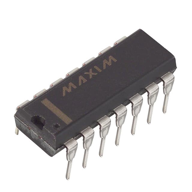
Analog Devices Inc./Maxim Integrated DS1868-10+
- Part No.:
- DS1868-10+
- Manufacturer:
- Analog Devices Inc./Maxim Integrated
- Category:
- Digital Potentiometers
- Package:
- 14-DIP (0.300", 7.62mm)
- Datasheet:
-
 DS1868-10+.pdf
- Description:
- IC DGTL POT 10KOHM 256TAP 14DIP
- Quantity:
- Payment:

- Shipping:

Inventory:1,188
Please send an inquiry. Send us your inquiry, and we will respond immediately.
Product details
Overview
DS1868-10+ from Analog Devices (formerly Dallas Semiconductor) is a dual-channel, 256-tap digital potentiometer with 10 kΩ end-to-end resistance per channel, operated via 3-wire serial interface (RST/CLK/DQ), supporting stacked and cascaded configurations for extended resistance range and multi-device control in analog signal conditioning circuits.
For engineers reviewing the DS1868-10+ datasheet, DS1868-10+ pinout, DS1868-10+ application, or DS1868-10+ equivalent, key selection considerations include its ±0.3 LSB relative linearity, ultra-low 400 µA supply current at 5 V, industrial -40°C to +85°C operation, and support for series stacking to achieve 20 kΩ total resistance with 512-step resolution.
Technical Context
The DS1868-10+ integrates two independent 256-position resistive ladders with temperature-compensated elements (±0.3 LSB relative linearity), each controlled by an 8-bit wiper value stored in a 17-bit I/O shift register that also includes a stack-select bit. Communication uses a synchronous 3-wire protocol requiring RST activation before CLK/DQ data transfer.
It supports two advanced topologies: stacked configuration (H0–L0 and H1–L1 connected in series, SOUT multiplexing W0/W1 based on stack bit) and daisy-chained cascade (COUT of one device drives DQ of next, enabling multi-unit control over single bus with 17×N-bit transactions).
Key Specifications
| Parameter | Value and Actual Design Meaning |
|---|---|
| Resistance Value | 10 kΩ per potentiometer; enables precise gain/attenuation scaling in 5 V analog front-ends without external scaling resistors. |
| Resolution | 256 positions per channel (8-bit); provides 0.39% step resolution for fine analog tuning in closed-loop systems. |
| Linearity | ±0.3 LSB relative linearity; ensures monotonic voltage division across full wiper travel, critical for sensor calibration and DAC replacement. |
| Supply Current | 400 µA typical at 5 V; allows battery-powered or low-power embedded systems to retain analog trim without significant quiescent load. |
| Operating Temp | -40°C to +85°C industrial grade; guarantees stable resistance ratio and wiper behavior across automotive and industrial ambient conditions. |
| Interface | 3-wire serial (RST/CLK/DQ); eliminates need for I²C or SPI peripherals-compatible with GPIO-driven microcontrollers using bit-banged timing. |
| Wiper Resistance | 400–1000 Ω; must be accounted for in high-impedance feedback paths (e.g., op-amp gain networks) to avoid gain error. |
Pinout & Package
DS1868-10+ is available in 20-pin TSSOP (173-mil), 16-pin SOIC (300-mil), and 14-pin DIP (300-mil) packages. Pin functions are identical across packages except for NC/DNC pin count variations; all GND pins must be connected.
| Pin/Terminal | Circuit Role | Design Meaning |
|---|---|---|
| L0, L1 | Low-end terminals of potentiometers | Reference nodes for resistor ladder; connect to circuit ground or bias reference to define lower voltage boundary. |
| H0, H1 | High-end terminals of potentiometers | Define upper voltage rail for each pot; must remain within VB−0.5 V to VCC+0.5 V limits. |
| W0, W1 | Wiper outputs | Provide variable voltage taps; output impedance varies 400–1000 Ω depending on position and voltage-requires high-Z loading. |
| SOUT | Stacked output multiplexer | Delivers W0 or W1 based on stack-select bit; used when potentiometers are series-connected for 20 kΩ total resistance. |
| RST | Serial port enable input | Active-high signal initiating communication; must transition low→high to start transaction and return low to latch new wiper values. |
| CLK | Serial clock input | Drives synchronous data sampling on rising edge; supports up to 10 MHz for fast reconfiguration (<1.7 µs per 17-bit write). |
| DQ | Serial bidirectional data | Carries 17-bit shift register contents (stack bit + W1 + W0); requires external pull-up for open-drain compatibility. |
| COUT | Cascade output | Propagates stack bit after 50 ns delay; enables daisy-chaining multiple DS1868-10+ units with single processor interface. |
| VCC / GND | Power supply | +5 V ±10% supply; all GND pins must be tied to common ground plane to ensure noise immunity and linearity stability. |
Key Features
| Feature | Design Value |
|---|---|
| Stacked configuration support | Enables series connection of both potentiometers to double total resistance (20 kΩ) while preserving 256-step resolution per segment and offering 512-step effective wiper control via SOUT. |
| Daisy-chain cascade capability | Allows up to N devices on one 3-wire bus using COUT→DQ interconnect; reduces MCU GPIO count and simplifies BOM for multi-channel trimming systems. |
| Temperature-compensated resistive elements | Maintains ±0.3 LSB relative linearity across -40°C to +85°C, eliminating recalibration drift in thermal-varying environments like motor control or outdoor instrumentation. |
| Ultra-low power operation | Draws only 400 µA at 5 V and drops to 1 µA in standby (RST low), making it suitable for always-on analog monitoring nodes in energy-constrained IoT endpoints. |
| Independent wiper control | Each 8-bit wiper value is separately programmable and readable via serial interface, enabling asymmetric gain/offset adjustment in differential amplifier topologies. |
Applications
| Variable Gain Amplifier | Fixed-Gain Signal Attenuator |
|---|---|
Use Scenario: Programmable gain stage in optical transceiver front-end where laser bias must adapt to aging and temperature drift. IC Role / Device Role / Timing Role: Dual potentiometer configures non-inverting op-amp feedback network (Rf/Rin) to adjust gain from 1× to 10× in discrete steps. Use Value: Replaces mechanical trimpots with field-updatable gain settings; 10 kΩ value matches standard op-amp impedance targets, minimizing noise contribution. |
Use Scenario: Precision attenuation of sensor output (e.g., thermocouple, strain gauge) prior to ADC sampling in industrial PLC modules. IC Role / Device Role / Timing Role: Acts as digitally adjustable voltage divider between sensor and ADC input, with W0/W1 independently trimmed to null offset and scale full-scale range. Use Value: Enables factory and field calibration without soldering; ±0.3 LSB linearity ensures <0.12% full-scale error across entire 0–5 V input span. |
| Multi-Channel Audio Level Control | Embedded System Power Supply Trim |
Use Scenario: Channel-by-channel volume balancing in professional audio mixer ASICs with 8+ analog inputs. IC Role / Device Role / Timing Role: Each DS1868-10+ controls two channels via stacked mode (SOUT) or independent W0/W1; cascaded for system-wide sync. Use Value: Eliminates 16 individual mechanical pots; 256-step resolution delivers <0.5 dB step size at line level, meeting AES17 loudness standards. |
Use Scenario: Fine-tuning of 3.3 V or 5 V DC-DC converter feedback voltage in FPGA carrier boards requiring ±1% output tolerance. IC Role / Device Role / Timing Role: Replaces fixed resistor in feedback divider (e.g., RT/RTOP) to dynamically adjust VOUT during production test or firmware update. Use Value: Enables post-silicon margin testing and voltage binning; 10 kΩ value avoids loading switch-mode controller compensation network. |
Equivalent & Alternatives
The following parts are listed as comparable options for similar dual digital potentiometer applications.
| Alternative Part | Technical Difference | Application Difference | Selection Advice |
|---|---|---|---|
| AD5232BRUZ10 | Nonvolatile EEPROM storage (retains wiper settings after power loss); SPI interface; 10 kΩ, 256-tap; higher 500 µA ICC. | Required where power-cycle persistence is mandatory (e.g., medical device calibration); not suitable for high-speed dynamic reconfiguration due to EEPROM write latency. | Select AD5232BRUZ10 if nonvolatile wiper storage is required; DS1868-10+ is preferred for volatile, low-latency, low-power trimming. |
| MCP42010-I/P | Single-supply 2.7–5.5 V operation; SPI interface; 10 kΩ, 256-tap; no stacking/cascading; 14-pin PDIP only. | Lacks SOUT/COUT features-cannot implement series resistance doubling or multi-device daisy chains; limited to basic dual-pot use cases. | Choose MCP42010-I/P for cost-sensitive, single-device applications without advanced topology needs; DS1868-10+ adds architectural flexibility at modest BOM premium. |
Compared with AD5232BRUZ10 and MCP42010-I/P, the DS1868-10+ uniquely combines ultra-low power (400 µA), stacking/cascading capability, and 3-wire simplicity-making it optimal for battery-powered or multi-node analog trimming where EEPROM persistence is unnecessary and topology scalability matters.
Availability
DS1868-10+ is available at Aetrix Electronics and suitable for industrial sensor calibration, embedded power supply trimming, audio level control, and optical transceiver gain management requiring stable component supply across long-lifecycle programs.
Supply support for DS1868-10+ includes scheduled delivery planning, volume procurement assistance, BOM continuity management, traceable sourcing, and lifecycle availability coordination for OEM customers, industrial embedded developers, connected-device designers, and electronics production programs.
Manufacturer
Analog Devices (acquired Dallas Semiconductor in 2001) designs precision analog, mixed-signal, and digital signal processing ICs for industrial, automotive, and communications markets.
The DS1868-10+ belongs to the legacy Dallas digital potentiometer family engineered for replacing mechanical trimpots in automated calibration, sensor signal conditioning, and programmable analog front-ends.
FAQ
What is the maximum clock frequency supported by the DS1868-10+ serial interface?
The DS1868-10+ supports a maximum CLK frequency of 10 MHz, enabling full 17-bit wiper register writes in under 1.7 µs. This timing allows rapid reconfiguration in real-time analog control loops. The DS1868-10+ datasheet specifies minimum pulse widths and setup/hold times (e.g., tCH ≥ 50 ns, tDC ≥ 30 ns) to ensure reliable operation at this rate. Exceeding 10 MHz may cause shift register corruption or incomplete writes.
Does the DS1868-10+ retain wiper settings after power cycling?
No, the DS1868-10+ does not retain wiper settings after power loss-it lacks nonvolatile memory. Wiper positions reset to random values on power-up. To restore calibrated settings, the host microcontroller must reinitialize the DS1868-10+ via its 3-wire interface during boot. For persistent storage, external EEPROM or flash with initialization firmware is required. This volatile behavior is inherent to the DS1868-10+ architecture.
Can the DS1868-10+ be used in ±3 V supply configurations?
Yes, the DS1868-10+ supports ±3 V operation per its datasheet specifications. When using dual supplies, VB (substrate bias) must be tied to -3.3 V, and all resistor terminal voltages (L/H/W) must stay within VB−0.5 V to VCC+0.5 V. In ±3 V mode, the DS1868-10+ maintains full 256-step resolution and ±0.3 LSB linearity, enabling bipolar signal conditioning in audio or instrumentation amplifiers.
How does the stacked configuration affect resolution and total resistance in the DS1868-10+?
In stacked configuration, the DS1868-10+ connects H0–L0 and H1–L1 in series, yielding 20 kΩ total end-to-end resistance. Resolution remains 256 steps per potentiometer, but the effective wiper count becomes 512 due to SOUT multiplexing W0 or W1 based on the stack-select bit. The DS1868-10+ datasheet confirms this doubles resistance without degrading linearity-each segment retains its ±0.3 LSB relative linearity specification.
What is the purpose of the COUT pin on the DS1868-10+ and how is it used in practice?
The COUT pin on the DS1868-10+ outputs the stack-select bit (bit 0) with 50 ns propagation delay, enabling daisy-chained cascading of multiple devices. In practice, COUT of one DS1868-10+ drives DQ of the next, allowing a single 3-wire bus to configure N units using 17×N-bit serial streams. An optional 2–10 kΩ isolation resistor enables bidirectional readback, letting the host verify wiper settings across the chain without additional hardware.
DS1868-10+ Specifications
- Product attributes
- Attribute value
- Manufacturer:
- Analog Devices Inc./Maxim Integrated
- Series:
- -
- Package/Case:
- 14-DIP (0.300", 7.62mm)
- Packaging:
- Tube
- Product Status:
- Obsolete
- Programmable:
- Not Verified
- Taper:
- Linear
- Configuration:
- Potentiometer
- Number of Circuits:
- 2
- Number of Taps:
- 256
- Resistance (Ohms):
- 10k
- Interface:
- Serial
- Memory Type:
- Volatile
- Voltage - Supply:
- 2.7V ~ 3.3V, 5V
- Features:
- Cascade Pin
- Tolerance:
- ±20%
- Temperature Coefficient (Typ):
- 750ppm/°C
- Mounting Type:
- Through Hole
- Grade:
- -
- Qualification:
- -
- Supplier Device Package:
- 14-PDIP
- Operating Temperature:
- -40°C ~ 85°C
- Resistance - Wiper (Ohms) (Typ):
- 400
DS1868-10+ FAQ
1.How can I place an order for DS1868-10+ through Aetrix?
Please submit a Request for Quotation (RFQ) for DS1868-10+ on Aetrix. Our sales agent will provide a competitive quotation and guide you through the order confirmation once you accept the terms.
2.Are the price and stock information for DS1868-10+ reliable?
The price and inventory of DS1868-10+ are updated periodically and may fluctuate due to market conditions. Stock and pricing data are typically refreshed every 24 hours. Quotation validity for DS1868-10+ is usually 5 days.
3.What payment methods are accepted for DS1868-10+?
We accept Wire Transfer, PayPal, Credit Card, Western Union, MoneyGram, and Escrow for DS1868-10+ transactions.
Note: Certain payment methods may incur a processing fee.
4.How is shipping managed for DS1868-10+?
DS1868-10+ orders can be shipped via leading logistics carriers, including DHL, UPS, FedEx, TNT, or Registered Mail.
Once your DS1868-10+ order is processed, you will receive an email with the shipment details and tracking number.
Note: Tracking information may take up to 24 hours to appear. Express delivery typically takes 3–5 business days.
5.How can I obtain technical support or documentation for DS1868-10+?
For technical support, including DS1868-10+ datasheets, pinout diagrams, or application guidance, please contact our engineering support team. They can provide detailed documentation and assistance for your DS1868-10+ requirements.
6.How does Aetrix verify that DS1868-10+ is sourced from the original manufacturer or authorized distributors?
All DS1868-10+ products on Aetrix are procured from qualified distributors and authorized channels. Our dedicated quality assurance team conducts strict verification, including traceability checks and, if necessary, third-party testing. This ensures that DS1868-10+ meets industry standards.
7.What is the process for return or replacement of DS1868-10+?
All DS1868-10+ units undergo pre-shipment inspection (PSI). If there is an issue with DS1868-10+, returns or replacements are accepted under the following conditions:
1.Quantity discrepancies, incorrect items, or visible external defects (such as breakage or corrosion), acknowledged by Aetrix.
2.The issue is reported within 90 days of delivery.
3.The DS1868-10+ part is unused and in its original packaging.
Return procedure for DS1868-10+:
1.Submit a request within 90 days.
2.Obtain a Return Material Authorization (RMA) from Aetrix.
DS1868-10+ Tags
-
MCP4018T-103E/LT
Microchip Technology
-
MCP4018T-503E/LT
Microchip Technology

-
MCP4011T-103E/SN
Microchip Technology
-
MCP4018T-104E/LT
Microchip Technology
-
MCP4017T-503E/LT
Microchip Technology
-
MCP4018T-502E/LT
Microchip Technology
-
MCP4017T-103E/LT
Microchip Technology

-
MCP4531T-103E/MF
Microchip Technology
-
MCP4021T-202E/SN
Microchip Technology

-
MCP4023T-103E/CH
Microchip Technology
-
MCP4022T-503E/CH
Microchip Technology

-
MCP4551T-502E/MS
Microchip Technology
Tech Hub

A practical engineering guide to 3.3V and 5V logic compatibility, input thresholds, resistor dividers, translator ICs, MOSFET level shifting, I2C pull-ups, timing limits and power-sequencing risks.

The 74HC595 uses push-pull logic outputs, while the TPIC6B595 uses 50 V open-drain DMOS sinks for higher-power loads. This guide compares timing, current limits, 3.3 V interfacing, load wiring, thermal…

The 74HC595 converts serial data into eight stable parallel outputs. This guide covers pin functions, shift and storage timing, OE and MR behavior, drive-current limits, cascading, voltage compatibilit…

A technical comparison of level-sensitive latches and edge-triggered flip-flops, covering timing windows, setup and hold limits, master–slave operation, time borrowing, race-through, HDL inference and…

A D latch stores one bit while Enable controls when data can pass. This reference covers gate-level operation, truth tables, transparency, setup and hold timing, LE versus OE, common ICs and practical …

An SR latch stores one bit through cross-coupled feedback. This engineering reference covers NOR and NAND implementations, truth tables, forbidden-state recovery, gated operation, switch debouncing, fa…

Latch circuits retain one bit through feedback. This technical reference covers SR and D latches, truth tables, transparency, timing limits, latch-versus-flip-flop behavior, applications and common log…

An engineering guide to LED driver operation, constant-current and constant-voltage outputs, linear and switching topologies, dimming, IC selection, calculations, replacement compatibility, and fault c…

Operational amplifier guide covering op amp basics, feedback, ideal vs real op amps, common configurations, buffer circuits, offset, bias current, gain-bandwidth, slew rate, rail-to-rail limits and sel…

Jumper cables guide covering safe connection order, red and black clamp placement, final ground connection, cable gauge, length, clamp quality, copper vs CCA cables, jump starter comparison and battery…


