
 My Inquiry
 My Account


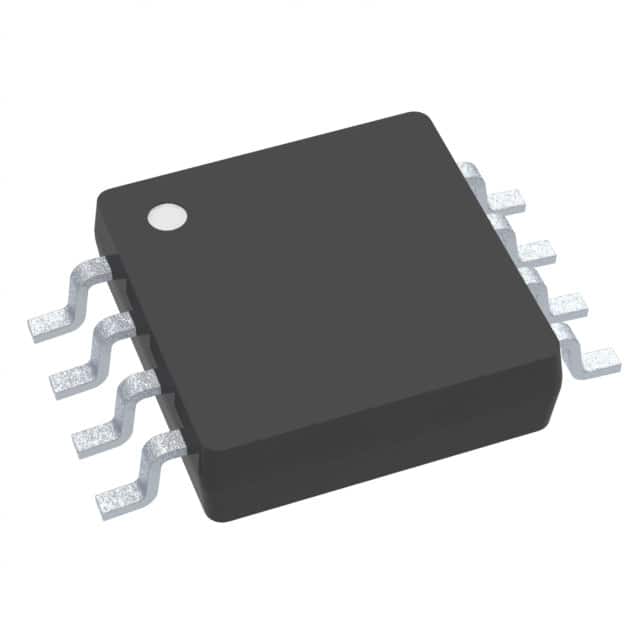
Analog Devices Inc./Maxim Integrated DS18B20U+
- Part No.:
- DS18B20U+
- Manufacturer:
- Analog Devices Inc./Maxim Integrated
- Category:
- Analog and Digital Output
- Package:
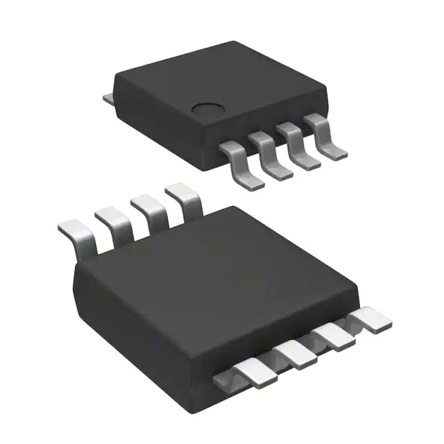
- 8-TSSOP, 8-MSOP (0.118", 3.00mm Width)
- Datasheet:
-
 DS18B20U+.pdf
- Description:
- SENSOR DIGITAL -55C-125C 8UMAX
- Quantity:
- Payment:

- Shipping:

Inventory:1,538
Please send an inquiry. Send us your inquiry, and we will respond immediately.
Product details
Overview
DS18B20U+ from Maxim Integrated (now Analog Devices) is a programmable-resolution 1-Wire digital thermometer with parasitic power capability, measuring -55°C to +125°C with ±0.5°C accuracy from -10°C to +85°C, and featuring nonvolatile alarm thresholds and unique 64-bit ROM addressing for multidrop bus operation in distributed temperature sensing systems.
For engineers reviewing the DS18B20U+ datasheet, DS18B20U+ pinout, DS18B20U+ application, or DS18B20U+ equivalent, key selection considerations include 1-Wire interface compatibility, parasitic vs. VDD-powered operation, 9–12-bit resolution tradeoffs, alarm search functionality, and µSOP-8 package mechanical constraints for high-density PCB layouts.
Technical Context
The DS18B20U+ implements a fully integrated 1-Wire interface using open-drain DQ signaling with weak pullup support and optional strong pullup control during temperature conversion or EEPROM write cycles. Its internal architecture includes a bandgap-based temperature sensor, 16-bit sign-extended two's complement output register, and scratchpad memory with EEPROM-backed TH/TL alarm registers and configuration byte.
It supports two power modes: local VDD supply (pin 3 connected to 3.0–5.5V) or parasite power (pin 3 grounded), where energy is harvested via DQ during bus high periods and stored on an internal capacitor (CPP). Alarm detection uses real-time comparison of converted temperature against user-programmed 8-bit TH/TL thresholds, with flag status accessible via Alarm Search [ECh] command.
Key Specifications
| Parameter | Value and Actual Design Meaning |
|---|---|
| Temperature Range | -55°C to +125°C operating range - enables use in industrial freezers, automotive under-hood, and HVAC ducts without external compensation. |
| Accuracy | ±0.5°C from -10°C to +85°C - meets Class B RTD-grade precision for thermostatic control and environmental monitoring. |
| Resolution | Programmable 9–12 bits (0.5°C to 0.0625°C steps) - allows runtime tradeoff between measurement granularity and 750ms max conversion time at 12-bit. |
| Interface | Single-pin 1-Wire® (DQ) with CRC-8 error checking - eliminates UART/I²C routing complexity and supports >100-node multidrop buses on one trace. |
| Power Modes | Parasite power (2-pin: DQ + GND) or VDD-supplied (3-pin: DQ + GND + VDD) - simplifies wiring in inaccessible locations like embedded concrete sensors or sealed enclosures. |
| Alarm Function | User-programmable nonvolatile TH/TL registers with Alarm Search command - enables centralized fault detection across dozens of sensors without polling each individually. |
| Unique ID | Factory-lasered 64-bit ROM code (family code 0x28) - guarantees unambiguous device identification in mixed-sensor 1-Wire networks. |
Pinout & Package
DS18B20U+ is housed in an 8-pin µSOP package (2.0mm × 2.5mm, 0.5mm pitch), optimized for space-constrained PCBs. Pin 1 = DQ (bidirectional 1-Wire data/power), Pin 4 = GND, Pin 8 = VDD (must be grounded for parasite power mode); pins 2,3,5,6,7 are no-connect.
| Pin/Terminal | Circuit Role | Design Meaning |
|---|---|---|
| 1 | DQ | Open-drain 1-Wire bidirectional I/O - carries data, clock, and parasitic power; requires external 4.7kΩ pullup resistor. |
| 4 | GND | Signal and power reference ground - must be low-impedance connection to avoid 1-Wire timing violations. |
| 8 | VDD | Optional local power supply input (3.0–5.5V) - grounded in parasite power mode; enables continuous operation during DQ bus low periods. |
| 2,3,5,6,7 | N.C. | No internal connection - left unconnected on PCB; no thermal or electrical function. |
Key Features
| Feature | Design Value |
|---|---|
| 1-Wire Interface | Single-data-line communication reduces MCU GPIO usage and eliminates protocol translation ICs in multi-sensor nodes. |
| Parasitic Power Mode | Operates with only DQ and GND connections - eliminates dedicated power traces and regulators in remote sensor deployments. |
| Nonvolatile Alarm Registers | TH/TL thresholds retain settings across power cycles - enables autonomous over-temperature shutdown without host intervention. |
| Multi-device Bus Support | Unique 64-bit ROM IDs allow >100 DS18B20U+ units on one 1-Wire bus - ideal for building-wide temperature mapping or server rack monitoring. |
| Configurable Conversion Time | 9–12-bit resolution selectable via scratchpad register - balances measurement speed (93.75ms) vs. precision (0.0625°C) per application need. |
Applications
| Industrial Process Monitoring | HVAC Environmental Control |
|---|---|
|
Use Scenario: Real-time temperature logging inside chemical reactor vessels and steam lines where wiring access is limited. IC Role / Device Role / Timing Role: Primary temperature sensor node communicating via 1-Wire to PLC-mounted master controller. Use Value: Parasite power eliminates need for isolated DC-DC converters in hazardous areas; ±0.5°C accuracy ensures process compliance with ASME B31.3 standards. |
Use Scenario: Zoned temperature feedback for commercial building VAV boxes and chilled water manifolds. IC Role / Device Role / Timing Role: Distributed ambient sensor feeding setpoint corrections to BACnet-enabled DDC controllers. Use Value: Multidrop 1-Wire bus reduces cabling cost by >60% versus analog 4–20mA transmitters; alarm search identifies failed zones without individual polling. |
| Consumer Appliance Sensing | Data Center Server Rack Monitoring |
|
Use Scenario: Thermal protection in smart ovens, refrigerators, and washing machine drum assemblies. IC Role / Device Role / Timing Role: Safety-critical temperature monitor interfacing directly with appliance MCU over short 1-Wire trace. Use Value: TO-92-compatible µSOP-8 footprint allows drop-in replacement in legacy designs; nonvolatile alarms trigger immediate shutdown before component damage. |
Use Scenario: Hot-spot detection on GPU/CPU heatsinks and power supply modules across 42U racks. IC Role / Device Role / Timing Role: High-density thermal node deployed at 5cm intervals along rail-mounted sensor strips. Use Value: 2.0mm × 2.5mm µSOP package enables 24+ sensors per meter; CRC-8 validation prevents false thermal throttling from EMI-induced bus errors. |
Equivalent & Alternatives
The following parts are listed as comparable options for similar digital thermometer applications.
| Alternative Part | Technical Difference | Application Difference | Selection Advice |
|---|---|---|---|
| DS18B20+T | Identical core specs but in TO-92 through-hole package; lacks µSOP-8 footprint compatibility. | Suitable for prototyping or low-volume assemblies where manual soldering is acceptable. | Select DS18B20+T only when board space permits TO-92 mounting and reflow compatibility is not required. |
| MAX31820M+ | Successor IC with same 1-Wire interface, improved ±0.25°C accuracy (−10°C to +85°C), and enhanced parasite power stability above +100°C. | Better suited for high-reliability applications requiring tighter tolerance or extended high-temp operation. | Choose MAX31820M+ when upgrading legacy DS18B20U+ designs for higher accuracy or >+100°C sustained operation. |
Compared with DS18B20+T, DS18B20U+ offers superior PCB density and automated assembly compatibility; compared with MAX31820M+, it provides cost-optimized performance for standard industrial temperature ranges without requiring firmware changes.
Availability
DS18B20U+ is available at Aetrix Electronics and suitable for HVAC environmental controls, industrial process monitoring, and consumer appliance thermal protection requiring stable component supply across long production lifecycles.
Supply support for DS18B20U+ includes scheduled delivery planning, volume procurement assistance, BOM continuity management, traceable sourcing, and lifecycle availability coordination for OEM customers, industrial embedded developers, connected-device designers, and electronics production programs.
Manufacturer
Analog Devices acquired Maxim Integrated in 2021 and maintains full technical and supply chain continuity for legacy Maxim sensor products including the DS18B20 series.
The DS18B20U+ belongs to Maxim's 1-Wire sensor family, designed specifically for low-cost, wire-efficient distributed temperature measurement in resource-constrained embedded systems.
FAQ
What is the difference between DS18B20U+ and DS18B20+?
The DS18B20U+ is the µSOP-8 packaged variant of the DS18B20 digital thermometer, while DS18B20+ typically refers to the SO-8 or TO-92 versions. All share identical electrical specifications, 1-Wire protocol, and temperature performance, but DS18B20U+ uses a smaller 2.0mm × 2.5mm footprint optimized for high-density PCBs. The DS18B20U+ part number specifically denotes the µSOP package with lead-free, RoHS-compliant finish.
Can DS18B20U+ operate without an external power supply?
Yes, DS18B20U+ supports parasite power mode, drawing energy from the 1-Wire bus via the DQ pin during high periods and storing charge on an internal capacitor. In this mode, VDD (pin 8) must be grounded, and a strong pullup (e.g., MOSFET-switched 3.3V/5V rail) is required during temperature conversions to supply up to 1.5mA peak current. This eliminates the need for separate VDD traces in remote sensor nodes.
How does the DS18B20U+ alarm function work in practice?
The DS18B20U+ stores user-defined upper (TH) and lower (TL) temperature thresholds in nonvolatile EEPROM. After each conversion, it compares the result and sets an internal alarm flag if outside bounds. The host MCU can then issue an Alarm Search [ECh] command to identify all DS18B20U+ devices on the bus with active alarms-enabling rapid fault isolation in large-scale deployments without individual address polling.
What is the maximum number of DS18B20U+ sensors on a single 1-Wire bus?
There is no hard limit on DS18B20U+ count per 1-Wire bus due to its unique 64-bit ROM addressing. Practical limits depend on bus capacitance, pullup strength, and cable length: up to 50–100 units are reliably supported with proper 4.7kΩ pullup and twisted-pair cabling. Each DS18B20U+ responds only to commands containing its specific ROM code, preventing address conflicts in multidrop configurations.
Does DS18B20U+ require external components for basic operation?
No external components are required for DS18B20U+ basic operation beyond a 4.7kΩ pullup resistor on the DQ line. Unlike analog sensors, it integrates the temperature transducer, ADC, EEPROM, and 1-Wire interface into a single die. No calibration resistors, op-amps, or voltage references are needed-reducing BOM count and layout complexity while maintaining ±0.5°C accuracy across its primary operating range.
DS18B20U+ Specifications
- Product attributes
- Attribute value
- Manufacturer:
- Analog Devices Inc./Maxim Integrated
- Series:
- -
- Package/Case:
- 8-TSSOP, 8-MSOP (0.118", 3.00mm Width)
- Packaging:
- Tube
- Product Status:
- Active
- Sensor Type:
- Digital, Local
- Sensing Temperature - Local:
- -55°C ~ 125°C
- Sensing Temperature - Remote:
- -
- Output Type:
- 1-Wire®
- Voltage - Supply:
- 3V ~ 5.5V
- Resolution:
- 12 b
- Features:
- Output Switch, Programmable Limit, Programmable Resolution
- Accuracy - Highest (Lowest):
- ±0.5°C (±2°C)
- Test Condition:
- -10°C ~ 85°C (-55°C ~ 125°C)
- Operating Temperature:
- -55°C ~ 125°C
- Mounting Type:
- Surface Mount
- Grade:
- -
- Qualification:
- -
- Supplier Device Package:
- 8-uMAX/uSOP
DS18B20U+ FAQ
1.How can I place an order for DS18B20U+ through Aetrix?
Please submit a Request for Quotation (RFQ) for DS18B20U+ on Aetrix. Our sales agent will provide a competitive quotation and guide you through the order confirmation once you accept the terms.
2.Are the price and stock information for DS18B20U+ reliable?
The price and inventory of DS18B20U+ are updated periodically and may fluctuate due to market conditions. Stock and pricing data are typically refreshed every 24 hours. Quotation validity for DS18B20U+ is usually 5 days.
3.What payment methods are accepted for DS18B20U+?
We accept Wire Transfer, PayPal, Credit Card, Western Union, MoneyGram, and Escrow for DS18B20U+ transactions.
Note: Certain payment methods may incur a processing fee.
4.How is shipping managed for DS18B20U+?
DS18B20U+ orders can be shipped via leading logistics carriers, including DHL, UPS, FedEx, TNT, or Registered Mail.
Once your DS18B20U+ order is processed, you will receive an email with the shipment details and tracking number.
Note: Tracking information may take up to 24 hours to appear. Express delivery typically takes 3–5 business days.
5.How can I obtain technical support or documentation for DS18B20U+?
For technical support, including DS18B20U+ datasheets, pinout diagrams, or application guidance, please contact our engineering support team. They can provide detailed documentation and assistance for your DS18B20U+ requirements.
6.How does Aetrix verify that DS18B20U+ is sourced from the original manufacturer or authorized distributors?
All DS18B20U+ products on Aetrix are procured from qualified distributors and authorized channels. Our dedicated quality assurance team conducts strict verification, including traceability checks and, if necessary, third-party testing. This ensures that DS18B20U+ meets industry standards.
7.What is the process for return or replacement of DS18B20U+?
All DS18B20U+ units undergo pre-shipment inspection (PSI). If there is an issue with DS18B20U+, returns or replacements are accepted under the following conditions:
1.Quantity discrepancies, incorrect items, or visible external defects (such as breakage or corrosion), acknowledged by Aetrix.
2.The issue is reported within 90 days of delivery.
3.The DS18B20U+ part is unused and in its original packaging.
Return procedure for DS18B20U+:
1.Submit a request within 90 days.
2.Obtain a Return Material Authorization (RMA) from Aetrix.
DS18B20U+ Tags
-
MCP9700T-E/TT
Microchip Technology
-
MCP9700T-E/LT
Microchip Technology
-
MCP9701T-E/TT
Microchip Technology
-
MCP9701T-E/LT
Microchip Technology

-
TMP235A4DBZR
Texas Instruments
-
MCP9700AT-E/TT
Microchip Technology
-
MCP9700AT-E/LT
Microchip Technology
-
MCP9701AT-E/LT
Microchip Technology
-
MCP9701AT-E/TT
Microchip Technology
,TO-226_straightlead.jpg)
-
LM335Z
STMicroelectronics
-
TMP1075NDRLR
Texas Instruments
-
TMP1075DGKR
Texas Instruments
Tech Hub

A practical engineering guide to 3.3V and 5V logic compatibility, input thresholds, resistor dividers, translator ICs, MOSFET level shifting, I2C pull-ups, timing limits and power-sequencing risks.

The 74HC595 uses push-pull logic outputs, while the TPIC6B595 uses 50 V open-drain DMOS sinks for higher-power loads. This guide compares timing, current limits, 3.3 V interfacing, load wiring, thermal…

The 74HC595 converts serial data into eight stable parallel outputs. This guide covers pin functions, shift and storage timing, OE and MR behavior, drive-current limits, cascading, voltage compatibilit…

A technical comparison of level-sensitive latches and edge-triggered flip-flops, covering timing windows, setup and hold limits, master–slave operation, time borrowing, race-through, HDL inference and…

A D latch stores one bit while Enable controls when data can pass. This reference covers gate-level operation, truth tables, transparency, setup and hold timing, LE versus OE, common ICs and practical …

An SR latch stores one bit through cross-coupled feedback. This engineering reference covers NOR and NAND implementations, truth tables, forbidden-state recovery, gated operation, switch debouncing, fa…

Latch circuits retain one bit through feedback. This technical reference covers SR and D latches, truth tables, transparency, timing limits, latch-versus-flip-flop behavior, applications and common log…

An engineering guide to LED driver operation, constant-current and constant-voltage outputs, linear and switching topologies, dimming, IC selection, calculations, replacement compatibility, and fault c…

Operational amplifier guide covering op amp basics, feedback, ideal vs real op amps, common configurations, buffer circuits, offset, bias current, gain-bandwidth, slew rate, rail-to-rail limits and sel…

Jumper cables guide covering safe connection order, red and black clamp placement, final ground connection, cable gauge, length, clamp quality, copper vs CCA cables, jump starter comparison and battery…


